16. Interface and application programming
Processing
I watched this video from Processing was on the main page of Processing and directed me (a user who had no experience in Processing at all) to the Hello Processing Tutorial. The Hello Processing page, I believe, is intended to be used during the Hour of Code week.
Kai’s summary of what he learned about Processing
- Processing = visual, user friendly, intended for those who are unfamiliar with programming/coding (ie. artists)
- Java/Python: Many adaptations of this environment
- Hit play to run the code: Window pops up where visual things show up
- Some codes don’t have visual window things
- Window popping up means that the code is running
- Java: running the function and then defining the function later
- Parametric: ie. defining window size of the window that pops up in pixels
Hour of Code Tutorial
Here’s the link to the tutorial that I went through again. It was really basic since Hour of Code is meant for kids, but it gave me a good understanding on the basics of Processing and how to set up the page and similar setup things.
I learned that, in general, the order in which you write code matters. For example, if you code two shapes, that overlap in the canvas, the shape that was coded second will appear to be on top of the other shape. Like Arduino, Processing has a setup loop that is established by using void setup (){ code }. Instead of having void loop like Arduino, Processing has void draw () { code }. It is standard to establish the canvas’s background color in void setup by coding background (R,G,B);. To set the canvas size (in pixels), you would use size(width, height);.
To draw shapes, you use shape (X location, Y location, width, height);. To change stroke and fill color, you put the following code before the shape that these colors will apply to.
stroke( R,G,B);
 fill (R,G,B);
For the X and Y location of shapes, you can set it so that the X and Y location is a variable. In the tutorial, they used the variable mouseX and mouseY. These are variables that are understood by Processing without defining the variable myself and are just the X and Y coordinates of the cursor of the computer. I later found these variables on the Processing reference page. Here’s some code that enables you to move a square around the canvas with your mouse:
Code 1
void setup () {
  size (500,500);
}

void draw (){
background (0,0,0);
rect (mouseX,mouseY,50,50);
}
What the code does:
Notice that the background definition code is in the loop and not void setup.
Code 2
void setup () {
  size (500,500);
  background (0,0,0);
}

void draw (){

rect (mouseX,mouseY,50,50);
}
The only difference between Code 1 and Code 2 is that the background function is in void setup.
What the code does:
Code 2 left a “trail” behind because it was not continually refreshing the background as Code 1 was. So, you see all of the previous locations of the rectangle in addition to the current location.
Processing with Stepper Motor
For this week, I have to
write an application that interfaces a user with an input &/or output device that I made.
Since I had no idea how to interface my output device, a stepper motor, I just searched the Processing site for “stepper motor.” I found a forum thread where a user wanted to use Processing to control DC motors and stepper motors and was directed to the Serial Library section of Processing.
Research
As I was looking around, I visited a bunch of different sites and learned a bunch of random things about processing as I went. I’ve documented what I learned here.
I kept on seeing import processing.serial.*; at the top of people’s code in Processing. I went to the Processing reference page and found out that this is Processing’s way of calling upon a library. It is the same thing as Arduino’s #include statements.
Mark on this Arduino forum was able to get his bipolar stepper motor to be controlled by Processing. Another person on the forum explained serial communication with a mail analogy.
[This Purdue PDF] discussed how to use Processing and various types of motors. It has a lot of good information and even explains the code it gives, but it does not mention how to control stepper motors.
I also referenced this page and this page for research.
This Instructables tutorial proved the most helpful with regard to code (I think). The post talks about how to make some sort of machine. Its axes are controlled with stepper motors and Firmata in Processing. I saw in the beginning that it uses two libraries, including the Arudino Firmata library. I didn’t think that the Arduino Firmata library could work with an ATtiny44, so I didn’t pursue it further.
Final idea
I wanted to use Processing to send a character that I type on my keyboard to the serial monitor and have the stepper motor respond accordingly, like by turning on/off or speeding up/slowing down when certain characters are sent.
Code on Arduino
First, I changed my Arduino code so that the stepper would turn on if a character was sent. To do this, I had to understand the existing code that I had from week 12 better.
I saw that there was a switch / case statement, so I learned about it in this huge Arduino reference PDF. On page 26, it discusses switch / case statements. This little piece of example code explained what it does pretty well:
switch (var) {
 case 1:
 //do something when var == 1
 break;
 // break is optional
 case 2:
 //do something when var == 2
 break;
 default:
 // if nothing else matches, do the default
 // default is optional
 }
The var is the variable that I am using with the case statements. As the var changes, what the program does is different. If none of the conditions described are met (like the variable is something other than what is offered in previous statements), then the default will occur. The break tells the switch statement to stop checking through the other variables for any other matches and to exit the statement. Without the break, if it matches two variables, then it will run both (which you may or may not want it to do). The break is optional.
I have to insert an if statement into my code, like “if this character is received, start the stepper.”
I got a simpler piece of code that uses the stepper library that is automatically in Arduino.
#include <Stepper.h>

#define STEPS 2038 // the number of steps in one revolution of your motor (28BYJ-48)

Stepper stepper(STEPS, 2,3,4,5);

void setup() {
// nothing to do
}

void loop() {
stepper.setSpeed(1); // 1 rpm
stepper.step(2038); // do 2038 steps -- corresponds to one revolution in one minute
delay(1000); // wait for one second
stepper.setSpeed(6); // 6 rpm
stepper.step(-2038); // do 2038 steps in the other direction with faster speed -- corresponds to one revolution in 10 seconds
}
I altered it so that it moves faster, changing stepper.setSpeed(1); // 1 rpm into stepper.setSpeed(10); // 10 rpm. I also got rid of the part where it goes the other way and the delay. I don’t need it to turn the other way.
I played around with this code to get it to receive something from the serial monitor and start up when it receives a character from Processing.
#include <Stepper.h>
#include <SoftwareSerial.h>         // ATtinys cannot use Arduino's serial, only Software Serial

#define STEPS 2038                  // the number of steps in one revolution of your motor (28BYJ-48)
int inByte = 0;

Stepper stepper(STEPS, 2,3,4,5);    //pins that are attached to the stepper
SoftwareSerial myserial(9,10);      // RX and TX pins, respectively


void setup() {
myserial.begin(9600);               // establishes baud rate at 9600
}

void loop() {
 while (myserial.available() > 0) { //receive data
    inByte = myserial.read();       //read the incoming byte
 }
 if (inByte == 1)                   // if it receives "1" from Processing, it starts the stepper motor
 {
  stepper.setSpeed(10);             // 10 rpm
  stepper.step(2038);               // do 2038 steps -- corresponds to one revolution in one minute
  }

 }
Originally, I tried to use normal Serial functions that Arduino uses, but ATtinys cannot use Arduino’s serial. I’ve circumvented this in several Fab weeks (including Week 11, inputs) now by using the Software Serial library.
I referenced the first two lines in void loop from an Arduino Reference page that talks about communication with the serial monitor.
Don’t download this version of my Arduino code, it doesn’t work.
Code on Processing
Mr. Rudolph helped me out by giving me a Code in Processing that would send certain characters to the Serial Monitor when a certain key was pressed. His original version sent letter characters to the Serial Monitor, but I changed it just so that “a” would send over a 1. I planned on editing it later on so that I could press certain buttons within the Processing popup window that would turn on the stepper, turn off the stepper, and change the speeed of the stepper.
Here’s the altered code:
import processing.serial.*;

Serial myPort;  // Create object from Serial class
int val;        // Data received from the serial port

void setup()
{
  size(500, 500);
 String portName = "COM19";
 myPort = new Serial(this, "COM19", 4800);
}

void draw() {
  // keep draw() here to continue looping while waiting for keys
}

void keyPressed() {
  if (key == 'w') {
    myPort.write('w');
  }
  else if (key == 'a') {
    myPort.write('1');
    rect (250,250,50,50);
  }
  else if (key == 'd') {
    myPort.write('d');
  }
  else if (key == 's') {
    myPort.write('s');
  }
  else{
    myPort.write('x');
  }
}
Though there is code indicating what to do when w, d, s, and x is typed on the keyboard, I mainly ignored those and just paid attention to the “a” because I wanted to get one basic thing working before I added more layers. We love spiral development.
In adition to the fact that a typed “a” yields a “1” in the Serial Monitor, I also added a rectangle that would pop up when “a” is typed, just so that I know that Processing is receiving the input that I gave it (the typed “a). This function proved super helpful later on in the process. I was typing “a” but the rectangle wasn’t showing up, and I couldn’t figure out why. I quickly discovered it was because my keyboard was on caps lock and that I was actually typing “A” in upper case. I avoided quite a bit of confusion by adding in this helpful function.
Download my basic Processing files (V1)
Processing and Arduino
When I hit “a” on Processing, the rectangle showed up, but nothing happened with the stepper. The TX light on the FTDI lit up, but the stepper didn’t do anything.
I tried to change and use the AltSoftSerial Library for Arduino (which is apparently more efficient). I discovered this library after reading this Arduino forum about connecting Arduino and Processing. According to this website, it is much more efficient than the Software Serial library and enables the user to simultaneously receive and transmit data, whereas the Software Serial library only allows you to do one at a time. However, after using it very briefly, I saw that it only works with very specific pins on certain boards (like pins 8 and 9 on an Arduino Uno) since it has to have the right 16 bit timer hardware. Since the ATtinys do not have the correct hardware, I could not use this library.
I genuinely didn’t understand why it wasn’t working. The TX light lit up, meaning that my board received something from my computer, but still nothing happened. It was probably the fact that whatever it was receiving wasn’t in the right format.
Dr. Harris’s help
Dr. Harris helped me out at this point. We found that boards with 20mHz crystal resonators were able to communicate back to the computer, whereas boards without the resonators were not able to. This is why we had the resonators on our Week 7 Echo Hello World boards (the boards communicated back to the Serial Monitor). So, I had to make another board that was basically the same as my Week 12 outputs board but had a crystal resonator.
Here’s my modified schematic:

I added one resistor as a jump resistor. I had one air wire that I had to fix once I got to making the board.
Here’s my modified board:

To make sure that this board was properly communicating with my laptop before adding in the Processing component, I used an edited version of the Software Serial library example:
Here’s the code I used to test my board:
#include <SoftwareSerial.h>

SoftwareSerial mySerial(0, 1); // RX, TX

void setup() {
  // set the data rate for the SoftwareSerial port
  mySerial.begin(4800);
  mySerial.println("Hello, world?");
}

void loop() { // run over and over
  if (mySerial.available()) {
    Serial.write(mySerial.read());
    mySerial.write(Serial.read());
  }
}
This sent characters back to the Serial Monitor when the user sent characters (also through the Serial Monitor). When I did this with my new board, it was supposed to echo back what I had originally given it. It didn’t send back exactly what I gave it originally, but it was sending something back. This meant that the board was actually able to make and send a transmission. Once it was doing that, I moved on and added Processing.
Download my Arduino test files
My Processing code was, very clearly, working properly. I It was really just the Arduino code that I had to go back and fix.
What eventually worked was that I took the example software serial code and put the necessary stepper code into it. When I wrote the code the first time, I put the software serial code into the stepper motor code. When I compare the two codes side by side, there isn’t really much different between the two. It’s quite frustrating that my code was so close yet still didn’t work.
Here’s the code that worked:
#include <Stepper.h>
#include <SoftwareSerial.h>         // ATtinys cannot use Arduino's serial, only Software Serial

#define STEPS 2038                  // the number of steps in one revolution of your motor (28BYJ-48)
byte inByte =0;

Stepper stepper(STEPS, 2, 3, 4, 5);    //pins that are attached to the stepper
SoftwareSerial myserial(2, 1);      // RX and TX pins, respectively


void setup() {
myserial.begin(4800);             // establishes baud rate at 4800
}
void loop() {
 if (myserial.available() > 0)      //if received data is greater than one byte, get it from the buffer and
 {
    inByte = myserial.read();       //read the incoming byte
    myserial.println(inByte);

    if (inByte != 0)                   // if it receives anything other than "0" from Processing, it starts the stepper motor
    {
        stepper.setSpeed(10);             // 10 rpm
        stepper.step(2038);               // do 2038 steps -- corresponds to one revolution in one minute
        myserial.println(inByte);
     }
  }
 }
Download my working Arduino files
Here’s my working stepper after sending the message from Processing:
Group Project
MIT App Inventor (Kai)
- Modular
- Scratch but for apps
- You can test your apps on Android devices
Chili Peppr (Kai)
Chili Peppr is a “Javascript software workspaces that talk to your hardware”. We plan to use it in conjunction with the GRBL workspace for our gCode.
Processing (Kai)
Processing is a visual, user friendly interface tool. Arduino IDE is built on Processing. It works with Java or Python; there are additional adaptations of the architecture linked below.
Different Adaptations of the Program: - Processing Javascript - Processing Python - Processing Android - Processing Pi
- Hit play to run the code, visually similar to serial monitor to python
- Might not have visuals - screen running indicates that program is running
- Define window size (in pixel size) - use variables to make program parametric
Wiring (Will)
-open source programming framework for microcontrollers -used to create all kinds of creative coding, interactive objects, spaces or physical experiences -includes support for many different hardware architectures -used for learning, prototyping, and finished professional work production
The site is well documented with many helpful resources that can be found here
-Wiring builds off of Processing which Kai documented above.
Simulink (Will)
Simulink, built around simulation and model based design. It is an evolution and add on of Matlab
- Allows you to analyze and understand complex systems by giving you block based diagrams
- start model simulation by simply pressing the play button
- allows you to simulate and analyze a broad range of signals from digital to analogue to mixed
- allows you to compare the progress of your algorithms to that of your targeted goal
- has additional capabilities for model based design
- you can generate code from a model to prototype and test things in real time
Arduino Firmata (Katie)
Firmata is an Arduino library that utilizes the Firmata Protocol to software communication.
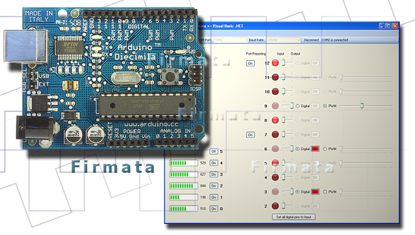
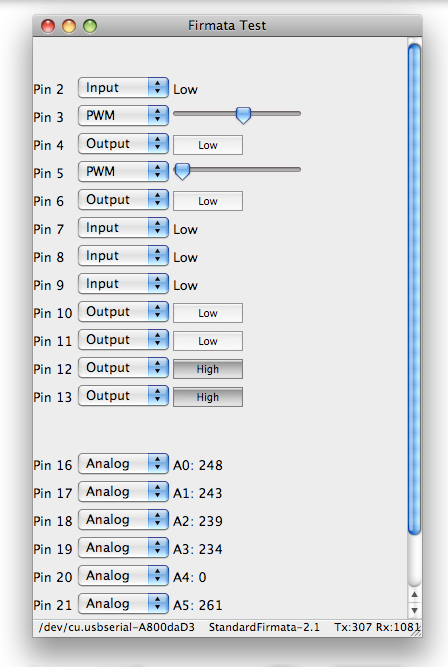
*These photos were found from this source
Here is some example code listed on the Firmata Arduino page.
This code starts the Firmata library.
begin(); //start the library
begin(long); //start the library and override the default baud rate
begin(Stream &s); // start the library using a [Stream](http://www.arduino.cc/en/Reference/Stream) other than Serial (eg Serial1 or EthernetClient)
printVersion(); //send the protocol version to the host computer
blinkVersion(): //blink the protocol version on the build in LED (typically pin 13)
printFirmwareVersion(); //send the firmware name and version to the host computer
setFirmwareVersion(byte major, byte minor); //set the firmware name and version, using the sketch's filename, minus the '.ino'
setFirmwareNameAndVersion(const char *name, byte major, byte minor); //set both the name and version of the firmware
This code sends messages.
sendAnalog(byte pin, int value); //send an analog message
sendDigitalPort(byte portNumber, int portData); //send an 8-bit port in a single digital message
sendString(const char* string); //send a string to the host computer
sendString(byte command, byte bytec, byte *bytev); //send a string to the host computer using a custom command type
sendSysex(byte command, byte bytec, byte* bytev); //send a command with an arbitrary array of bytes
write(byte c); //write a byte to the Stream
This code receives the messages.
available(); //check to see if there are any incoming messages in the buffer
processInput(); //process incoming messages from the buffer, sending the data to any registered callback functions
attach(byte command, callbackFunction myFunction); //attach a function to an incoming message type
detach(byte command); //detach a function from an incoming message type
This examples is for sending and receiving messages.
#include <Firmata.h>

byte analogPin;

void analogWriteCallback(byte pin, int value)
{
  pinMode(pin, OUTPUT);
  analogWrite(pin, value);
}

void setup()
{
  Firmata.setFirmwareVersion(FIRMATA_MAJOR_VERSION, FIRMATA_MINOR_VERSION);
  Firmata.attach(ANALOG_MESSAGE, analogWriteCallback);
  Firmata.begin();
}

void loop()
{
  while (Firmata.available()) {
    Firmata.processInput();
  }
  for (analogPin = 0; analogPin < TOTAL_ANALOG_PINS; analogPin++) {
    Firmata.sendAnalog(analogPin, analogRead(analogPin));
  }
}
Firmata Protocol
The Firmata Protocol is a protocol that aids in software communication with microcontrollers to computers. The Firmata Protocol can be used on any microcontroller and any computer!
Firmata Protocol is “based on the midi message format in that commands bytes are 8 bits and data bytes are 7 bits” (soundanalogous). Ex. “MIDI Channel Pressure (Command: 0xD0) message is 2 bytes long, in Firmata the Command 0xD0 is used to enable reporting for a digital port (collection of 8 pins)” (soundanalogous). “In Firmata, the number of bytes in a message must conform with the corresponding midi message” (soundanalogous).
MIDI Messages Format
This link provides a table for MIDI Messages. It is in binary order!
Python / mbed SDK / RPC (Katie)
To understand interfacing with Python, I looked at this [tutorial] (https://os.mbed.com/cookbook/Interfacing-with-Python).
The tutorial referenced this developmental kit. It is called the mbed SDK. It is a C/C++ platform, but I read the tutorial for interfacing with Python.
Here are the different platforms that can be used to interface with Python.
Windows:
-
Run Python Windows Binary
-
Run Python Win32 Extensions
-
Run Python Serial Port Extension
Mac:
-
Python already installed
-
Run terminal ( sudo easy_install pyserial)
Linux: - Python is probably already installed
- Terminal (sudo easy_install pyserial)
RPC
mbed libraries (this is the company that the tutorial came from) support RPC so you can interface using that. I referred to this tutorialto learn about RPC interfacing.
HTTP
This is an HTTP example of Hello World code which references the Python RPC library.
1 2 3 4 5 6 7 8 9 10 11 | python >>> from mbedrpc import * >>> mbed = HTTPRPC("192.168.0.4") >>> x = DigitalOut(mbed,"LED1")#These objects should already exist on mbed >>> z = DigitalOut(mbed,"LED2") >>> ain = AnalogIn(mbed, "LED3") >>> x.write(1) >>> z.write(0.5) >>> ain.read() 0.786757474 >>> |
I decided to focus on RPC with serial.
Serial
Here is how to connect to the COM port.
1 2 3 4 5 6 | python >>> import serial >>> serdev = 15 >>> s = serial.Serial(serdev) >>> s.write("hello") >>> s.close( |
This is a Serial example of RPC that receives the commands from the serial port and then pass them.
#include "mbed.h"
#include "mbed_rpc.h"

/**
 *  This example program has been updated to use the RPC implementation in the new mbed libraries.
 *  This example demonstrates using RPC over serial
 */

//Use the RPC enabled wrapped class  - see RpcClasses.h for more info
RpcDigitalOut myled(LED4,"myled");

Serial pc(USBTX, USBRX);
int main() {
    //The mbed RPC classes are now wrapped to create an RPC enabled version - see RpcClasses.h so don't add to base class

    // receive commands, and send back the responses
    char buf[256], outbuf[256];
    while(1) {
        pc.gets(buf, 256);
        //Call the static call method on the RPC class
        RPC::call(buf, outbuf);
        pc.printf("%s\n", outbuf);
    }
}
Processing Python (Me)
- Processing Python = interaction of Processing
- Visual emphasis, like Processing in Java
- Write Processing code in Python
Firefly (Me)
- Code to nodes and back
- Grasshopper’s visual programming interface - can manipulate elements graphically and quickly prototype
- Has an advanced code generation feature that translates the visual program into Arduino code
- Has many prebuilt components that enable the user to connect to popular hardware devices (like an Xbox)