Final Project
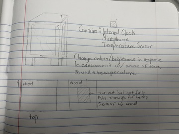
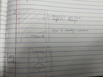
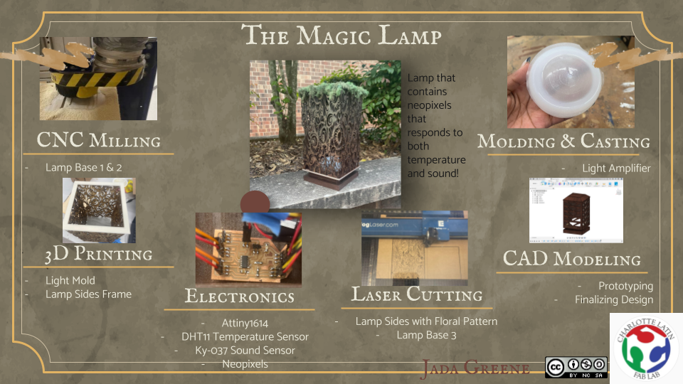
I am making an interactive mood lamp. This lamp will contain an:
-
Microphone
-
Temperature Sensor
This lamp will change colors/brightness in response to environments with a sense Of temperature, and sound. I decided on this project because freshman year I did a big LED sign that changed color based on the temperature it was in the room. I wanted to take the idea of that project and take it to another level by adding more Sensors and making it into a design that is more aesthetically pleasing. I also have a not weird long love for lights and lamp fixtures. I love all my projects lighting up or Glowing in some way or another.
Pre-Project Design Specification Considerations
- What do you want your project to do?
I want my lamp to be able to react to voices and other sounds, change colors based on the temperature from body heat, and to have a sunrise progression mode [it will go from one color to another over the span of 30 minutes to wake me up at a certain time].
- Will your project be inside or outside?
It is going to be strictly indoors. I plan to create it out of wood which is easily worn and warped through outside elements.
- Will your project be portable?
It is a lamp so it will usually be stationary but yes, it is possible to move around.
- Will your project connect to the Internet?
No, it will not connect to the internet.
- Will your project use Bluetooth?
No, it will not use Bluetooth.
- Does your project use a vinyl cutter?
No, it is not a requirement for the project but if time permits, it would be a nice additive.
- Does your project use a laser cutter?
Yes, I will use it to create designs on the wood and cut out the thinner parts of the wood.
- Does your project use a 3D printer?
Yes my project uses a 3D project to create the mold for the half sphere inside the lamp.
- Does your project use a large CNC machine (Shopbot)?
I most likely will use the CNC to design the individual parts of the lamp such as the base or the top.
- Does your project have intelligence (Arduino, Raspberry Pi, computer)?
Yes, my project will use an arduino.
- What are your project inputs?
The inputs will be sound, and temperature.
- What are your project outputs?
My output is the lamp changing colors based on the inputs and the mode it is in.
- What are the dimensions of your project?
I am anticipating it to be no bigger than about 6x6x11 but that is subject to change.
- What materials will you use?
I plan on using wood, acrylic, and plastic from 3d printing.
- How will you conceal the electronics?
I want to have compartments built into the base and top of the lamp so I am able to hide the electronics and they can not be seen through the lamp but also still access them if needed.
##### More info on this check week 1
2D and 3D Modeling
More Info on this check week 3
Week Planning
| Date | Week | Project |
|---|---|---|
| Feb 02 | Computer-aided Design | No |
| Feb 09 | Computer-Controlled Cutting | No |
| Feb 16 | Electronics Production | No |
| Feb 23 | 3D Scanning and Printing | No |
| Mar 02 | Electronics Design | No |
| Mar 09 | Computer-Controlled Machining | No |
| Mar 16 | Embedded Programming | No |
| Mar 23 | Molding and Casting | Yes |
| Mar 30 | Output Devices | Yes |
| Apr 06 | Mechanical/Machine Design | No |
| Apr 13 | Break | — |
| Apr 20 | Input Devices | Yes |
| Apr 27 | Networking and Communications | No |
| May 04 | Interface and Application Programming | No |
| May 11 | Wildcard Week | — |
| May 18 | Applications and Implications | Yes |
| May 25 | Invention/Intellectual Property and Income | Yes |
| Jun 01 | Project Development | Yes |
| Jun 06 | Project Presentations | — |
Some of the earlier weeks I learned skills I am going to use for my final project but with the time I had I did not have the chance to make exactly what I needed for it yet.
Week 11 - Output Devices
Neopixels
This is the week I used for my final project. My output device is going to the RGB LED Neopixel lights. Then during inputs week I will add the switch and the sensors. I will focus on temperature for that week because that I believe will the most challenging.
More info on this check week 11
Week 13 - Input Week
Temperature Sensor
For input week on week 13 I explored the DHT11. I explored it further for my final project. I continued with the DHT11 and connected it to my neopixel strip like I did for output week but I changed the code. I used this code instead:
#include <FastLED.h>
#include <DHT.h>

#define DHTPIN 8 // Data pin for DHT
#define LEDPIN 9 //Data Pin for LEDs
#define NUM_LEDS 3 //Number of LEDs
#define DHTTYPE DHT11
uint8_t brightness = 255;
uint8_t hue = 0;
DHT dht(DHTPIN, DHTTYPE);
CRGB lds[NUM_LEDS];

void setup() {
  Serial.begin(9600);
  Serial.println("DHTxx test!");
  dht.begin();
  FastLED.addLeds<WS2812B, LEDPIN, GRB>(lds, NUM_LEDS);
}

void loop() {

  // Wait between measurements.
  delay(250);
  // Reading temperature or humidity takes about 250 milliseconds!
  // Read temperature as Celsius (the default)
  uint8_t t = dht.readTemperature();

  if (t >= 30) {
    hue = 0;
  }
  if (t < 30 && t >= 29) {
    hue = 50;
  }
  if (t >= 27 && t < 29) {
    hue = 85;
  }
  if (t < 27 && t >= 26) {
    hue = 120;
  }
  if (t < 26) {
    hue = 160;
  }

  for (uint8_t i = 0; i < NUM_LEDS; i++) {
    lds[i] = CHSV(hue, 255, brightness);
  }
  FastLED.show();

  // Check if any reads failed and exit early (to try again).
  if (isnan(t) ) {
    Serial.println("Failed to read from DHT sensor!");
    return;
  }

  Serial.print("Temperature: ");
  Serial.print(t);
  Serial.print(" *C ");
  Serial.print("Hue: ");
  Serial.print(hue);
  Serial.println();

}
This code shows on the serial monitor what the temperature (in Celsius) and what the hue of the light is. I was having trouble with the code at first because I only included > and < but I didn’t have =< and >=. The difference is the first means greater than & less than while the latter means greater than or equal to and less than and equal to. This was a big change because the Neopixel LES’s had no idea what to do if it was directly on the unspecified number.
Microphone
I had a lot of trouble with this one. I did it simultaneously with other weeks. I first started to use a 3 pin mic sensor and it was not working but I was told by a teacher, Adam Durrett, that I needed to use an analog mic. So I found a mic with 4 pins labeled, AO, G, +, and DO. I connected the AO pin to A1 on the arduino. The A stands for analog. Then I connected the ground and power to the arduino. I found this video that really helped me with this process. I then used this code from this site:
#include <FastLED.h>

int r=152;
int g=0;
int b=10;

#define LED_PIN     5            //CONNECT DATA PIN OF PIXEL WITH 5 NUMBER PIN OF ARDUINO
#define NUM_LEDS    16           //CHANGE THE VALUE IF YOU WANT TO USE DIFFRENT NUMBER OF LED IN YOUR STRIP,HERE IN MY STRIP NUMBER OF LED IS 60 SO I SET IT 60.

CRGB leds[NUM_LEDS];
CRGB led[NUM_LEDS];

int s=0;

void setup() {

  FastLED.addLeds<WS2812, LED_PIN, GRB>(leds, NUM_LEDS);
  for (int i = NUM_LEDS/2; i >= 0; i--)
  {
     leds[i] = CRGB ( r,g,b);
     leds[NUM_LEDS-i] = CRGB (r,g,b );
     delay(40);
    FastLED.show();
  }
  Serial.begin(9600);
   pinMode(A1,INPUT_PULLUP);

}
void loop()
{
  s=analogRead(A1);
  s=s*2;
  Serial.println(s);
 // delay(50);
  if((s>=450)&&(s<=550))
  {
    leds[(NUM_LEDS/2)-1]=CRGB (0, 0, 255);
    leds[NUM_LEDS/2]=CRGB (0, 0, 255);
  }
  else if((s>=400)&&(s<=450))
  {
    leds[(NUM_LEDS/2)-1]=CRGB (153, 153, 0);
    leds[NUM_LEDS/2]=CRGB (153, 153, 0);
  }
  else if((s>=350)&&(s<=400))
   {
     leds[(NUM_LEDS/2)-1]=CRGB (255, 50, 255);
    leds[NUM_LEDS/2]=CRGB (255, 50, 255);
   }
   else if((s>=300)&&(s<=350))
  {
    leds[(NUM_LEDS/2)-1]=CRGB (10, 25, 217);
    leds[NUM_LEDS/2]=CRGB (10, 25, 217);
  }

    else if((s>=276)&&(s<=300))
   {
     leds[(NUM_LEDS/2)-1]=CRGB (50, 50, 150);
    leds[NUM_LEDS/2]=CRGB (50, 50, 150);
   }
   else if((s>=250)&&(s<=275))
   {
     leds[(NUM_LEDS/2)-1]=CRGB (230, 0, 10);
    leds[NUM_LEDS/2]=CRGB (230, 0, 10);
   }
  else if((s>=235)&&(s<=250))
   {
     leds[(NUM_LEDS/2)-1]=CRGB (0, 160, 0);
    leds[NUM_LEDS/2]=CRGB (0, 160, 0);
   }
   else if((s>=200)&&(s<=230))
   {
     leds[(NUM_LEDS/2)-1]=CRGB (1, 0, 1);
    leds[NUM_LEDS/2]=CRGB (1, 0, 1);
   }
  else
  {
     leds[(NUM_LEDS/2)-1] = CRGB ( r,s-100,b);
     leds[NUM_LEDS/2] = CRGB ( r,s-100,b);
  }
    for (int i = 0; i <= ((NUM_LEDS/2)-2); i++)
  {
     leds[i] = leds[i+1];
     leds[NUM_LEDS-1-i] = leds[(NUM_LEDS)-i-2];

  }
 FastLED.show();
 delay(25);

}
This code has a mirror function but that is only true if there is an odd amount of LED’s. With an even number the Lights will just react through the whole strip which is what I wanted so I have my number of LED’s set to 16. I have my LED’s connected to a 5V 5A power supply. This is perfect because it will be enough power to run both of my sensors when I put them together.
More info on this check week 13
Merging the Two Codes
Now I have to merge the codes together in an if/else statement code with a switch to switch between the two sensors when the switch is flipped. This was the hardest part because I have never done this before so I did a lot of research and found This Site. This showed me the basic setup for an if/else statement. This was important so I could start putting the code in. I wrote that:
if(digitalRead(10)== HIGH)
So that if the switch is flipped on or high then it would run the temperature code. Then I wrote the else statement. I then inserted both codes into the if and else parts of the code but I had the error “redefinition of voidSetup()”. I looked up the error and realized I cant have two voidSetups or voidLoops in one code. I was confused on how to have it all under one loop because there are two different codes. So I looked it up. I found This site which helped me merge the two codes. So with this info I combined the two codes. I put all the definitions together at the top then I put all the voidSetups together and I included the second sound sensor code in the void loop but under the if statement. This is what the code came out to be:
#include <FastLED.h>

int r=152;
int g=0;
int b=10;

#define LED_PIN     5            //CONNECT DATA PIN OF PIXEL WITH 5 NUMBER PIN OF ARDUINO
#define NUM_LEDS    10           //CHANGE THE VALUE IF YOU WANT TO USE DIFFRENT NUMBER OF LED IN YOUR STRIP,HERE IN MY STRIP NUMBER OF LED IS 60 SO I SET IT 60.

CRGB leds[NUM_LEDS];
CRGB led[NUM_LEDS];

int s=0;

#include <FastLED.h>
#include <DHT.h>

#define DHTPIN 8 // Data pin for DHT
#define LEDPIN 5 //Data Pin for LEDs
#define NUM_LEDS1 16 //Number of LEDs
#define DHTTYPE DHT11
uint8_t brightness = 255;
uint8_t hue = 0;
DHT dht(DHTPIN, DHTTYPE);
CRGB lds[NUM_LEDS1];

void setup() {


  FastLED.addLeds<WS2812, LED_PIN, GRB>(leds, NUM_LEDS);
  for (int i = NUM_LEDS/2; i >= 0; i--)
  {
    //code1
     leds[i] = CRGB ( r,g,b);
     leds[NUM_LEDS-i] = CRGB (r,g,b );
     delay(40);
    FastLED.show();
  }
  {
    //code2
  Serial.begin(9600);
  Serial.println("DHTxx test!");
  dht.begin();
  FastLED.addLeds<WS2812B, LEDPIN, GRB>(lds, NUM_LEDS1);
}
  Serial.begin(9600);
   pinMode(A1,INPUT_PULLUP);

}
void loop()
{ if(digitalRead(10)== HIGH){
  s=analogRead(A1);
  s=s*2;
  Serial.println(s);
 // delay(50);
  if((s>=450)&&(s<=550))
  {
    leds[(NUM_LEDS/2)-1]=CRGB (0, 0, 255);
    leds[NUM_LEDS/2]=CRGB (0, 0, 255);
  }
  else if((s>=400)&&(s<=450))
  {
    leds[(NUM_LEDS/2)-1]=CRGB (153, 153, 0);
    leds[NUM_LEDS/2]=CRGB (153, 153, 0);
  }
  else if((s>=350)&&(s<=400))
   {
     leds[(NUM_LEDS/2)-1]=CRGB (255, 50, 255);
    leds[NUM_LEDS/2]=CRGB (255, 50, 255);
   }
   else if((s>=300)&&(s<=350))
  {
    leds[(NUM_LEDS/2)-1]=CRGB (10, 25, 217);
    leds[NUM_LEDS/2]=CRGB (10, 25, 217);
  }

    else if((s>=276)&&(s<=300))
   {
     leds[(NUM_LEDS/2)-1]=CRGB (50, 50, 150);
    leds[NUM_LEDS/2]=CRGB (50, 50, 150);
   }
   else if((s>=250)&&(s<=275))
   {
     leds[(NUM_LEDS/2)-1]=CRGB (230, 0, 10);
    leds[NUM_LEDS/2]=CRGB (230, 0, 10);
   }
  else if((s>=235)&&(s<=250))
   {
     leds[(NUM_LEDS/2)-1]=CRGB (0, 160, 0);
    leds[NUM_LEDS/2]=CRGB (0, 160, 0);
   }
   else if((s>=200)&&(s<=230))
   {
     leds[(NUM_LEDS/2)-1]=CRGB (1, 0, 1);
    leds[NUM_LEDS/2]=CRGB (1, 0, 1);
   }
  else
  {
     leds[(NUM_LEDS/2)-1] = CRGB ( r,s-100,b);
     leds[NUM_LEDS/2] = CRGB ( r,s-100,b);
  }
    for (int i = 0; i <= ((NUM_LEDS/2)-2); i++)
  {
     leds[i] = leds[i+1];
     leds[NUM_LEDS-1-i] = leds[(NUM_LEDS)-i-2];

  }
 FastLED.show();
 delay(25);
} //end if
else {

  // Wait between measurements.
  delay(250);
  // Reading temperature or humidity takes about 250 milliseconds!
  // Read temperature as Celsius (the default)
  uint8_t t = dht.readTemperature();

  if (t >= 30) {
    hue = 0;
  }
  if (t < 30 && t >= 29) {
    hue = 50;
  }
  if (t >= 27 && t < 29) {
    hue = 85;
  }
  if (t < 27 && t >= 26) {
    hue = 120;
  }
  if (t < 26) {
    hue = 160;
  }

  for (uint8_t i = 0; i < NUM_LEDS1; i++) {
    lds[i] = CHSV(hue, 255, brightness);
  }
  FastLED.show();

  // Check if any reads failed and exit early (to try again).
  if (isnan(t) ) {
    Serial.println("Failed to read from DHT sensor!");
    return;
  }

  Serial.print("Temperature: ");
  Serial.print(t);
  Serial.print(" *C ");
  Serial.print("Hue: ");
  Serial.print(hue);
  Serial.println();
}

} //end loop
I uploaded this successfully. Then I connected everything physically onto one arduino. I used a breadboard and my connections were:
Sound Sensor
Pin AO -> Pin A1 on Arduino
Pin G -> Ground Rail on breadboard
Pin + -> Power Rail on breadboard
Temp Sensor
Data Pin -> Pin 8 on Arduino
GND Pin -> Ground Rail on breadboard
VCC Pin -> Power Rail on breadboard
Neopixel Strip
Data In Pin -> 220 Ohm Resistor -> Pin 5 on Arduino
GND Pin -> GND (-) connect to 5V5A Power Supply
+5V Pin -> PWR (+) connect to 5V5A Power Supply
SPDT Switch
Data Pin -> Pin 10 on Arduino
GND Pin -> Ground Rail on breadboard
VCC Pin -> Power Rail on breadboard
Arduino
GND -> Ground Rail on breadboard
5V -> Power Rail on breadboard
5V5A Power Supply
Have another wire coming from GND (-) on power supply to Ground Rail on breadboard
Then I uploaded the code with these connections. Then the HIGH function of the temp sensor worked but the LOW function of the was very low and was flickering. I am figuring out how to fix that now.
I eventually did get it to work. What I did was for the switch I unplugged the switch from the power so it was solely connected to data and ground and that turned on the internal pullup which made the switch function correctly.
Creating Board
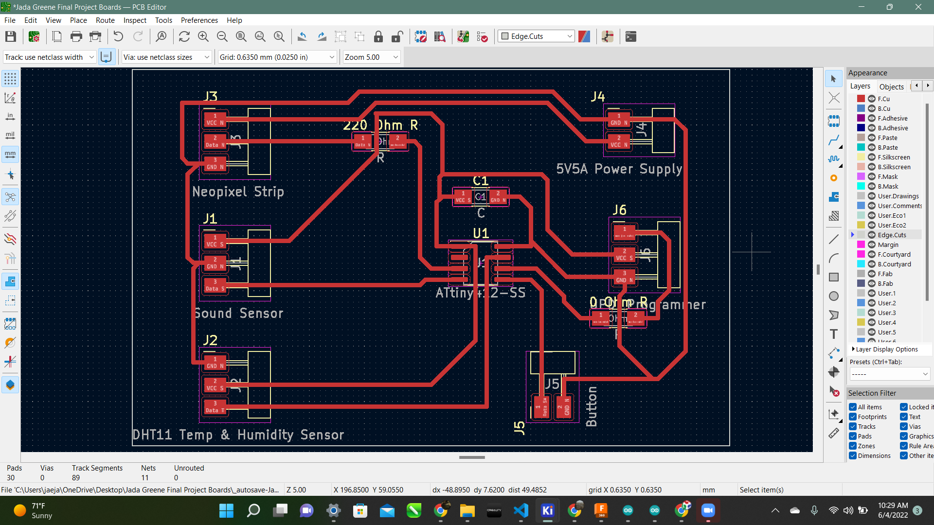
Now it was time to create my own board after getting it to work on just simply the arduino So I started in KiCAD. In my schematic I used an:
-
Attiny412
-
3 Pin Headers x4
-
2 Pin Headers x2
-
Capacitor
-
220Ohm Resistor
-
0Ohm Resistor
I created four 3 pin headers for the sound sensor, temp sensor, neopixels, and the UPDI for the Attiny. The two 2 pin headers are for the power supply and the button. The 220 Ohm Resistor is for the Neopixels and the 0 Ohm is just so I could have a trace going underneath it.

I uploaded the Jtag2updi Code to the arduino so I could make it a programmer. Then I tried to upload the code but I get the error “Error compiling for board Attiny412 w/Optiboot” I have no idea what this meant so I looked it up and found this site. Then I realized I am not even supposed to be using the optiboot option at all so I changed my board to just the attiny412 option without optiboot.
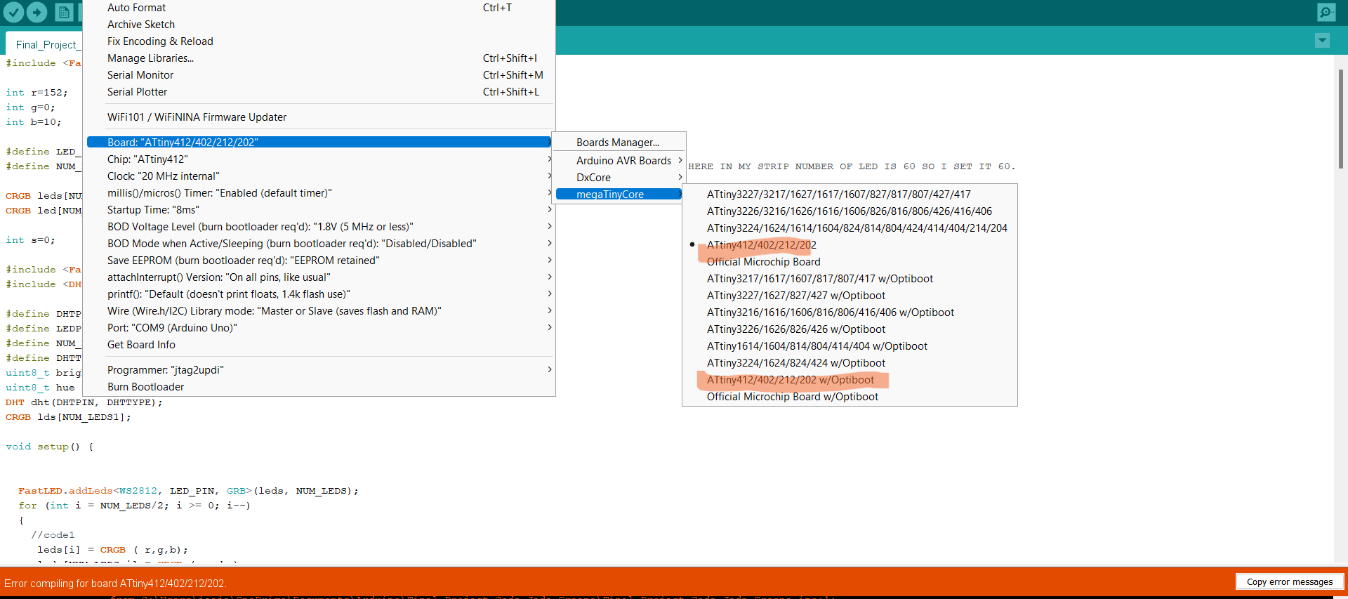
But then I still got the error “Error compiling for board Attiny412”. I was very lost so I talked with my instructor and he let me know it was because I was using “FastLED.h” library. That library does NOT work for Attiny412’s. So I did some research and found “tinyNeoPixel.h” Library. You can go here to download that library. I installed that and that got rid of the compiling error!! Although that brought up a new error. This one says
CRGB does not name a type
I did some more research and talked to my instructor. I believe it’s because that is not the correct color values for the new “tinyNeoPixel” library. I found this sample code on this site
#include <tinyNeoPixel_Static.h>
#define NUMLEDS 100
byte pixels[NUMLEDS * 3];
tinyNeoPixel leds = tinyNeoPixel(NUMLEDS, PIN_PA6, NEO_GRB, pixels);
void setup() {
  pinMode(PIN_PA6, OUTPUT);
  leds.setPixelColor(0, 255, 0, 0); // first LED full RED
  leds.show();                   // LED turns on.
}
void loop() {/* empty loop */}
This is the correct color values for the tinyNeoPixel library but now I need to figure out how to incorporate it into the code and replace the CRGB’s.
Regression
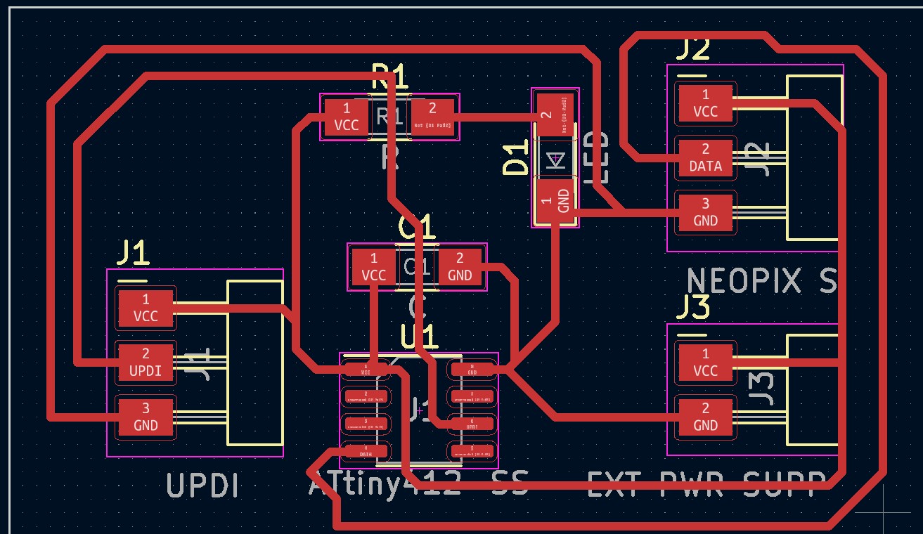
I am getting frustrated with this code so I am taking a step back and taking time to truly understand what I am doing. I already designed a board during output week that connects the programmer to the Neopixel strips through an Attiny. Now I am taking that a step further. I realized that with the board I made previously above that the programmer would have to be plugged into my computer so the Attiny would get power. That is a problem because it has to be INSIDE of my lamp it cant be plugged into my computer. So I started the design of a new board that would just contain these things:
-
3 Pin Header for Neopixels
-
3 Pin Header for UPDI Programmer
-
2 Pin Header for Power Supply
-
Power LED for Attiny412
-
330 Ohm Resistor for Power LED
-
1 uF Capacitor for Attiny412
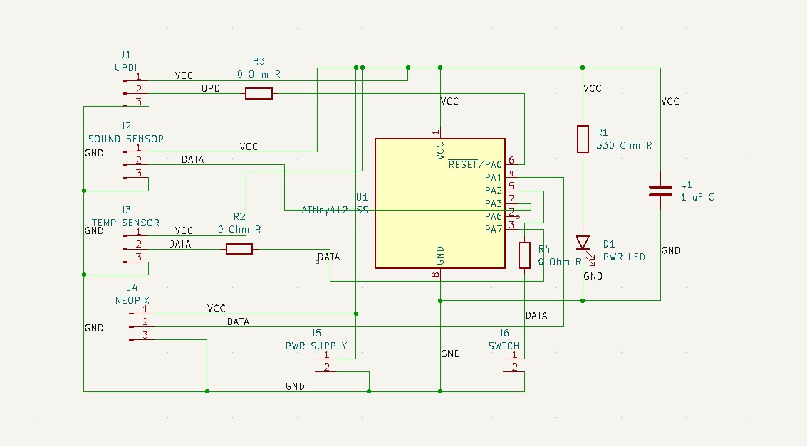
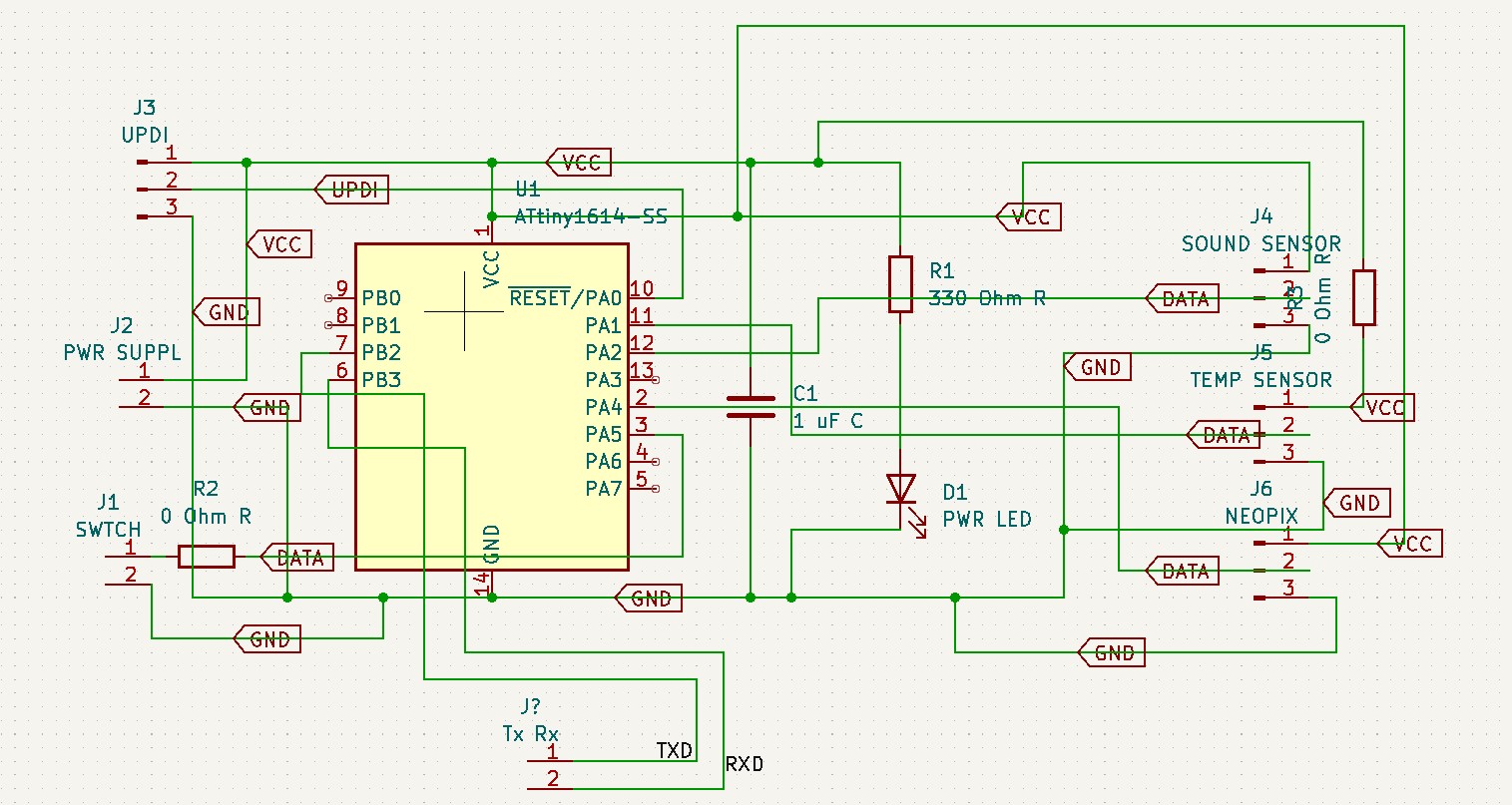
This is how the schematic looked after it was all connected:

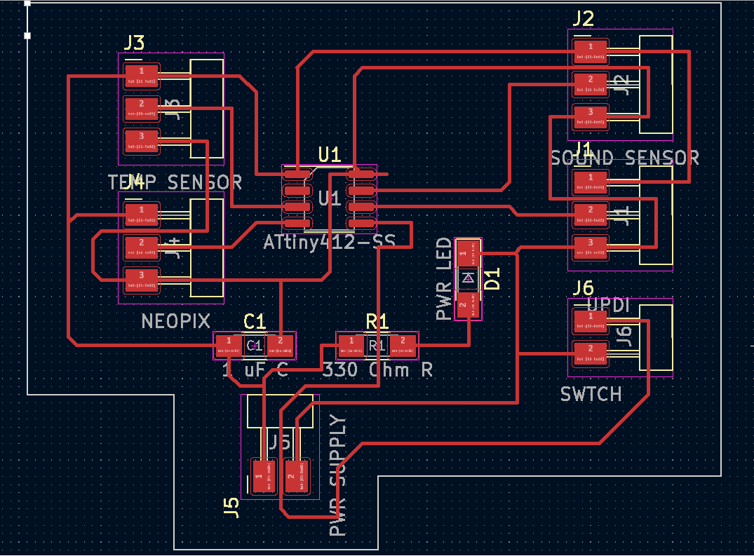
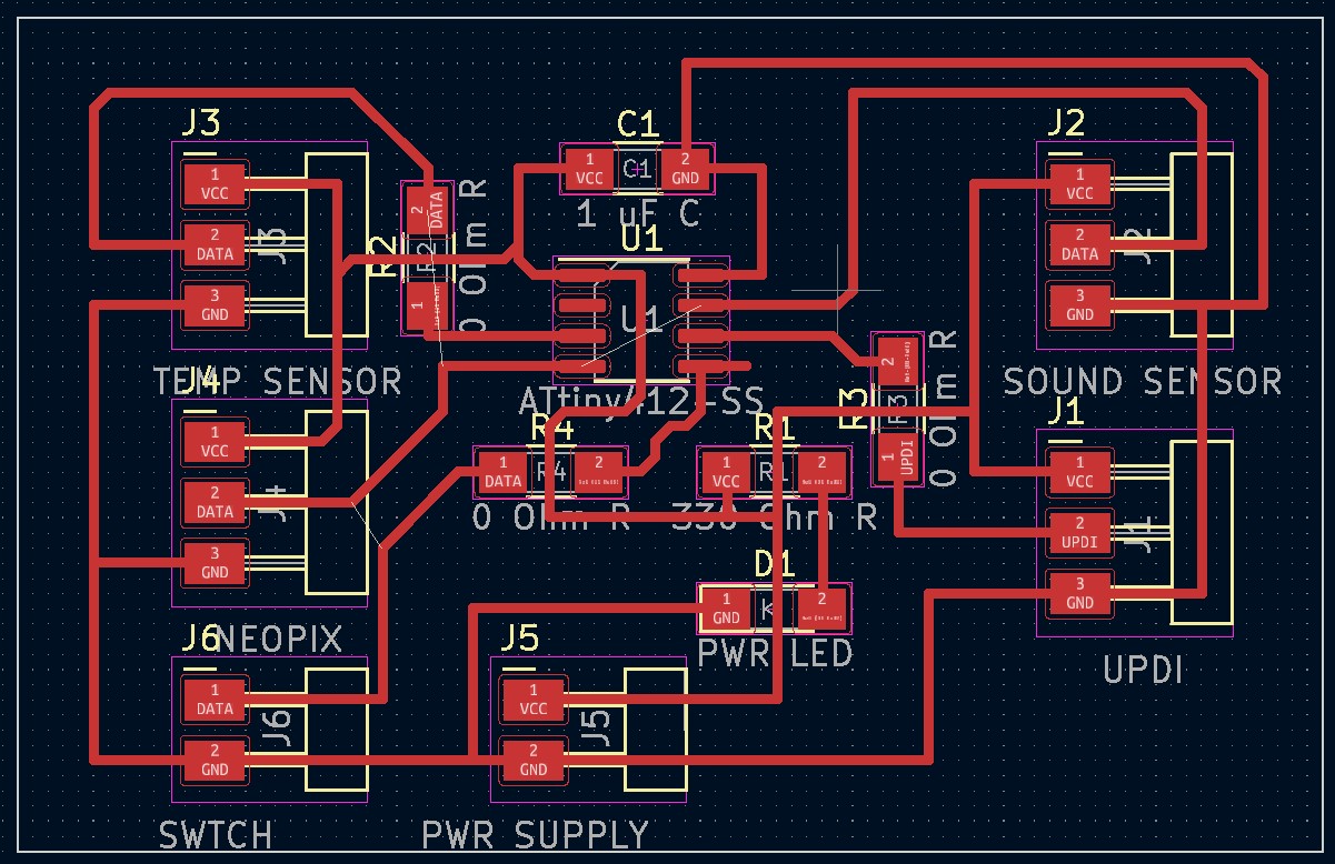
What I did differently here was connect the power from the power supply to the attiny so it shared a ground AND power. This is how the board looked:
Don’t forget to add labels to your schematic so it is easy to read the board. It also helps with soldering and connecting wires! So with this board I milled it out pretty smoothly then started connecting all the wires. I plugged in the programmer and the power LED turned on as I expected.
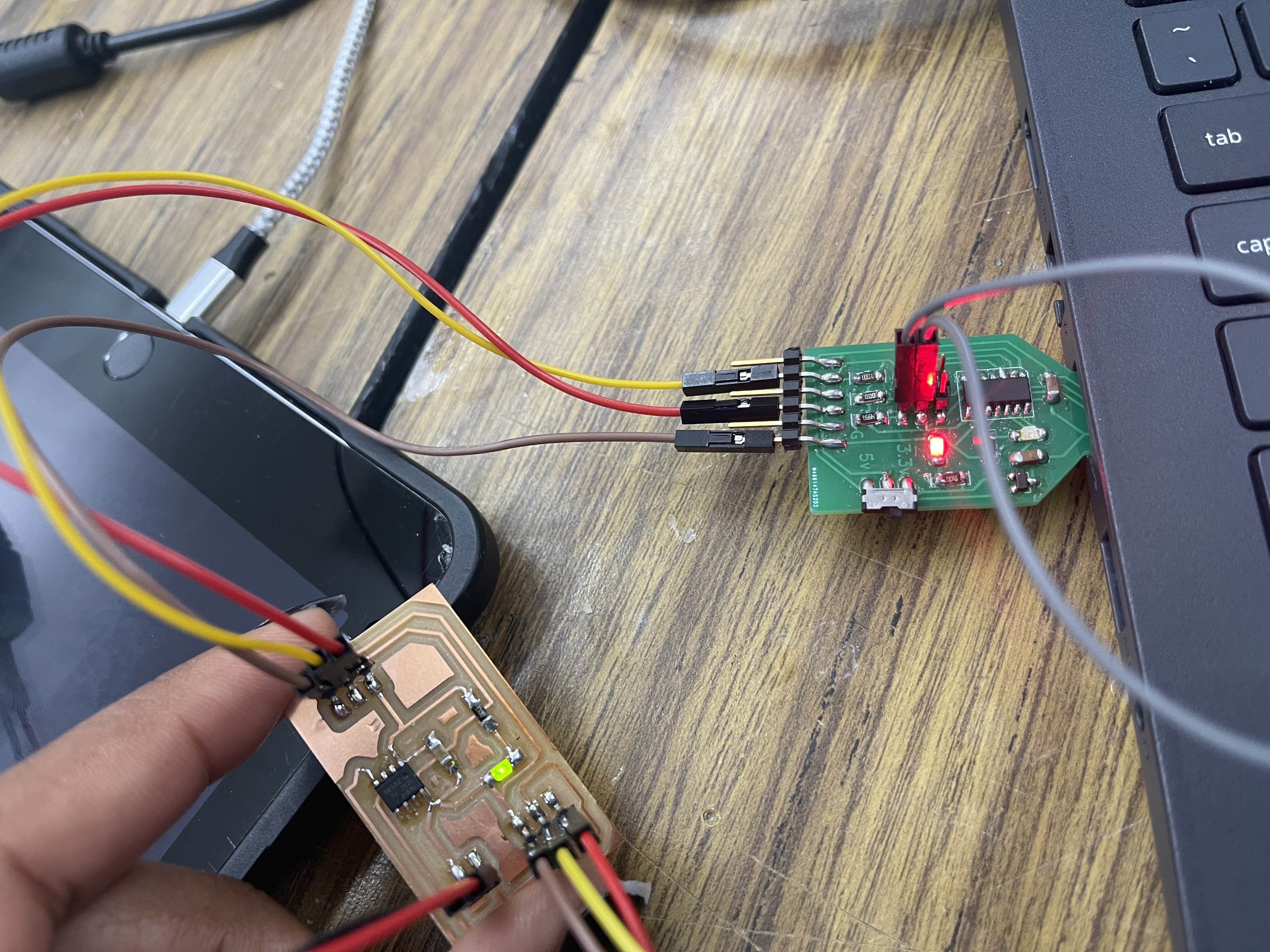
Then here was the moment of truth. I unplugged the programmer and plugged in the power supply. Then to my dismay the power LED turned on too!! It worked! Although when you have the external power supply plugged in DO NOT have the programmer connected to the board AT ALL. The board will start smoking a little. Mine did not fry but it smoked just a bit. So have it disconnected from your board ENTIRELY.
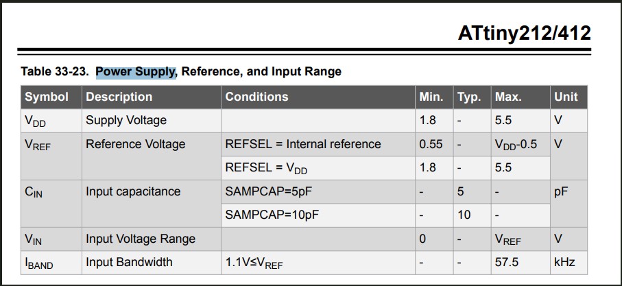
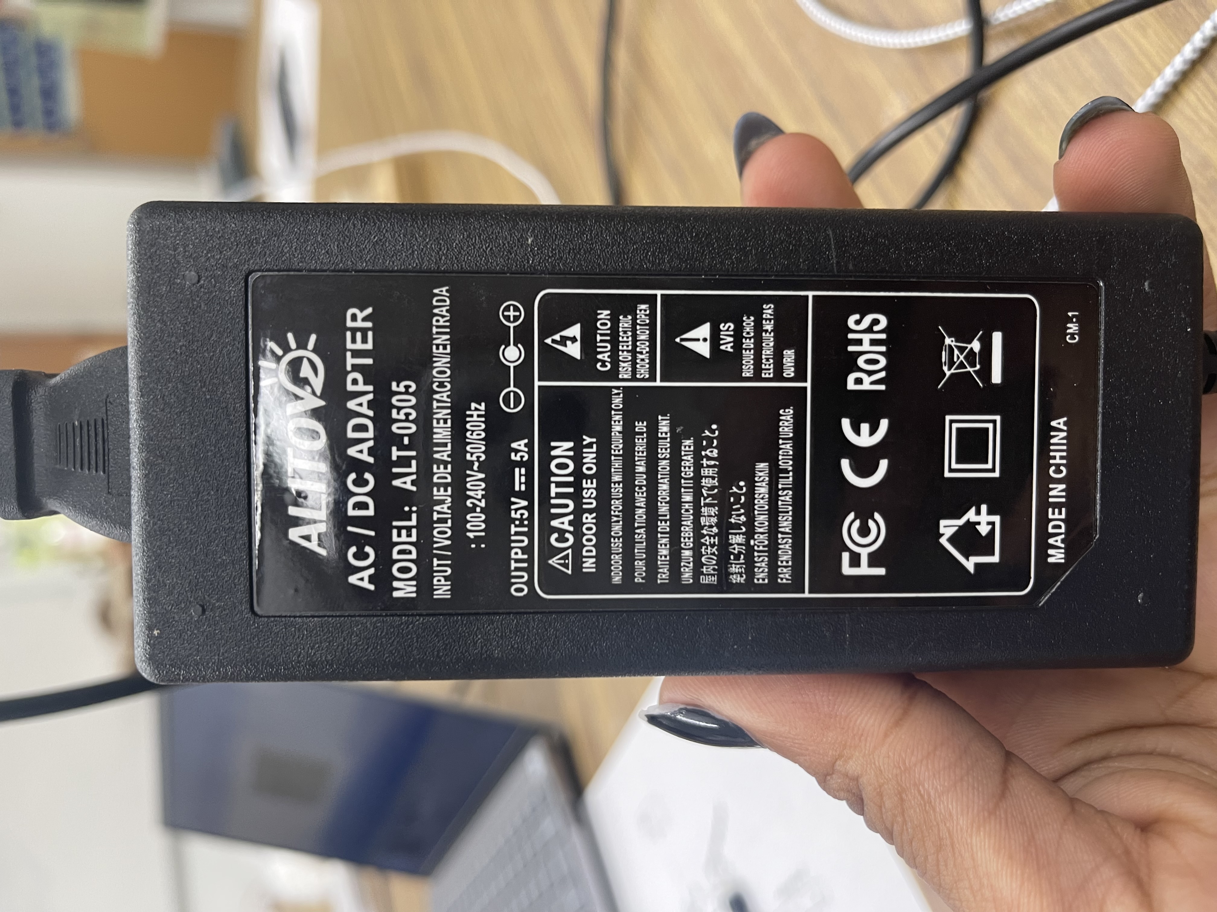
Also Note that I am using a 5V5A Power Supply. I found on the Attiny412 Datasheet on page 425 that the Attiny does not take anymore than 5.5 Volts. So do not connect a power supply with any higher of a voltage or you run the risk of frying the chip completely.
Next step was getting the Neopixels to run. So I unplugged the external power supply and rewired the programmer back in and used the Tiny Neopixel Strand test code Found here:
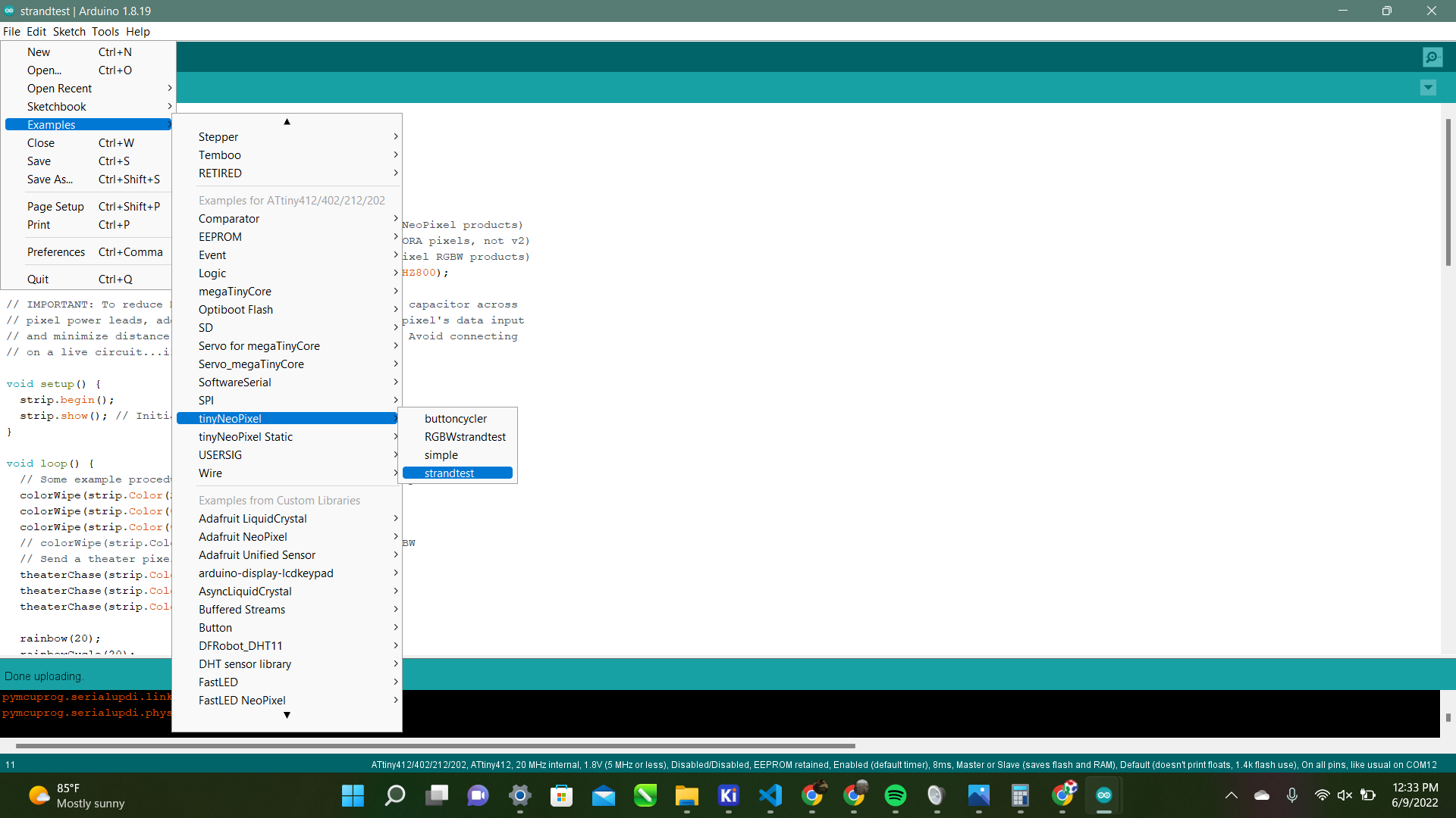
Here is the code:
#include <tinyNeoPixel.h>

#define PIN 2

// Parameter 1 = number of pixels in strip
// Parameter 2 = Arduino pin number (most are valid)
// Parameter 3 = pixel type
//   NEO_GRB     Pixels are wired for GRB bitstream (most NeoPixel products)
//   NEO_RGB     Pixels are wired for RGB bitstream (v1 FLORA pixels, not v2)
//   NEO_RGBW    Pixels are wired for RGBW bitstream (NeoPixel RGBW products)
tinyNeoPixel strip = tinyNeoPixel(10, PIN, NEO_GRB + NEO_KHZ800);

// IMPORTANT: To reduce NeoPixel burnout risk, add 1000 uF capacitor across
// pixel power leads, add 300 - 500 Ohm resistor on first pixel's data input
// and minimize distance between Arduino and first pixel.  Avoid connecting
// on a live circuit...if you must, connect GND first.

void setup() {
  strip.begin();
  strip.show(); // Initialize all pixels to 'off'
}

void loop() {
  // Some example procedures showing how to display to the pixels:
  colorWipe(strip.Color(255, 0, 0), 50); // Red
  colorWipe(strip.Color(0, 255, 0), 50); // Green
  colorWipe(strip.Color(0, 0, 255), 50); // Blue
  // colorWipe(strip.Color(0, 0, 0, 255), 50); // White RGBW
  // Send a theater pixel chase in...
  theaterChase(strip.Color(127, 127, 127), 50); // White
  theaterChase(strip.Color(127, 0, 0), 50); // Red
  theaterChase(strip.Color(0, 0, 127), 50); // Blue

  rainbow(20);
  rainbowCycle(20);
  theaterChaseRainbow(50);
}

// Fill the dots one after the other with a color
void colorWipe(uint32_t c, uint8_t wait) {
  for (uint16_t i = 0; i < strip.numPixels(); i++) {
    strip.setPixelColor(i, c);
    strip.show();
    delay(wait);
  }
}

void rainbow(uint8_t wait) {
  uint16_t i, j;

  for (j = 0; j < 256; j++) {
    for (i = 0; i < strip.numPixels(); i++) {
      strip.setPixelColor(i, Wheel((i + j) & 255));
    }
    strip.show();
    delay(wait);
  }
}

// Slightly different, this makes the rainbow equally distributed throughout
void rainbowCycle(uint8_t wait) {
  uint16_t i, j;

  for (j = 0; j < 256 * 5; j++) { // 5 cycles of all colors on wheel
    for (i = 0; i < strip.numPixels(); i++) {
      strip.setPixelColor(i, Wheel(((i * 256 / strip.numPixels()) + j) & 255));
    }
    strip.show();
    delay(wait);
  }
}

// Theatre-style crawling lights.
void theaterChase(uint32_t c, uint8_t wait) {
  for (int j = 0; j < 10; j++) { // do 10 cycles of chasing
    for (int q = 0; q < 3; q++) {
      for (uint16_t i = 0; i < strip.numPixels(); i = i + 3) {
        strip.setPixelColor(i + q, c);  // turn every third pixel on
      }
      strip.show();

      delay(wait);

      for (uint16_t i = 0; i < strip.numPixels(); i = i + 3) {
        strip.setPixelColor(i + q, 0);      // turn every third pixel off
      }
    }
  }
}

// Theatre-style crawling lights with rainbow effect
void theaterChaseRainbow(uint8_t wait) {
  for (int j = 0; j < 256; j++) {   // cycle all 256 colors in the wheel
    for (int q = 0; q < 3; q++) {
      for (uint16_t i = 0; i < strip.numPixels(); i = i + 3) {
        strip.setPixelColor(i + q, Wheel((i + j) % 255)); // turn every third pixel on
      }
      strip.show();

      delay(wait);

      for (uint16_t i = 0; i < strip.numPixels(); i = i + 3) {
        strip.setPixelColor(i + q, 0);      // turn every third pixel off
      }
    }
  }
}

// Input a value 0 to 255 to get a color value.
// The colours are a transition r - g - b - back to r.
uint32_t Wheel(byte WheelPos) {
  WheelPos = 255 - WheelPos;
  if (WheelPos < 85) {
    return strip.Color(255 - WheelPos * 3, 0, WheelPos * 3);
  }
  if (WheelPos < 170) {
    WheelPos -= 85;
    return strip.Color(0, WheelPos * 3, 255 - WheelPos * 3);
  }
  WheelPos -= 170;
  return strip.Color(WheelPos * 3, 255 - WheelPos * 3, 0);
}
I programmed it with my programmer just fine then again, it was the moment of truth. I COMPLETELY unplugged my programmer from my milled board and put it off to the side. Then I connected my external power supply to the board and Voila!! It worked!! Here is the video:
Now that I have that done I feel like I’m growing steps to truly understanding my final project. Next step is adding my sensors to the board above and get that running!
Redesigning
Now I am redesigning the board with the external power supply connected so it will be able to power everything through the lamp. I used the same components as before just remembered to wire it with the ground and power connected. This is how my schematic looked:
and this was my first board:
As you can see I was trying to avoid having to use 0 Ohm Resistors by wiring the traces in between the headers. I thought if I just used the .0005 Milling bit it would be alright. Although it turned out like this:

So I went back to the drawing board a redesigned it the right way. Here is how that turned out:
This looked good now it was time to hook everything up. I knew it was good because as soon as I plugged the programmer in the power LED and the light on the sound sensor turned on. Then I did a basic strand test which worked well. Then I tried a slightly larger code and was getting an error compiling to the board.
I was confused because I had just uploaded a simple and strand test successfully so I didn’t know what was wrong. I tried a larger example code and that didn’t work either. I asked my teacher and he said it was a memory issue. My 412 did not have enough memory to intake the big codes and large libraries I was pushing in. That means I had to get a new chip. I was very frustrated because I had just milled this new board and now I needed to change it and completely redesign it. So instead of a 412 I used an Attiny1614. I looked through the datasheet and that should be ok. So I went back over to KiCAD to start redesigning. This is how my schematic looked:
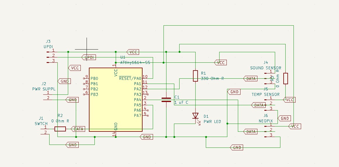
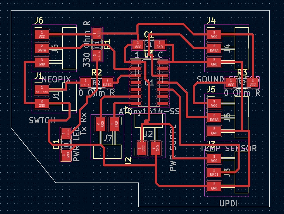
This is how the board turned out:

This looked good so I milled that out. It turned out well so I soldered on all the components including the new 1614 chip. Then it was time to get back to my code. I did a simple strand test and it worked again. Then I made sure that it all worked with an external power supply:
Then I was trying my big code but I was still getting errors. I then decided to break the code down to see if I could get certain parts working so I started with the sound sensor code. I used the code from the sound sensor above and changed it to the tinyNeoPixel library. This was a little tough to do because I kept getting syntax errors but from all the coding I have been doing recently I knew generally how to resolve those. Also here on the tinyNeoPixel creators git page he explains that, “Adafruit one to be readily understood, simple, with one purpose that it handles capably, and extensively commented, especially the assembly.” So he based the tinyNeopixel library off of the Adafruit_NeoPixel library which is probably why is was easier to modify. Then after hacking down on all the errors I finally got the code to verify! This is the code:
//#include <Adafruit_NeoPixel.h>
#include <tinyNeoPixel.h>
//#define NUMLEDS 100


#define N_PIXELS  5  // Number of pixels you are using
#define MIC_PIN   9  // Microphone is attached to Trinket GPIO #2/Gemma D2 (A1)
#define LED_PIN    0  // NeoPixel LED strand is connected to GPIO #0 / D0
#define DC_OFFSET  0  // DC offset in mic signal - if unusure, leave 0
#define NOISE     100  // Noise/hum/interference in mic signal
#define SAMPLES   5  // Length of buffer for dynamic level adjustment
#define TOP       (N_PIXELS +1) // Allow dot to go slightly off scale
// Comment out the next line if you do not want brightness control or have a Gemma
#define POT_PIN    3  // if defined, a potentiometer is on GPIO #3 (A3, Trinket only)


byte
  peak      = 0,      // Used for falling dot
  dotCount  = 0,      // Frame counter for delaying dot-falling speed
  volCount  = 0;      // Frame counter for storing past volume data

int
  vol[SAMPLES],       // Collection of prior volume samples
  lvl       = 10,     // Current "dampened" audio level
  minLvlAvg = 0,      // For dynamic adjustment of graph low & high
  maxLvlAvg = 512;

tinyNeoPixel strip = tinyNeoPixel(N_PIXELS, LED_PIN, NEO_GRB);
//Adafruit_NeoPixel  strip = Adafruit_NeoPixel(N_PIXELS, LED_PIN, NEO_GRB + NEO_KHZ800);

void setup() {
  //memset(vol, 0, sizeof(vol));
  memset(vol,0,sizeof(int)*SAMPLES);//Thanks Neil!
  strip.begin();
}
void loop() {
  uint8_t  i;
  uint16_t minLvl, maxLvl;
  int      n, height;
  n   = analogRead(MIC_PIN);                 // Raw reading from mic
  n   = abs(n - 512 - DC_OFFSET);            // Center on zero
  n   = (n <= NOISE) ? 0 : (n - NOISE);      // Remove noise/hum
  lvl = ((lvl * 7) + n) >> 3;    // "Dampened" reading (else looks twitchy)

  // Calculate bar height based on dynamic min/max levels (fixed point):
  height = TOP * (lvl - minLvlAvg) / (long)(maxLvlAvg - minLvlAvg);

  if(height < 0L)       height = 0;      // Clip output
  else if(height > TOP) height = TOP;
  if(height > peak)     peak   = height; // Keep 'peak' dot at top

// if POT_PIN is defined, we have a potentiometer on GPIO #3 on a Trinket
//    (Gemma doesn't have this pin)
  uint8_t bright = 255;
#ifdef POT_PIN
   bright = analogRead(POT_PIN);  // Read pin (0-255) (adjust potentiometer
                                  //   to give 0 to Vcc volts
#endif
  strip.setBrightness(bright);    // Set LED brightness (if POT_PIN at top
                                  //  define commented out, will be full)
  // Color pixels based on rainbow gradient
  for(i=0; i<N_PIXELS; i++) {
    if(i >= height)
       strip.setPixelColor(i,   0,   0, 0);
    else
       strip.setPixelColor(i,Wheel(map(i,0,strip.numPixels()-1,30,150)));
    }

   strip.show(); // Update strip

  vol[volCount] = n;                      // Save sample for dynamic leveling
  if(++volCount >= SAMPLES) volCount = 0; // Advance/rollover sample counter

  // Get volume range of prior frames
  minLvl = maxLvl = vol[0];
  for(i=1; i<SAMPLES; i++) {
    if(vol[i] < minLvl)      minLvl = vol[i];
    else if(vol[i] > maxLvl) maxLvl = vol[i];
  }
  // minLvl and maxLvl indicate the volume range over prior frames, used
  // for vertically scaling the output graph (so it looks interesting
  // regardless of volume level).  If they're too close together though
  // (e.g. at very low volume levels) the graph becomes super coarse
  // and 'jumpy'...so keep some minimum distance between them (this
  // also lets the graph go to zero when no sound is playing):
  if((maxLvl - minLvl) < TOP) maxLvl = minLvl + TOP;
  minLvlAvg = (minLvlAvg * 63 + minLvl) >> 6; // Dampen min/max levels
  maxLvlAvg = (maxLvlAvg * 63 + maxLvl) >> 6; // (fake rolling average)
}

// Input a value 0 to 255 to get a color value.
// The colors are a transition r - g - b - back to r.
uint32_t Wheel(byte WheelPos) {
  if(WheelPos < 85) {
   return strip.Color(WheelPos * 3, 255 - WheelPos * 3, 0);
  } else if(WheelPos < 170) {
   WheelPos -= 85;
   return strip.Color(255 - WheelPos * 3, 0, WheelPos * 3);
  } else {
   WheelPos -= 170;
   return strip.Color(0, WheelPos * 3, 255 - WheelPos * 3);
  }
}
And now it was time to plug it in. I was extremely nervous because I wasn’t sure if it was going to work. So I plugged it and here was the result:
It worked!! I was extremely happy because I’ve been having a lot of losses and problems with my codes recently this was the win I needed to help keep me motivated. After this worked I was feeling lucky so I went back to my main code. I again got a better understanding by reading through the tinyNeoPixel libraries git page and also comparing my code to the example codes from the tinyNeoPixel library to help me modify mine. After hours of doing that I finally got it to compile with no errors. I almost couldn’t believe it. After about a week working on just this code, I got it to compile. I was about to do a backflip I was so happy. Now again it was the time to test it out. I plugged in my programmer and made sure all my wires were right. Then I uploaded the code. I was even more nervous than before because if this works then that is the last step to my project besides assembly. I uploaded the code and it successfully uploaded to the board! Although the board did nothing. I knew it was too good to be true. The board did not respond at all there was no indicator that the code was even functioning. I took a bit hit because I thought after my code was modified I was in the clear. How wrong I was. This is the code that successfully uploaded I don’t want to call it functioning because it is not:
#include <tinyNeoPixel.h>
#include <DHT.h>

#define DHTPIN 8 // Data pin for DHT
#define DHTTYPE DHT11
#define N_PIXELS  5  // Number of pixels you are using
#define MIC_PIN   9  // Microphone is attached to Trinket GPIO #2/Gemma D2 (A1)
#define LED_PIN    0  // NeoPixel LED strand is connected to GPIO #0 / D0
#define DC_OFFSET  0  // DC offset in mic signal - if unusure, leave 0
#define NOISE     100  // Noise/hum/interference in mic signal
#define SAMPLES   5  // Length of buffer for dynamic level adjustment
#define TOP       (N_PIXELS +1) // Allow dot to go slightly off scale
// Comment out the next line if you do not want brightness control or have a Gemma
#define POT_PIN    3  // if defined, a potentiometer is on GPIO #3 (A3, Trinket only)

byte
  peak      = 0,      // Used for falling dot
  dotCount  = 0,      // Frame counter for delaying dot-falling speed
  volCount  = 0;      // Frame counter for storing past volume data

int
  vol[SAMPLES],       // Collection of prior volume samples
  lvl       = 10,     // Current "dampened" audio level
  minLvlAvg = 0,      // For dynamic adjustment of graph low & high
  maxLvlAvg = 512;

  uint8_t brightness = 255;
uint8_t hue = 0;
uint8_t t;
tinyNeoPixel strip = tinyNeoPixel(N_PIXELS, LED_PIN, NEO_GRB);
uint32_t Wheel(byte WheelPos) {
  if(WheelPos < 85) {
   return strip.Color(WheelPos * 3, 255 - WheelPos * 3, 0);
  } else if(WheelPos < 170) {
   WheelPos -= 85;
   return strip.Color(255 - WheelPos * 3, 0, WheelPos * 3);
  } else {
   WheelPos -= 170;
   return strip.Color(0, WheelPos * 3, 255 - WheelPos * 3);
  }
}
DHT dht(DHTPIN, DHTTYPE);
tinyNeoPixel lds[N_PIXELS];
//tinyNeoPixel strip = tinyNeoPixel(NUM_LEDS, LEDPIN, NEO_GRB + NEO_KHZ800);


void setup() {

  //memset(vol, 0, sizeof(vol));
  memset(vol,0,sizeof(int)*SAMPLES);//Thanks Neil!
  strip.begin();


  Serial.begin(9600);
  Serial.println("DHTxx test!");
  dht.begin();
// tinyNeoPixel<WS2812B, LEDPIN, GRB>(lds, NUM_LEDS);

}
void loop() {
  int switchvalue = digitalRead(3);
 Serial.println(switchvalue);
delay(100);

  if(switchvalue== HIGH){
   uint8_t  i;
  uint16_t minLvl, maxLvl;
  int      n, height;
  n   = analogRead(MIC_PIN);                 // Raw reading from mic
  n   = abs(n - 512 - DC_OFFSET);            // Center on zero
  n   = (n <= NOISE) ? 0 : (n - NOISE);      // Remove noise/hum
  lvl = ((lvl * 7) + n) >> 3;    // "Dampened" reading (else looks twitchy)

  // Calculate bar height based on dynamic min/max levels (fixed point):
  height = TOP * (lvl - minLvlAvg) / (long)(maxLvlAvg - minLvlAvg);

  if(height < 0L)       height = 0;      // Clip output
  else if(height > TOP) height = TOP;
  if(height > peak)     peak   = height; // Keep 'peak' dot at top

// if POT_PIN is defined, we have a potentiometer on GPIO #3 on a Trinket
//    (Gemma doesn't have this pin)
  uint8_t bright = 255;
#ifdef POT_PIN
   bright = analogRead(POT_PIN);  // Read pin (0-255) (adjust potentiometer
                                  //   to give 0 to Vcc volts
#endif
  strip.setBrightness(bright);    // Set LED brightness (if POT_PIN at top
                                  //  define commented out, will be full)
  // Color pixels based on rainbow gradient
  for(i=0; i<N_PIXELS; i++) {
    if(i >= height)
       strip.setPixelColor(i,   0,   0, 0);
    else
       strip.setPixelColor(i,Wheel(map(i,0,strip.numPixels()-1,30,150)));
    }

   strip.show(); // Update strip

  vol[volCount] = n;                      // Save sample for dynamic leveling
  if(++volCount >= SAMPLES) volCount = 0; // Advance/rollover sample counter

  // Get volume range of prior frames
  minLvl = maxLvl = vol[0];
  for(i=1; i<SAMPLES; i++) {
    if(vol[i] < minLvl)      minLvl = vol[i];
    else if(vol[i] > maxLvl) maxLvl = vol[i];
  }
  // minLvl and maxLvl indicate the volume range over prior frames, used
  // for vertically scaling the output graph (so it looks interesting
  // regardless of volume level).  If they're too close together though
  // (e.g. at very low volume levels) the graph becomes super coarse
  // and 'jumpy'...so keep some minimum distance between them (this
  // also lets the graph go to zero when no sound is playing):
  if((maxLvl - minLvl) < TOP) maxLvl = minLvl + TOP;
  minLvlAvg = (minLvlAvg * 63 + minLvl) >> 6; // Dampen min/max levels
  maxLvlAvg = (maxLvlAvg * 63 + maxLvl) >> 6; // (fake rolling average)

} //end if
else {

 // Wait between measurements.
  delay(250);
  // Reading temperature or humidity takes about 250 milliseconds!
  // Read temperature as Celsius (the default)
  t = dht.readTemperature();

  if (t >= 30) {
    hue = 0;
  }
  if (t < 30 && t >= 29) {
    hue = 50;
  }
  if (t >= 27 && t < 29) {
    hue = 85;
  }
  if (t < 27 && t >= 26) {
    hue = 120;
  }
  if (t < 26) {
    hue = 160;
  }

  for (uint8_t i = 0; i < N_PIXELS; i++) {
    lds[i] = tinyNeoPixel(hue, 255, brightness);
  }
  strip.show();

  // Check if any reads failed and exit early (to try again).
  if (isnan(t) ) {
    Serial.println("Failed to read from DHT sensor!");
    return;
  }
/*
  Serial.print("Temperature: ");
  Serial.print(t);
  Serial.print(" *C ");
  Serial.print("Hue: ");
  Serial.print(hue);
  Serial.println();*/


}
}//end loop
This failing was a huge motivational hit I feel so close yet so far. Only a few more days until my presentation and I have faulty electronics. I thought maybe the Neopixels were broken but I uploaded another strand test and that worked perfect. I was so confused and frustrated because I didn’t understand the problem. I took a step back and tried to figure something out. I saw in a video online that I should try to get something to print to the serial monitor to see if the board is alright. So I found this serial monitor code:
void setup() {
  Serial.begin(9600); // open the serial port at 9600 bps:
}

void loop() {
  // print labels
  Serial.print("NO FORMAT");  // prints a label
  Serial.print("\t");         // prints a tab

  Serial.print("DEC");
  Serial.print("\t");

  Serial.print("HEX");
  Serial.print("\t");

  Serial.print("OCT");
  Serial.print("\t");

  Serial.print("BIN");
  Serial.println();        // carriage return after the last label

  for (int x = 0; x < 64; x++) { // only part of the ASCII chart, change to suit
    // print it out in many formats:
    Serial.print(x);       // print as an ASCII-encoded decimal - same as "DEC"
    Serial.print("\t\t");  // prints two tabs to accomodate the label lenght

    Serial.print(x, DEC);  // print as an ASCII-encoded decimal
    Serial.print("\t");    // prints a tab

    Serial.print(x, HEX);  // print as an ASCII-encoded hexadecimal
    Serial.print("\t");    // prints a tab

    Serial.print(x, OCT);  // print as an ASCII-encoded octal
    Serial.print("\t");    // prints a tab

    Serial.println(x, BIN);  // print as an ASCII-encoded binary
    // then adds the carriage return with "println"
    delay(200);            // delay 200 milliseconds
  }
  Serial.println();        // prints another carriage return
}
I tried it on the arduino first and that worked perfectly fine. Then I hooked it up to my board. There was nothing. Nothing was printing to the serial monitor. I was confused on what was going on. I looked it up and found someone with the same problem. This is the solution they were given.
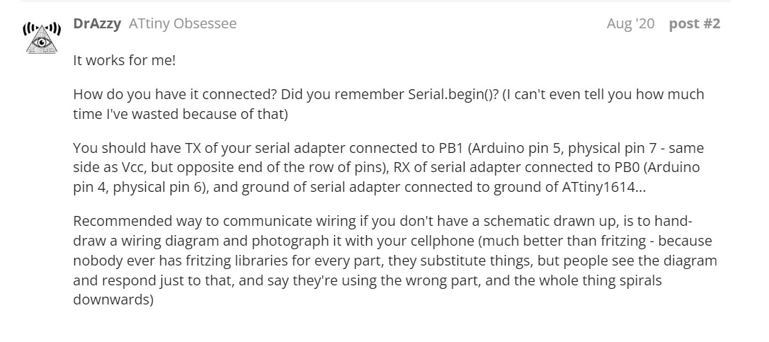
This was surprising to me and also a little confusing. Did I have to have it connected to the Tx and Rx pins which were those bottom pins? But what part was supposed to be connected to that Are they supposed to be connected to the UPDI? I had so many questions and this explanation just confused me further. I am more a visual learned so I wished they would have included the schematic so their explanation was a little easier to follow.
Looking back on that explanation I just had a revelation. I think I am supposed to be connecting the Tx and Rx Pins on the chip to the Tx and Rx pins of the programmer. I was confused because I always looking at this layout of the programmer to wire my boards up:
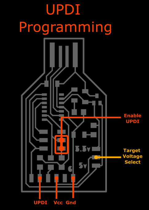
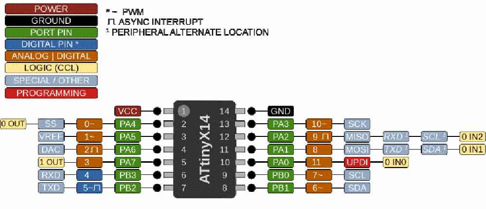
Then I remember that there are three other pins that are unlabeled. Two of those have to be a Tx and Rx pin. So I hunt down the full pinout for the programmer. Then I found this here:

This was the full pinout that I needed! I noticed that the UPDI pin and the Rx pin were in the same place though which didn’t make sense because on the 1614 the Rx pin is pin 7 and the UPDI is pin 10.
Now I am even more confused. I just need this code to work. … I have returned with the answer. I asked around and realized I needed a header to the Tx and Rx pins on my 1614. Then I need to change my programmer to an FTDI. So back to KiCAD again!
So now here’s the schematic with the Tx and Rx pins added to a 2 pin header
Here is how the board turned out:
I connected the Tx and Rx pins to the board and then ran a simple serial monitor code again. I changed the COM port to the port of the FTDI and there!:
This worked!! This is perfect so I ran the codes for my temperature sensor and it started printing values. This is great so I can work on the sensitivity. Although now I need to work on getting the switch working before changing the sensitivity. So I worked with a teacher in my lab Adam Durrett and realized I made the most stupid mistake. I needed my switch connected back to power for it to work. So I made the the 2 pin header a 3 pin header and connected one of the pins to power then retried the final project code. To my surprise this worked! I was about to cry. I was so happy that it was actually switching in between sensors. This was my final part.
For more info on this check week 15
Sensitivity
Next it was time to figure out the sensitivity for the sensor. This was not super hard for the temperature sensor I just had to read the serial monitor and see what the average temperature in the room was and build off of that. So I connected the FTDI and read the temperature sensor very easily and got that working well within the labs temperature. Then I had to do it for the sound sensor. Although the sound sensor code was not as easy as to read the values and change the code because there was a lot of math involved. I did not fully understand this so I researched the equations in the code then I found this:
#include <Adafruit_NeoPixel.h>
#include <math.h>

#define N_PIXELS  16  // Number of pixels in strand
#define MIC_PIN   A9  // Microphone is attached to this analog pin
#define LED_PIN    6  // NeoPixel LED strand is connected to this pin
#define SAMPLE_WINDOW   10  // Sample window for average level
#define PEAK_HANG 24 //Time of pause before peak dot falls
#define PEAK_FALL 4 //Rate of falling peak dot
#define INPUT_FLOOR 10 //Lower range of analogRead input
#define INPUT_CEILING 300 //Max range of analogRead input, the lower the value the more sensitive (1023 = max)

byte peak = 16;      // Peak level of column; used for falling dots
unsigned int sample;

byte dotCount = 0;  //Frame counter for peak dot
byte dotHangCount = 0; //Frame counter for holding peak dot

Adafruit_NeoPixel strip = Adafruit_NeoPixel(N_PIXELS, LED_PIN, NEO_GRB + NEO_KHZ800);

void setup()
{
  // This is only needed on 5V Arduinos (Uno, Leonardo, etc.).
  // Connect 3.3V to mic AND TO AREF ON ARDUINO and enable this
  // line.  Audio samples are 'cleaner' at 3.3V.
  // COMMENT OUT THIS LINE FOR 3.3V ARDUINOS (FLORA, ETC.):
  //  analogReference(EXTERNAL);

  // Serial.begin(9600);
  strip.begin();
  strip.show(); // Initialize all pixels to 'off'

}

void loop()
{
  unsigned long startMillis= millis();  // Start of sample window
  float peakToPeak = 0;   // peak-to-peak level

  unsigned int signalMax = 0;
  unsigned int signalMin = 1023;
  unsigned int c, y;


  // collect data for length of sample window (in mS)
  while (millis() - startMillis < SAMPLE_WINDOW)
  {
    sample = analogRead(MIC_PIN);
    if (sample < 1024)  // toss out spurious readings
    {
      if (sample > signalMax)
      {
        signalMax = sample;  // save just the max levels
      }
      else if (sample < signalMin)
      {
        signalMin = sample;  // save just the min levels
      }
    }
  }
  peakToPeak = signalMax - signalMin;  // max - min = peak-peak amplitude

  // Serial.println(peakToPeak);


  //Fill the strip with rainbow gradient
  for (int i=0;i<=strip.numPixels()-1;i++){
    strip.setPixelColor(i,Wheel(map(i,0,strip.numPixels()-1,30,150)));
  }


  //Scale the input logarithmically instead of linearly
  c = fscale(INPUT_FLOOR, INPUT_CEILING, strip.numPixels(), 0, peakToPeak, 2);


  if(c < peak) {
    peak = c;        // Keep dot on top
    dotHangCount = 0;    // make the dot hang before falling
  }
  if (c <= strip.numPixels()) { // Fill partial column with off pixels
    drawLine(strip.numPixels(), strip.numPixels()-c, strip.Color(0, 0, 0));
  }

  // Set the peak dot to match the rainbow gradient
  y = strip.numPixels() - peak;

  strip.setPixelColor(y-1,Wheel(map(y,0,strip.numPixels()-1,30,150)));

  strip.show();

  // Frame based peak dot animation
  if(dotHangCount > PEAK_HANG) { //Peak pause length
    if(++dotCount >= PEAK_FALL) { //Fall rate
      peak++;
      dotCount = 0;
    }
  }
  else {
    dotHangCount++;
  }
}

//Used to draw a line between two points of a given color
void drawLine(uint8_t from, uint8_t to, uint32_t c) {
  uint8_t fromTemp;
  if (from > to) {
    fromTemp = from;
    from = to;
    to = fromTemp;
  }
  for(int i=from; i<=to; i++){
    strip.setPixelColor(i, c);
  }
}


float fscale( float originalMin, float originalMax, float newBegin, float
newEnd, float inputValue, float curve){

  float OriginalRange = 0;
  float NewRange = 0;
  float zeroRefCurVal = 0;
  float normalizedCurVal = 0;
  float rangedValue = 0;
  boolean invFlag = 0;


  // condition curve parameter
  // limit range

  if (curve > 10) curve = 10;
  if (curve < -10) curve = -10;

  curve = (curve * -.1) ; // - invert and scale - this seems more intuitive - postive numbers give more weight to high end on output
  curve = pow(10, curve); // convert linear scale into lograthimic exponent for other pow function

  /*
   Serial.println(curve * 100, DEC);   // multply by 100 to preserve resolution
   Serial.println();
   */

  // Check for out of range inputValues
  if (inputValue < originalMin) {
    inputValue = originalMin;
  }
  if (inputValue > originalMax) {
    inputValue = originalMax;
  }

  // Zero Refference the values
  OriginalRange = originalMax - originalMin;

  if (newEnd > newBegin){
    NewRange = newEnd - newBegin;
  }
  else
  {
    NewRange = newBegin - newEnd;
    invFlag = 1;
  }

  zeroRefCurVal = inputValue - originalMin;
  normalizedCurVal  =  zeroRefCurVal / OriginalRange;   // normalize to 0 - 1 float

  // Check for originalMin > originalMax  - the math for all other cases i.e. negative numbers seems to work out fine
  if (originalMin > originalMax ) {
    return 0;
  }

  if (invFlag == 0){
    rangedValue =  (pow(normalizedCurVal, curve) * NewRange) + newBegin;

  }
  else     // invert the ranges
  {
    rangedValue =  newBegin - (pow(normalizedCurVal, curve) * NewRange);
  }

  return rangedValue;
}


// Input a value 0 to 255 to get a color value.
// The colours are a transition r - g - b - back to r.
uint32_t Wheel(byte WheelPos) {
  if(WheelPos < 85) {
    return strip.Color(WheelPos * 3, 255 - WheelPos * 3, 0);
  }
  else if(WheelPos < 170) {
    WheelPos -= 85;
    return strip.Color(255 - WheelPos * 3, 0, WheelPos * 3);
  }
  else {
    WheelPos -= 170;
    return strip.Color(0, WheelPos * 3, 255 - WheelPos * 3);
  }
}
This is an adjustable sound sensor code. This code I was able to change the sensitivity of the sensor much more accurately than the last with math I understood. So after modifying this, I was essentially done with the code! I inserted this new sound sensor code into my if/else statement of my final code and uploaded it. After hacking through a few easy syntax errors I was done!! Here is the Final complete working code:
Final Working Code
//Temp Sensor Code Start

#include <tinyNeoPixel.h>
#include <DHT.h>

#define DHTPIN 8 // Data pin for DHT
#define LEDPIN 0 //Data Pin for LEDs
#define NUM_LEDS 40 //Number of LEDs
#define DHTTYPE DHT11
uint8_t brightness = 255;
uint8_t hue = 0;
float t;

DHT dht(DHTPIN, DHTTYPE);
tinyNeoPixel lds[NUM_LEDS];
tinyNeoPixel strip = tinyNeoPixel(NUM_LEDS, LEDPIN, NEO_RGB);

//Sound Sensor Code Start

#include <math.h>

#define N_PIXELS  40  // Number of pixels in strand
#define MIC_PIN   9  // Microphone is attached to this analog pin
#define LED_PIN    0  // NeoPixel LED strand is connected to this pin
#define SAMPLE_WINDOW   10  // Sample window for average level
#define PEAK_HANG 24 //Time of pause before peak dot falls
#define PEAK_FALL 4 //Rate of falling peak dot
#define INPUT_FLOOR 100 //Lower range of analogRead input
#define INPUT_CEILING 300 //Max range of analogRead input, the lower the value the more sensitive (1023 = max)

byte peak = 16;      // Peak level of column; used for falling dots
unsigned int sample;

byte dotCount = 0;  //Frame counter for peak dot
byte dotHangCount = 0; //Frame counter for holding peak dot

// tinyNeoPixel strip = tinyNeoPixel(N_PIXELS, LED_PIN, NEO_GRB + NEO_KHZ800);

void setup() {

// Temp Sensor Setup Starts

 Serial.begin(9600);
  Serial.println("DHTxx test!");
  dht.begin();
  strip.begin();

// Sound Sensor Setup Starts

// This is only needed on 5V Arduinos (Uno, Leonardo, etc.).
  // Connect 3.3V to mic AND TO AREF ON ARDUINO and enable this
  // line.  Audio samples are 'cleaner' at 3.3V.
  // COMMENT OUT THIS LINE FOR 3.3V ARDUINOS (FLORA, ETC.):
  //  analogReference(EXTERNAL);

  // Serial.begin(9600);
  strip.begin();
  strip.show(); // Initialize all pixels to 'off'

}
void loop(){
  if(digitalRead(1)== HIGH){
    // Wait between measurements.
    delay(250);
    // Reading temperature or humidity takes about 250 milliseconds!
    // Read temperature as Celsius (the default)
    t = dht.readTemperature();
    Serial.println(t);
    if (t > 27) {
      for (uint8_t i = 0; i < NUM_LEDS; i++) {
        strip.setPixelColor(i,   0,   255, 0);
      }
    }
    if (t < 25 && t <= 27) {
     for (uint8_t i = 0; i < NUM_LEDS; i++) {
        strip.setPixelColor(i,   123,   255, 0);
      }
    }
    if (t > 23 && t <= 25) {
      for (uint8_t i = 0; i < NUM_LEDS; i++) {
        strip.setPixelColor(i,   242,   255, 0);
      }
    }
    if (t <= 23 && t > 19) {
     for (uint8_t i = 0; i < NUM_LEDS; i++) {
        strip.setPixelColor(i,   208,   0, 255);
      }
    }
    if (t <= 19) {
      for (uint8_t i = 0; i < NUM_LEDS; i++) {
        strip.setPixelColor(i,   0,   0, 255);
      }
    }


    strip.show();

    // Check if any reads failed and exit early (to try again).
    if (isnan(t) ) {
      Serial.println("Failed to read from DHT sensor!");
      return;
    }
  /*
    Serial.print("Temperature: ");
    Serial.print(t);
    Serial.print(" *C ");
    Serial.print("Hue: ");
    Serial.print(hue);
    Serial.println();*/
  } //end if
  else {
 unsigned long startMillis= millis();  // Start of sample window
  float peakToPeak = 0;   // peak-to-peak level

  unsigned int signalMax = 0;
  unsigned int signalMin = 1023;
  unsigned int c, y;


  // collect data for length of sample window (in mS)
  while (millis() - startMillis < SAMPLE_WINDOW)
  {
    sample = analogRead(MIC_PIN);
    if (sample < 1024)  // toss out spurious readings
    {
      if (sample > signalMax)
      {
        signalMax = sample;  // save just the max levels
      }
      else if (sample < signalMin)
      {
        signalMin = sample;  // save just the min levels
      }
    }
  }
  peakToPeak = signalMax - signalMin;  // max - min = peak-peak amplitude

  // Serial.println(peakToPeak);


  //Fill the strip with rainbow gradient
  for (int i=0;i<=strip.numPixels()-1;i++){
    strip.setPixelColor(i,Wheel(map(i,0,strip.numPixels()-1,30,150)));
  }


  //Scale the input logarithmically instead of linearly
  c = fscale(INPUT_FLOOR, INPUT_CEILING, strip.numPixels(), 0, peakToPeak, 2);


  if(c < peak) {
    peak = c;        // Keep dot on top
    dotHangCount = 0;    // make the dot hang before falling
  }
  if (c <= strip.numPixels()) { // Fill partial column with off pixels
    drawLine(strip.numPixels(), strip.numPixels()-c, strip.Color(0, 0, 0));
  }

  // Set the peak dot to match the rainbow gradient
  y = strip.numPixels() - peak;

  strip.setPixelColor(y-1,Wheel(map(y,0,strip.numPixels()-1,30,150)));

  strip.show();

  // Frame based peak dot animation
  if(dotHangCount > PEAK_HANG) { //Peak pause length
    if(++dotCount >= PEAK_FALL) { //Fall rate
      peak++;
      dotCount = 0;
    }
  }
  else {
    dotHangCount++;
  }
}
}//end loop

//Used to draw a line between two points of a given color
void drawLine(uint8_t from, uint8_t to, uint32_t c) {
  uint8_t fromTemp;
  if (from > to) {
    fromTemp = from;
    from = to;
    to = fromTemp;
  }
  for(int i=from; i<=to; i++){
    strip.setPixelColor(i, c);
  }
}


float fscale( float originalMin, float originalMax, float newBegin, float
newEnd, float inputValue, float curve){

  float OriginalRange = 0;
  float NewRange = 0;
  float zeroRefCurVal = 0;
  float normalizedCurVal = 0;
  float rangedValue = 0;
  boolean invFlag = 0;


  // condition curve parameter
  // limit range

  if (curve > 10) curve = 10;
  if (curve < -10) curve = -10;

  curve = (curve * -.1) ; // - invert and scale - this seems more intuitive - postive numbers give more weight to high end on output
  curve = pow(10, curve); // convert linear scale into lograthimic exponent for other pow function

  /*
   Serial.println(curve * 100, DEC);   // multply by 100 to preserve resolution
   Serial.println();
   */

  // Check for out of range inputValues
  if (inputValue < originalMin) {
    inputValue = originalMin;
  }
  if (inputValue > originalMax) {
    inputValue = originalMax;
  }

  // Zero Refference the values
  OriginalRange = originalMax - originalMin;

  if (newEnd > newBegin){
    NewRange = newEnd - newBegin;
  }
  else
  {
    NewRange = newBegin - newEnd;
    invFlag = 1;
  }

  zeroRefCurVal = inputValue - originalMin;
  normalizedCurVal  =  zeroRefCurVal / OriginalRange;   // normalize to 0 - 1 float

  // Check for originalMin > originalMax  - the math for all other cases i.e. negative numbers seems to work out fine
  if (originalMin > originalMax ) {
    return 0;
  }

  if (invFlag == 0){
    rangedValue =  (pow(normalizedCurVal, curve) * NewRange) + newBegin;

  }
  else     // invert the ranges
  {
    rangedValue =  newBegin - (pow(normalizedCurVal, curve) * NewRange);
  }

  return rangedValue;
}


// Input a value 0 to 255 to get a color value.
// The colours are a transition r - g - b - back to r.
uint32_t Wheel(byte WheelPos) {
  if(WheelPos < 85) {
    return strip.Color(WheelPos * 3, 255 - WheelPos * 3, 0);
  }
  else if(WheelPos < 170) {
    WheelPos -= 85;
    return strip.Color(255 - WheelPos * 3, 0, WheelPos * 3);
  }
  else {
    WheelPos -= 170;
    return strip.Color(0, WheelPos * 3, 255 - WheelPos * 3);
  }
}
Week 17 - Wildcard Week
Two-Part Mold
For one of my wildcard projects I did my first two part mold. I thought this was a great way to include molding and casting into final project. I had no clue how to do a two part mold so it was exciting. I first started with viewing Kevin Kennedy’s Video on two part molds to help me. Then I used what I learned from that video to design this. In the model below I have the top piece at 50% opacity so you can see the visual structure of the mold.
Then I 3D printed this. Both pieces separately. The bottom piece took about 10 hours and the top took about 8. The prints turned out great. So I took some

The only things I would change is definitely how big the mold itself was. It could’ve been a much smaller box and the mold would have been fine but what I made was a waste of filament so I am redesigning it. The mold itself was nice I might make it a little thinner and bring it down from 3mm thick to 2mm or 1.5mm. Also the cast was a little tough to remove because the curves of the mold. I had to pry it out which cut the mold a bit but since its a flexible rubber material it didn’t sustain too much damage. Besides these factors that I am working on fixing, the mold as a whole turned out great and I was ecstatic over the successful mold.
No Specific Week
Laser Cutting
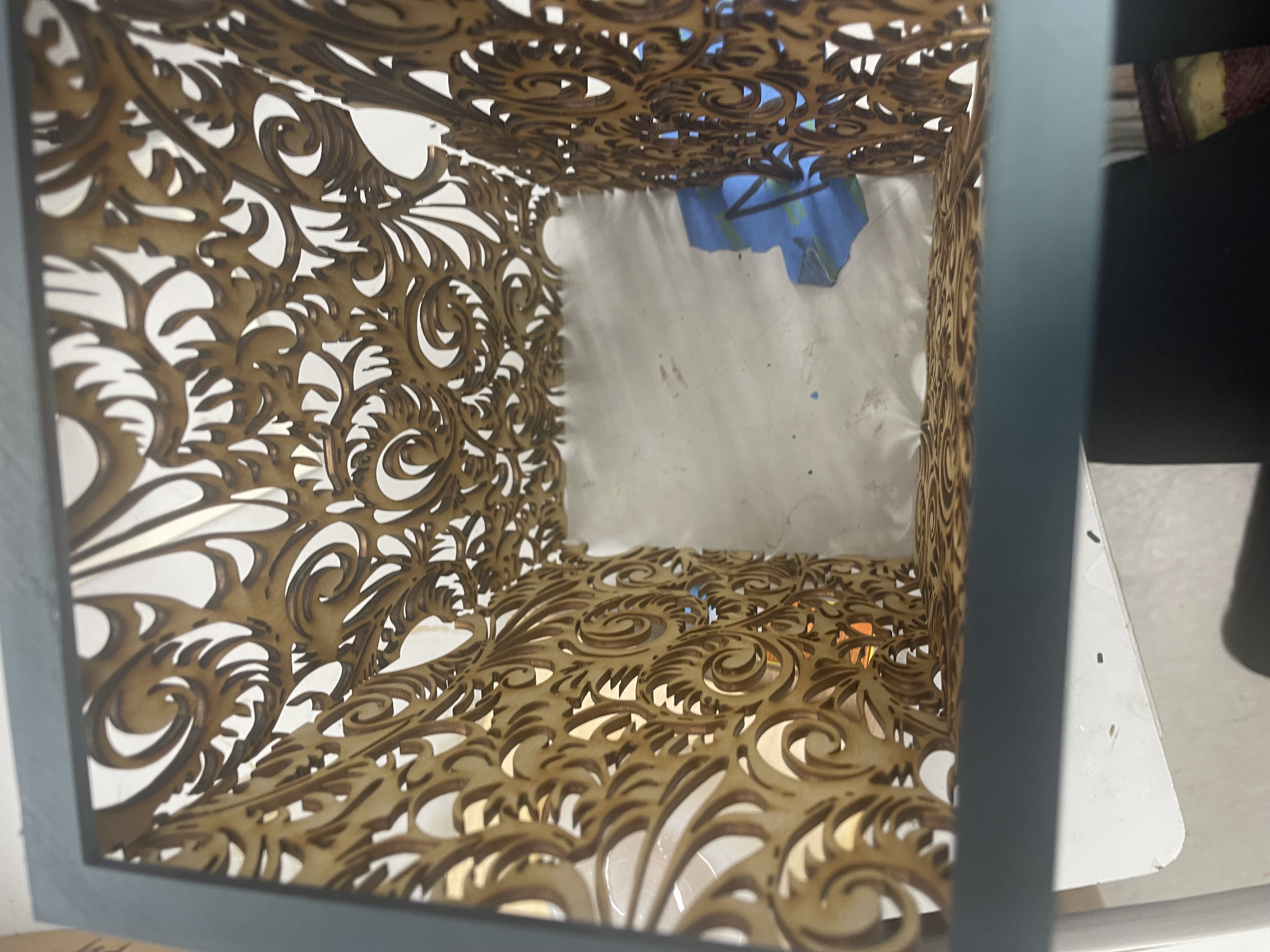
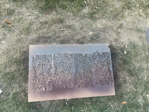
Floral Design
Here I started to create a design for my wood. I went to Corel Draw and started to design a paisley type pattern. I used the draw tool to draw this pattern. I practiced here on cardboard first.
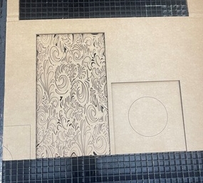

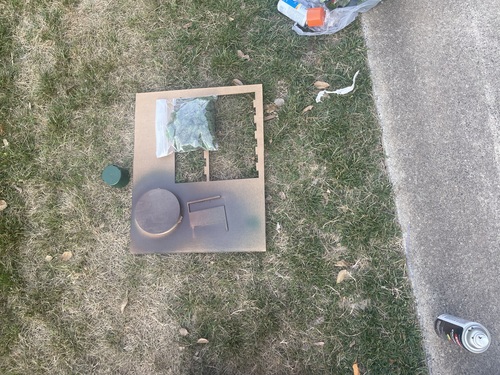
Base 3
I also created this in Corel Draw. It is just a 6.25”x6.25” square with a circle in the center so the casted semi circle can go over the neopixels and electronics. This was an extremely simple design. I just cut it out and sanded the corners to curve them like the bases were curved.

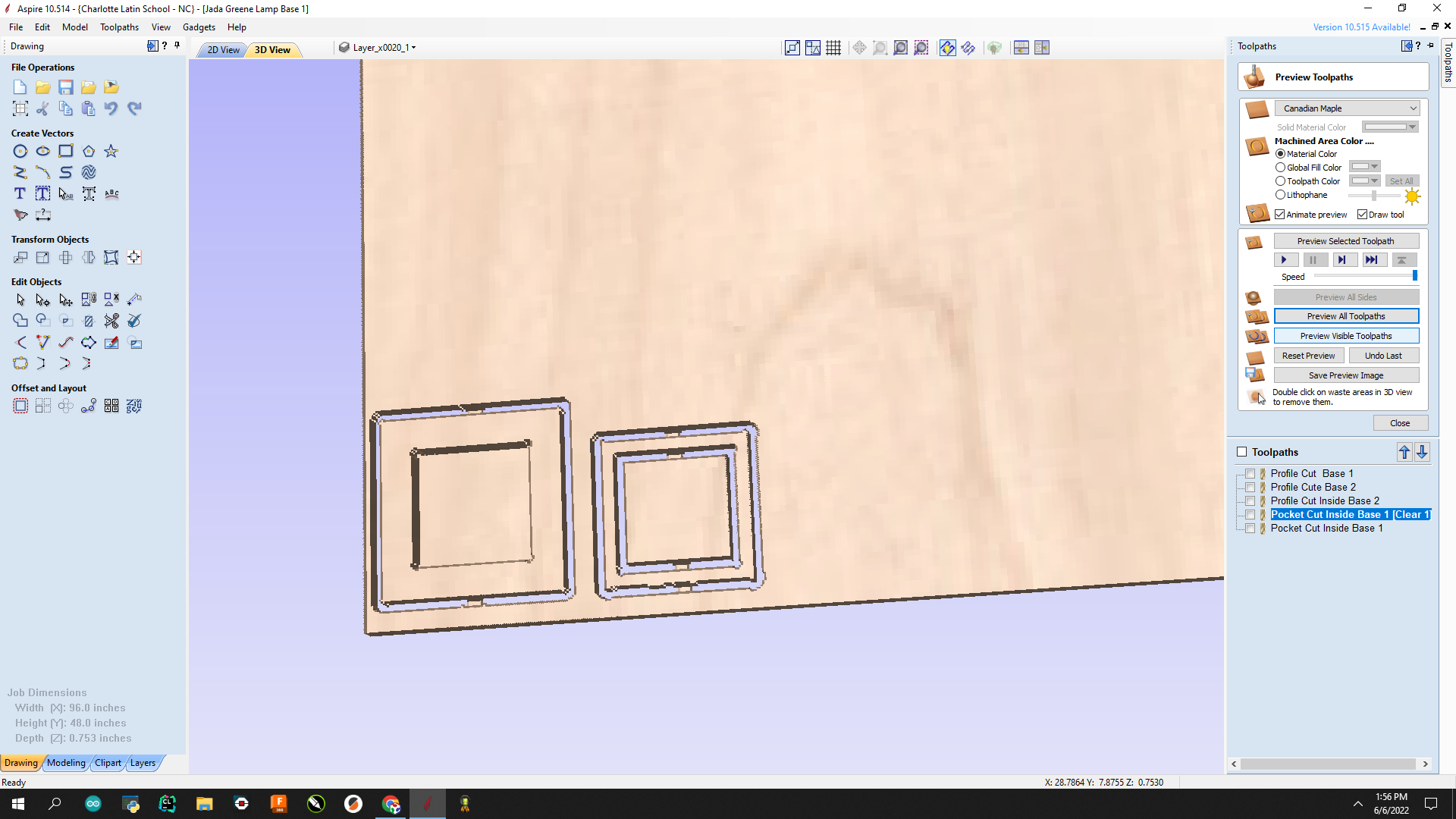
CNC Milling
I started to CNC Mill the base of my lamp. I first designed the base in Corel draw. Then I exported it and put it into Aspire as I did for CNC week. I first went to “Set Job dimensions and origin”. There I changed these settings:
-
Job Type: Single Sided
-
Job Size: W: 96.0” H: 48.0” Thickness: 0.753”
-
Z Zero Position: Machine Bed
-
XY Datum Position: Bottom Left
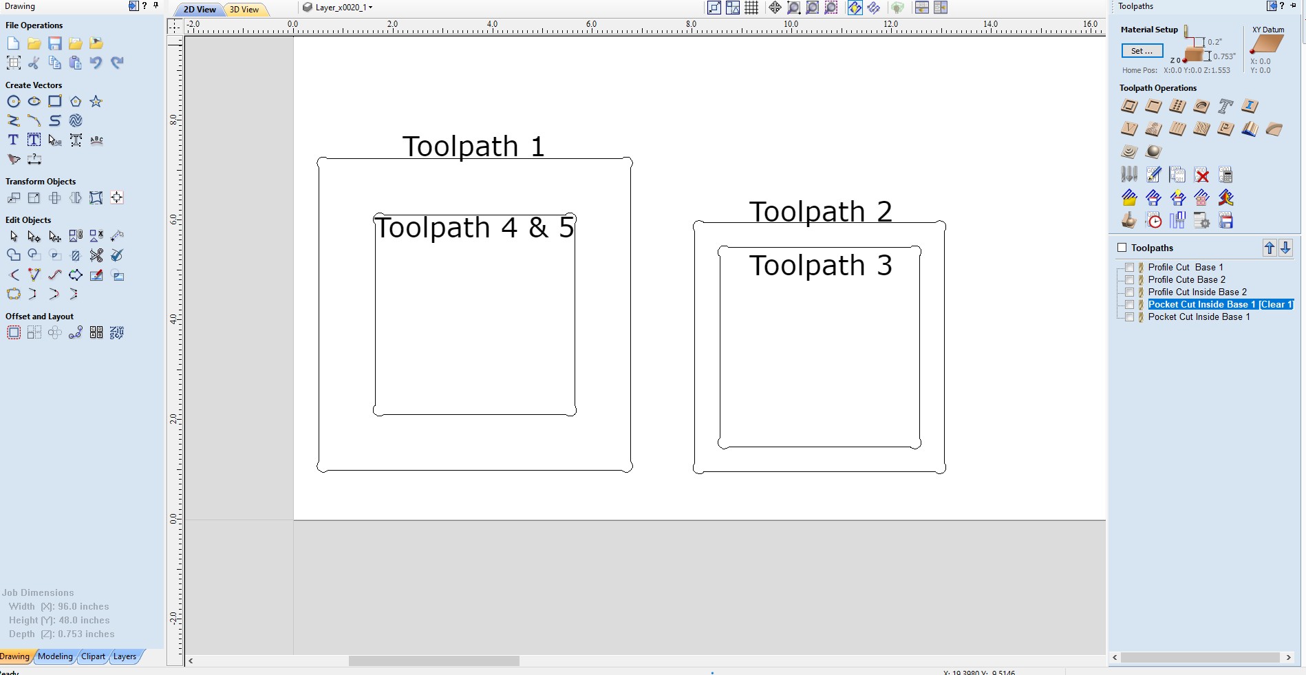
I had 5 Toolpaths in all.
Toolpath 1
My first toolpath was a Profile Cut. That means it cuts all the way through the wood. I set the start depth at 0.0” and the cut depth as 0.753” which is the thickness of my wood. Then I chose an “End Mill (1/4”)” As my tool. Then I changed the passes from 8 to 4 so it would cut 0.1883” with each pass. Then I chose the Machine Vector as “Outside/Right” in a climb direction. Then I added two tabs with the Length being 0.5 inches and the thickness being 0.125 inches. Then labeled it “Profile Cut Base 1”.
Toolpath 2
My second toolpath was also a Profile Cut. I set the start depth at 0.0” and the cut depth as 0.753” again. Then I chose an “End Mill (1/4”)” As my tool. Then I changed the passes from 8 to 4 so it would cut 0.1883” with each pass. Then I chose the Machine Vector as “Outside/Right” in a climb direction again because it is also an external cut. Then I added two tabs with the Length being 0.5 inches and the thickness being 0.125 inches. Then labeled it “Profile Cut Base 2”.
Toolpath 3
My third toolpath was a Profile Cut once again. I set the start depth at 0.0” and the cut depth as 0.753” again. Then I chose an “End Mill (1/4”)” As my tool. Then I changed the passes from 8 to 4 so it would cut 0.1883” with each pass. Then I chose the Machine Vector as “Inside/Left” in a climb direction this time because it was an internal cut on the inside of one of the pieces. Then I added two tabs with the Length being 0.5 inches and the thickness being 0.125 inches. Then labeled it “Profile Cut Inside Base 2”.
Toolpath 4 & 5
Lastly, These last two cuts were pocket cuts. Pocket cuts is when it does NOT cut all the way through the wood. I kept the start depth at 0.0” but the Cut depth is 0.55 inches so it is a pretty deep hole into the wood but not all the way through. I kept the tool as an End Mill (1/4”) bit. I had the passes set to 6 because I forgot to change it to 4 but it didn’t make much of difference it just took more time. Then I has it set to offset in the climbing direction. That is all that I needed for a pocket cut so after this I just labeled it “Pocket Cut Inside Base 1”. But for this pocket cut it splits into two because Aspire automatically added a finishing pass so the pocket turns out nice and clean. So toolpath 4 is the clearing pass and toolpath 5 is the finishing pass.
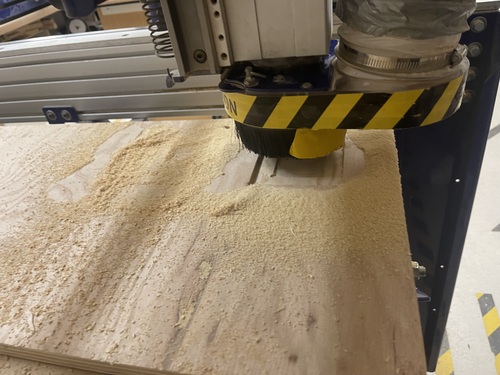
Next I load the wood onto the CNC Machine and secure it down onto the machine bed. I then go through the steps of the Machines workflow then start my cut. Although I did have to put the bit in, I learned how to do that during Machine week so that was pretty easy. Just be careful because the bit is very sharp. Next I started the machine:
With some sanding it turned out like this
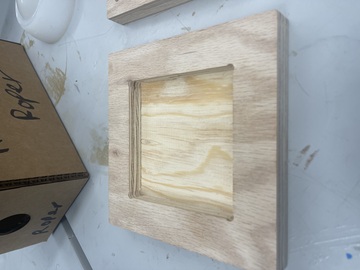


This turned out great I was very happy with the outcome.
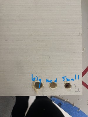
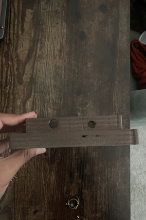
Drilling
Next I had to drill holes for my external power supply to run through and for my sound sensor so it won’t be trapped between blocks of wood. and could still accurately pick up sound. So I actually did not measure the cord or sensor mic but I learned a trick that if you hold up the right size bit to the cord or sensor it will be a perfect match. So after I found the correct size bits I got a small bit. I got a small bit to start so I wouldn’t split my wood. So I drilled two small holes then went in with the medium bit that fit the sound sensor perfectly. I did that for both holes then went in with the largest bit for the cord on one of the holes. This worked amazing and the holes turned out pretty nice. They are a little off center but they will be covered. Also the hole for the external power supply is also where the switch will be out of so it is convenient and still hidden.
3D Printing
For 3D printing I am 3D printing two pieces to hold all my laser cut side pieces together without glue. I went to fusion and designed this fairy simply design:
This has a ridge that will firmly hold all the sides of my lamp together like this:

Final Touches
Lastly, it was time to do what I do best; make this lamp beautiful! I was going for a vintage rustic look to match my desk:

So I started the lamp off with green spray paint at the top then faded it down. I then put the brown primer+paint over that so the green wouldn’t be as strong and noticeable. Then I added some bronze which gave it a nice sparkle and shine. I did that to all my pieces even the 3D printed ones.

Then I had the idea to put some greenery on it. I added some faux moss to the top of the 3d printed side holder.

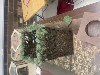
It turned out amazing. This is the final product of how it looked aesthetically:

Final Slide and Video
Click Here to see my final slide!
Click Here to watch my final video!
Final Note and Future Plans
I chose to keep my lamp easily disassemble-able so I can add more sensors in the future. I would love to add an internal clock so it can have a sunrise and sunset mode on it. I also would love to make different patters of sides so no matter what ‘vibe’ I am going for I can just easily take on and off the sides so I can switch it up! I am really happy I am done with the rough version of the project. What took me months to do I can do again in so much less time. I am ready to elevate this project. I also want to have a motion sensor to wave on and off the lamp in the future. I am so happy on how thus turned out. I feel like I personally came a very long way from when I started. I knew nothing about code and here I am now understanding, fixing and even writing my own. It is honestly unfathomable at some point how I got to this point but I am truly is happy I made it. I learned a crazy amount not even throughout all the weeks but this final project itself I learned so so much. I can read code, write code, I understand how to interface to read serial data. I learned how to do so much during this time and I can’t wait to continue this quest of knowledge even though this is ending now.
More info on this check week 19
Materials
Note: All these materials were found inside the lab. I did not have to purchase any of these items for my project.
Final Result Components
-
KY-037 Sound Sensor
-
DHT11 Temperature Sensor
-
SPDT Switch
-
Female to Female Wires
-
5V5A Power Supply
-
Final Board
Final Board Components
-
3 Pin Header for Neopixels
-
3 Pin Header for UPDI Programmer
-
3 Pin Header for Sound Sensor
-
3 Pin Header for Temperature Sensor
-
3 Pin Header for Switch
-
2 Pin Header for Power Supply
-
2 Pin Header for Tx and Rx Pins
-
Power LED for Attiny412
-
330 Ohm Resistor for Power LED
-
1 uF Capacitor for Attiny1614
-
3 0 Ohm Resistors for jumping
Lamp Components
-
1/8” Wood
-
3/4” Wood
-
Casted Hollow Semi-Sphere
-
3D Printed Lamp Holder
Aesthetic Components
-
Green Spray Paint
-
Dark Brown Spray Primer&Paint
-
Bronze Spray Paint
-
Faux Moss
Design Files

This work is licensed under a Creative Commons Attribution-NonCommercial-ShareAlike 4.0 International License.