11. Output devices
This week it output Devices. I want to do something for my final project so I am doing a neopixel strip as my output device.
Design
TinkerCAD
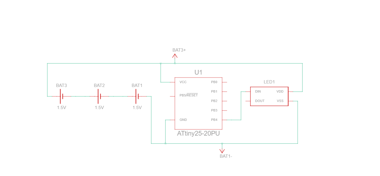
I first started designing my neopixels in Tinker Circuit. I added the Attiny85 because that is the only attiny that is available. Although on my final product I will be using an Attiny412. I then added a 4 neopixel strip, and 3 1.5V batteries. I also originally had a 499Ohm Resistor but I removed it because Neopixels have a built in resistor. So the final design came to look like this:

This was the view in schematic editor.
Then this was the code used in tinker circuit.
#include <Adafruit_NeoPixel.h>

#define PIN 4 // input pin Neopixel is attached to

#define NUMPIXELS      4// number of neopixels in strip

Adafruit_NeoPixel pixels = Adafruit_NeoPixel(NUMPIXELS, PIN, NEO_GRB + NEO_KHZ800);

int delayval = 100; // timing delay in milliseconds


void setup() {
  // Initialize the NeoPixel library.
  pixels.begin();

    //for (int i=0; i < NUMPIXELS; i++) {
    // pixels.Color takes RGB values, from 0,0,0 up to 255,255,255
    pixels.setPixelColor(0, pixels.Color(255, 0, 0));
    pixels.setPixelColor(1,pixels.Color(255, 255,0));
    pixels.setPixelColor(2,pixels.Color(255, 0, 255));
    pixels.setPixelColor(3,pixels.Color(0, 255, 255));

    // This sends the updated pixel color to the hardware.
    pixels.show();
}

void loop() {


}
KiCAD
After this was finished I started to design my board in KiCad. I made a new project and opened the schematic editor. On my schematic I have an Attiny412 Chip, and two 3 pin headers. I have one of the headers connected to GND, VCC, and pin 6 which is the UPDI pin on the attiny412. These headers will go from the Arduino tot he Attiny because the Attiny needs the UPDI. Then the other header connected to GND, VCC, and pin 4 as the data pin. These headers are connected to the Neopixel strip. This is my final schematic:

I then designed it in PCB editor. This was my first design. It is extremely messy and confusing but I did not realize that until it was time to start programming it. This was the original one:
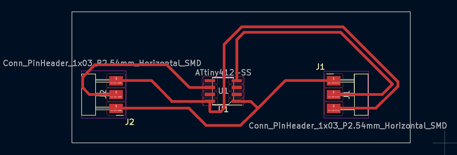
This is very bad it has the chip upside down, the pins in different directions and ultimately extremely confusing. This is the one I redesigned to re-mill:

This fixed a lot of the problems the chip is now right side up and the pins are both going VCC, UPDI/DATA, GND, in order.
Milling
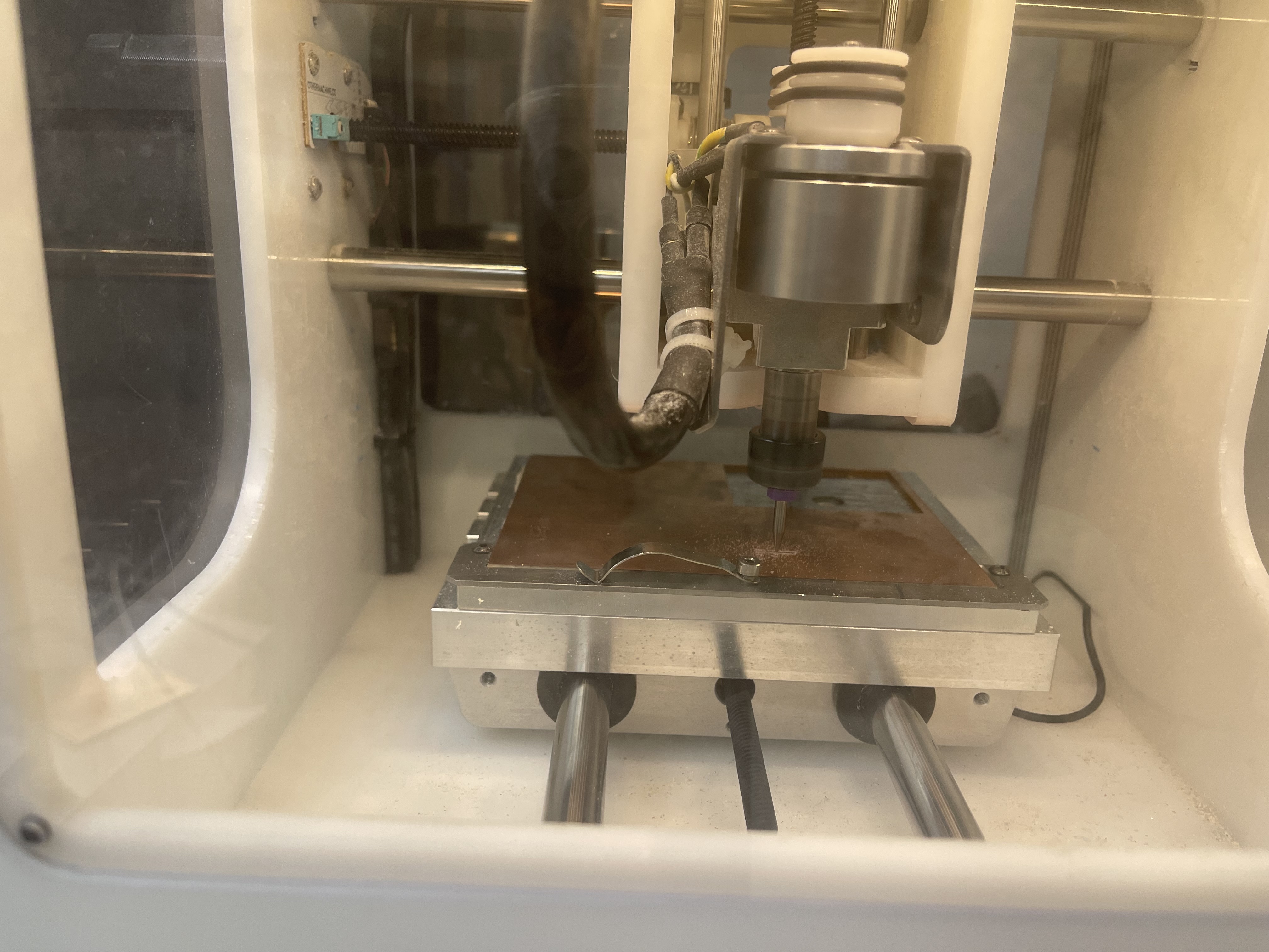
Unfortunately I originally milled my original PCB with the chip upside down and it was very confusing. I used a 1/64th Flat End Mill bit for the traces then a 1/32nd Flat End Mill bit for the Edge Cut. I then soldered on the Attiny412 Chip, and two 3 Pin headers. It turned out very nice like this:

I then soldered wires onto my NEopixel LED Strip. I stripped some female to female wires. I Stripped one side and soldered it onto the LED copper pads.
Programming
Next, the most challenging part for me, Programming. I first ran a simple blink code on my Arduino to make sure my arduino was broken or fried and it was not so that was good. Then I connected my Neopixel Strip to the arduino to check if my lights were working. I pot male to male wires in the lights to the board. I first was getting the error: “
Now it is time to use the board I milled (First board) to use as a programmer. I had to make my arduino a programmer again so I uploaded the “Jtag2UPDI” back onto the arduino I did this before in Week 7. I then started connecting wires. This is where I realized my first board was very poorly designed because it was extremely confusing to do the wiring. But after taking too long to have everything connected I ran another simple sketch and that did not work because I was confused on the pin outs and had it connected to 5 instead of 6. That’s when I truly realized I needed to redesign and re-mill a new board. But after I changed the pin it compiled but I got a new error:
avrdude: jtagmkII_initialize(): Cannot locate "flash" and "boot" memories in description
avrdude: jtagmkII_program_enable(): bad response to enter progmode command: RSP_NO_TARGET_POWER
avrdude: jtagmkII_program_enable(): bad response to enter progmode command: RSP_NO_TARGET_POWER
avrdude: jtagmkII_read_byte(): bad response to read memory command: RSP_NO_TARGET_POWER
avr_read(): error reading address 0x0000
    read operation not supported for memory "signature"
avrdude: error reading signature data for part "ATtiny412", rc=-2
avrdude: error reading signature data, rc=-2
avrdude: jtagmkII_program_disable(): bad response to leave progmode command: RSP_NO_TARGET_POWER
the selected serial port avrdude: jtagmkII_program_disable(): bad response to leave progmode command: RSP_NO_TARGET_POWER
 does not exist or your board is not connected
This means there is something wrong with my board. So now I am re-milling it. This turned out great. I had the chip right side up this time and the pins on the same side with the same pin outs so I wouldn’t get confused. I then tried again to turn my arduino to a programmer and that went smoothly. I just wanted to check that my LED’s still worked and they did. I connected my board and Reran my code through my arduino and it worked.
Next, it was time to use my SAMD11C programmer. I used Barbara Morrows Ice Programmer to make my SAMD into a programmer. I was very thankful because it was the last ICE in the lab. After getting my programmer set it was smooth sailing from there. I connected my SAMD to my board like this:

This worked well and I was very happy. I struggle greatly with programming so this was a big feat for me.
What I learned
I learned a lot this week. One of the most memorable things this week was sitting down with my instructor and figuring out not just why my board and lights and code worked but WHY it worked. He went through and explained the lines of code and what the purpose was and how it correlated to the pins. This was amazing because I knew what my stuff was and the function but not truly the science and logic behind how it works. Again, I struggles with this week and it took me longer than most people but it was all worth it to understand what I was doing instead of just “memorizing” what to do. This helped me work through the multitude of my errors and even help another one of my peers. That was the most rewarding feeling. I learned how to troubleshoot arduino code and more on the Attiny. I also learned how to read deeper and truly understand a pinout sheet.
Groupwork
This week me, Andrew, Aarush, and Jack tested a servo motor using Jack’s servo tester board. Further documentation is Here