.5 Pre-Fab Academy
Surface Mount Soldering
Next, we started Fab Academy off with soldering ATtiny412 chips onto these Breakout Boards. We used :
-
Soldering Iron (750℉) (Fine Point Soldering Tip)
-
0.80mm Solder
-
ATtiny412 Chip
-
Breakout Board (PCB Board)
-
Pliers
-
Tweezers
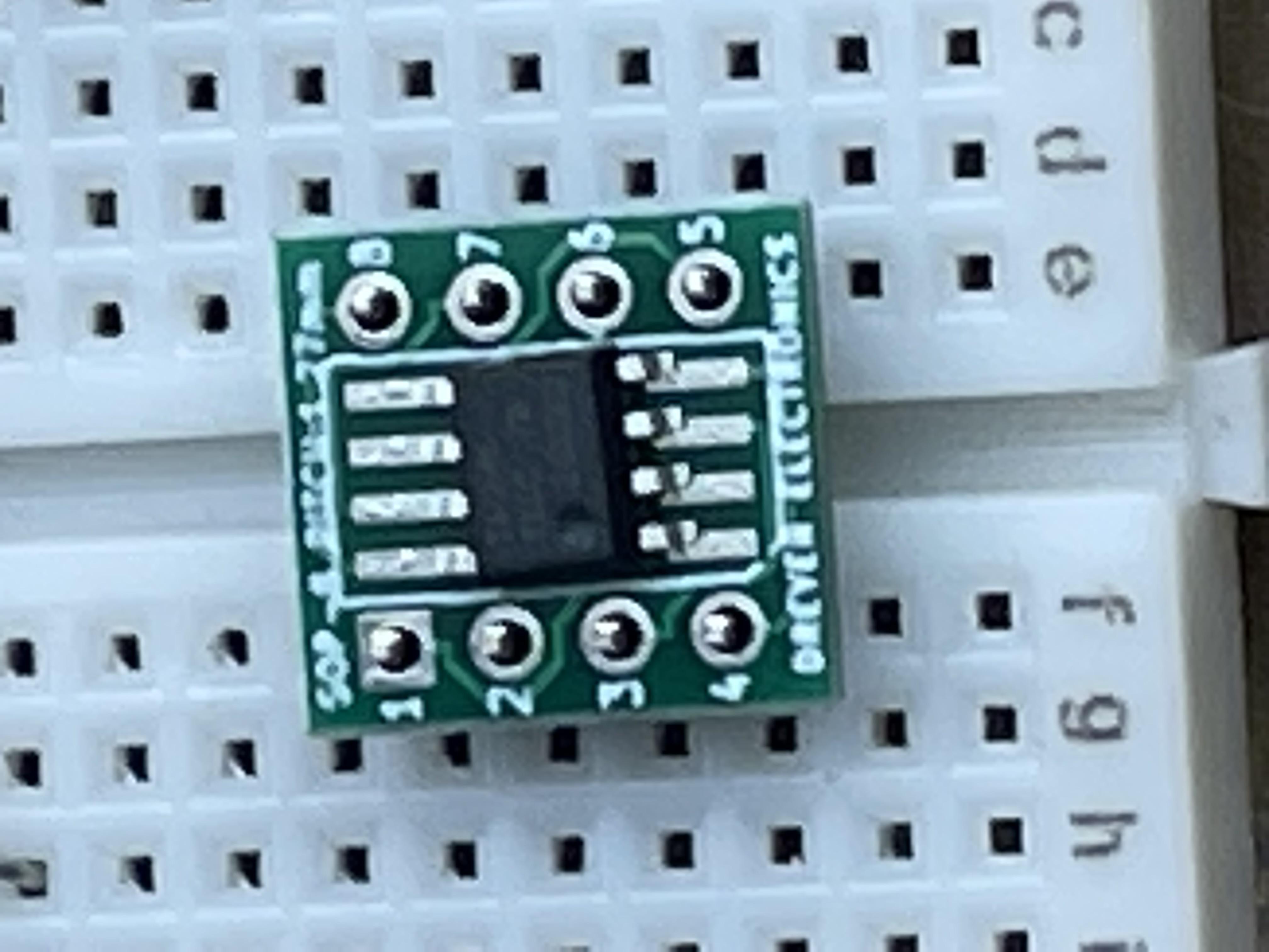
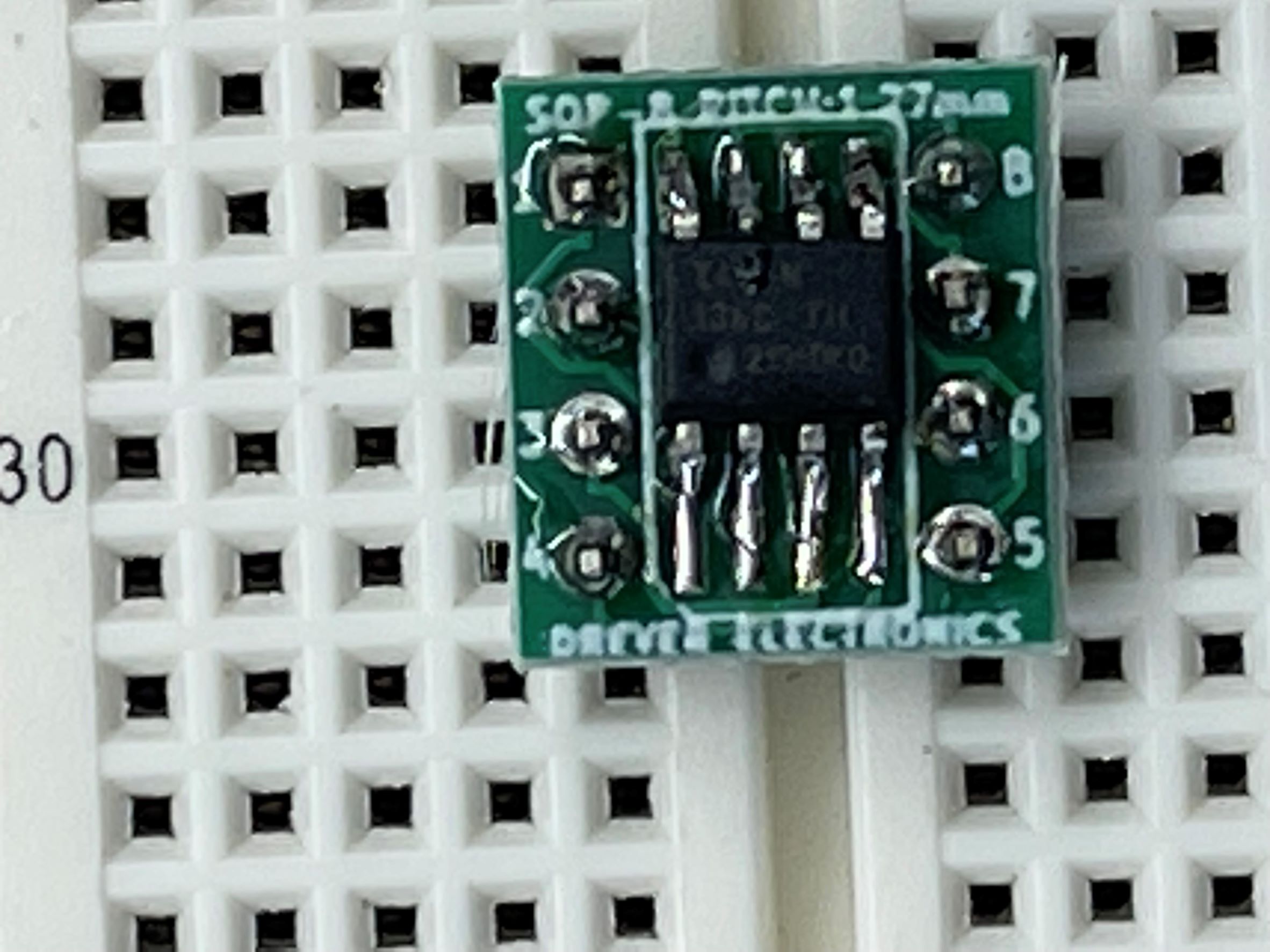
First I started off by breaking off male to male breadboard pins with pliers. We broke them in two sets of 4 prongs. Next I put the pins (short side facing up) into the breadboard horizontal from each other with the DIP Support in-between. I then put the Breakout Board on top of them with the larger metal pads facing upwards for convenience. Next I started to solder the top left and bottom right pins to the chip to make sure it was even on both sides. I also used a fine point tip on my soldering iron because the chip is very small. Next I finished soldering the rest of the pins. Then after the board is all soldered down I put a very small amount of solder on each of the pads that are facing up [I did not have the solder touch the soldering iron tip, I held the tip onto the pad to make it heat up and put the solder onto the pad]. That was less challenging part, next I used a tweezers to hold the very small Attiny412 Chip onto the pads I just put solder on. I put the corner with the small circle dent aligned to pin 4 on the board. I heated up the pad so the chip would just connect to the solder I already put on. I put it on all the corners then added more solder on top to make sure it would connect correctly. After soldering the ATtiny412 chip to the Breakout Board, I kept the chip in the board because we need it to start the programming connections.
For the programming section I used:
-
Two Red Male to Male Wires [Power]
-
Two Black Male to Male Wires [Ground]
-
One Purple Male to Male Wire [UPDI Connection]
-
One Yellow Male to Male Wire [Data Line]
-
One Large Blue LED
-
One Arduino Uno
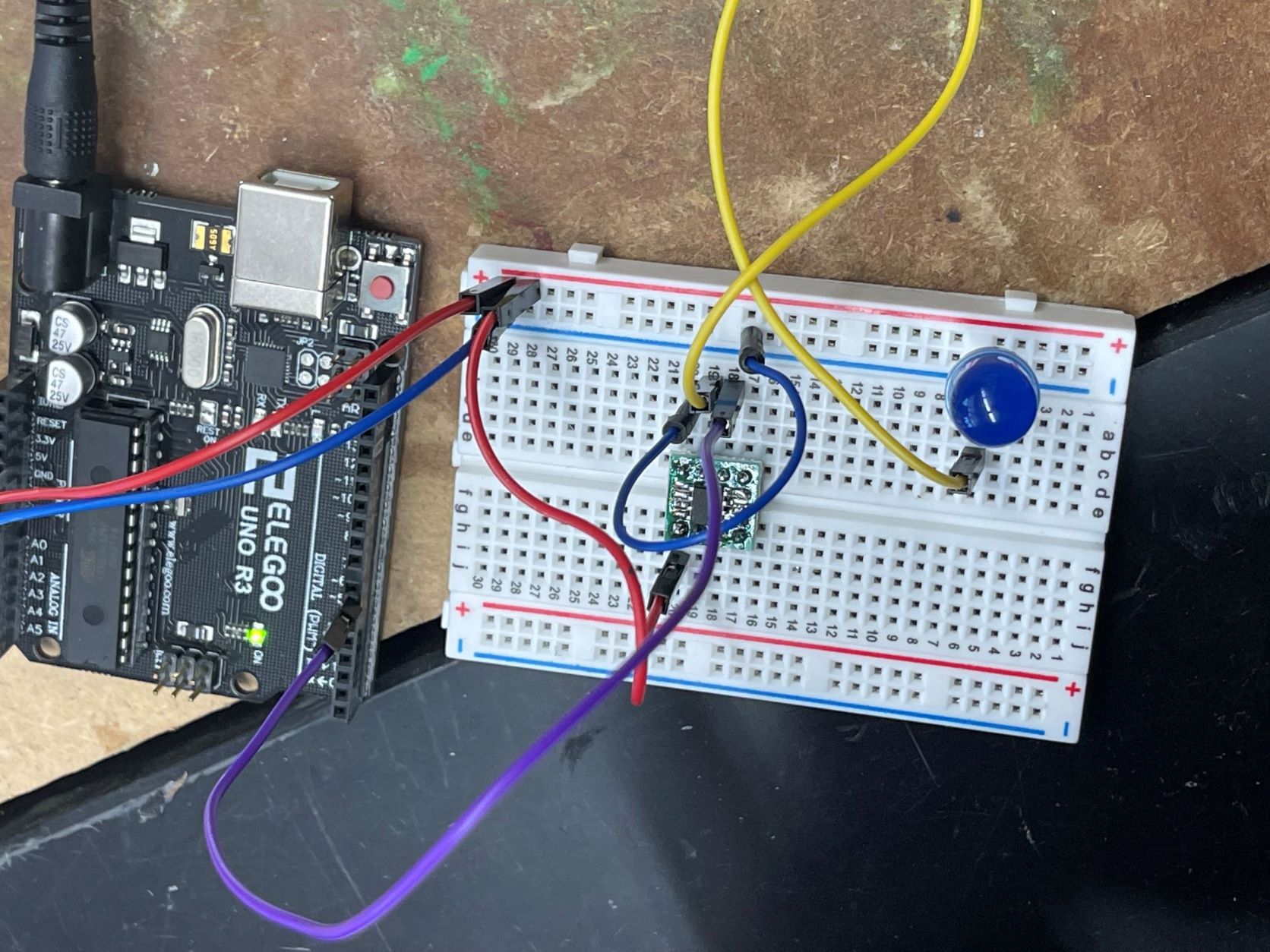
First I started off by looking at the Pin Out sheet for the Attiny412 Chip. Looking at this I see where ground and power is so I connect my first red wire from the power side of the chip to the power [positive] power rail and put the first black wire from the ground side of the chip to the ground (negative) power rail. I then put in my LED . The short pin of the LED goes into the ground (negative) power rail and the long goes into the terminal strip adjacent to that ground pin. Then I used my yellow wire to connect from pin out [4~] (which is aligned with hole 7 on the breakout board as seen on the ATtiny412 pin out sheet) to connect to the long side of my LED [the side in the terminal strip, not the side in the ground power strip]. After I did that I made sure everything was working by loading some used code from my @Tom Dubick. After I knew my Hardware was working it was time to get started on the software.
The software portion I got my Arduino Uno and I used my second red wire to connect the 5V power form the Arduino to the power (positive) power rail. Then I used my other blue wire to connect the Arduino ground (seen as GND) to the breadboards ground (negative) power rail. Lastly I used the purple wire (UPDI Connection) to connect from pin [6~] to the UPDI port on the chip (UPDI port is aligned with hole 6 on the breakout board as seen on Attiny412 pin out sheet). Lastly that is enough wiring and time to start coding.
I connect my Arduino to my computer with a USB type B cable. Then I install Arduino IDE on my windows Laptop. After installing it I go to [File>Preferences] the under the box labeled “Additional Boards Manager URLs:” I paste this link. I then click OK. Next I go to [tools>Board>Boards Managers] and install megaTinyCore board. Next we down load the megaTinyCore file then the jtag2updi Then lastly, I After That I go to [tools>Board>megaTinyCore>ATtiny412] This will set the board to the Attiny412.
Next we used copperboards that were milled and soldered another 412 chip onto it. In total we used:
-
One White LED
-
One 4.99K Resistor
-
One Attiny 412 Chip
-
One 499K Resistor
We looked at the schematic frequently to get the right visual for where and how we were supposed to
Solder the board. At first I soldered the wrong chip onto the board so make sure your 412 chip has a small
Circular indent in it. If it doesn’t then it is the wrong chip. After that we used the same code from above to load
The code onto the new chip from the help of the arduino.