9. Embedded programming
My first step of this week is to mill and solder another SAMD programmer since I was careless and broke the one made week 7. First I used the same file I used and re-milled the board. I then used Barbara Morrows ICE to program my programmer. After re-making my programmer correctly it was time to start this week.

Data Sheet
My first step was to look at the Attiny412 Datasheet. I started to read through and on Page 13 I found this:
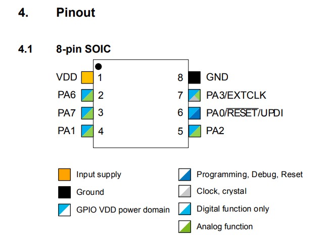
This is the pinout for the attiny412. This was extremely important. I used this to base where I would need to connect everything and have it all connected. I also found this version of the pinout on google:
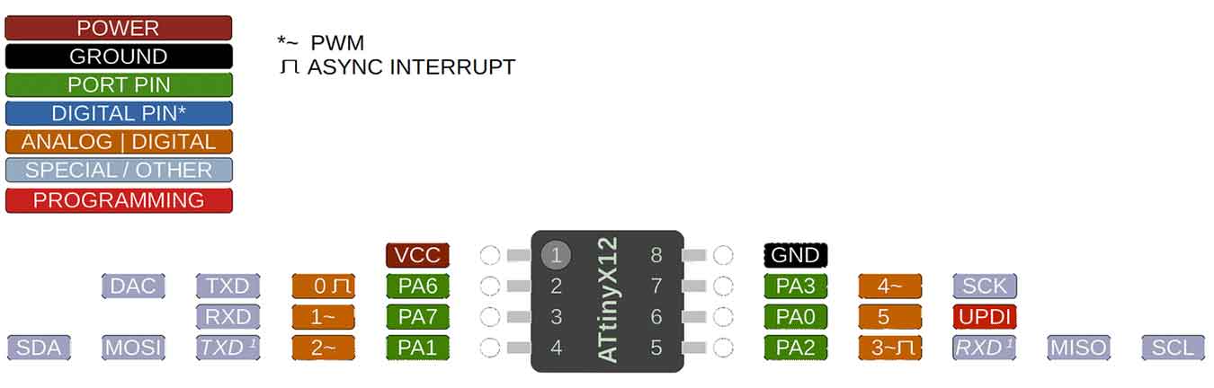
This version was just slightly more informative and easier to read so I prefer this one. Then on page 150 there was a great explanation of the PORT - I/O Pin Configuration. It stated “The I/O pins of the device are controlled by instances of the PORT peripheral registers.” Then goes more in depth. Then I am more of a visual learner so it added this helpful diagram:
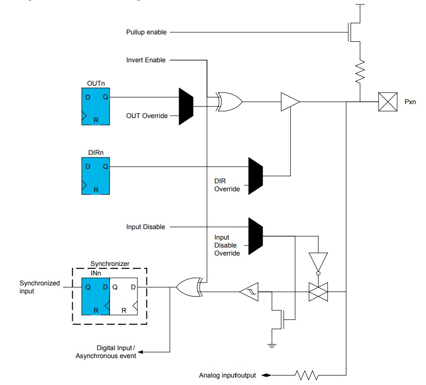
With this information I believe I am able to start the programming piece.
Programming
For this week I am going to be re-using the board I used week 7 during electronics design week. I designed a blinky board with a internal pullup button. Although to go a step up from week 7 and complete this weeks assignment I am going to do the same thing except with Bare Metal Programming. I am going to use binary in Arduino IDE to directly communicate with the memory of the Attiny412.
Bare Metal Programming
What is Bare Metal Programming?
“Bare-metal programming is a term for programming that operates without various layers of abstraction or, as some experts describe it, “without an operating system supporting it.” Bare-metal programming interacts with a system at the hardware level, taking into account the specific build of the hardware.” - Techopedia
My instructors also provided us with this helpful slides that go very in-depth about Bare Metal Programming as a whole.
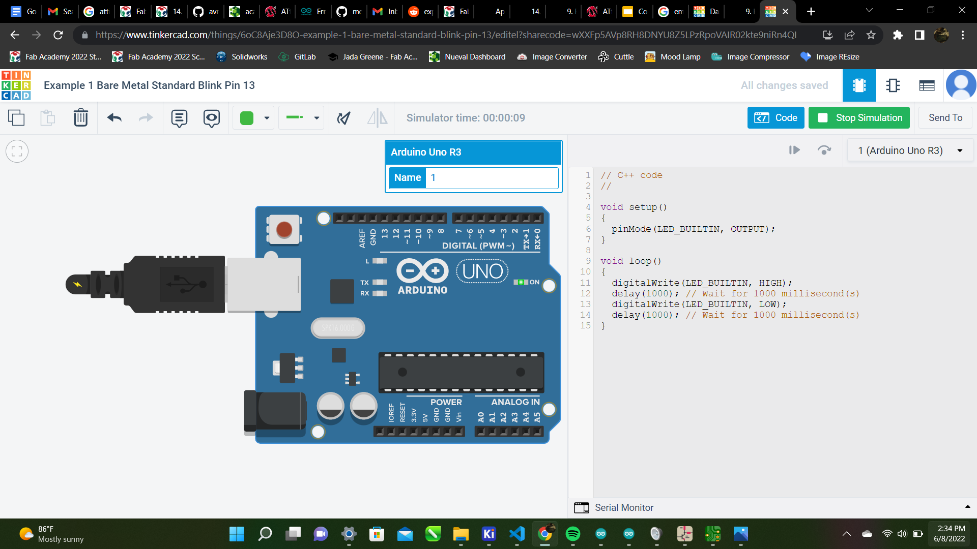
As I read through these slides I followed along through Tinker Circuit. Here I practiced using HIGH and LOW functions:
// C++ code
//

void setup()
{
  pinMode(LED_BUILTIN, OUTPUT);
}

void loop()
{
  digitalWrite(LED_BUILTIN, HIGH);
  delay(1000); // Wait for 1000 millisecond(s)
  digitalWrite(LED_BUILTIN, LOW);
  delay(1000); // Wait for 1000 millisecond(s)
}
This code blinked the built in LED. This was extremely helpful on how to use these functions that were new to me. I then tried it on a physical arduino and it turned out like this:
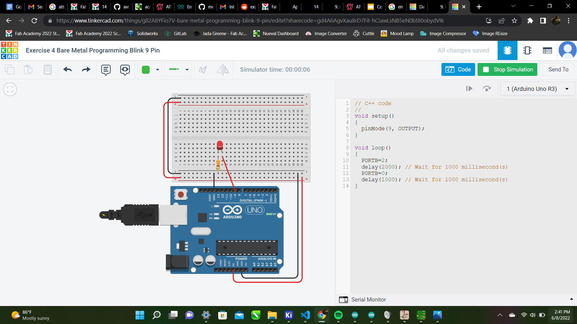
It functioned exactly as it should so I was happy. Next I practiced using the PORT functions. This is where the datasheet was extremely helpful. Here is how it turned out in Tinker Circuit:
// C++ code
//
void setup()
{
  pinMode(9, OUTPUT);
}

void loop()
{
  PORTB=2;
  delay(2000); // Wait for 1000 millisecond(s)
  PORTB=0;
  delay(1000); // Wait for 1000 millisecond(s)
}
This code incorporated a 330 Ohm Resistor and blinked an LED using PORT functions. I again, tried it physically and it worked once again! Here is the video:
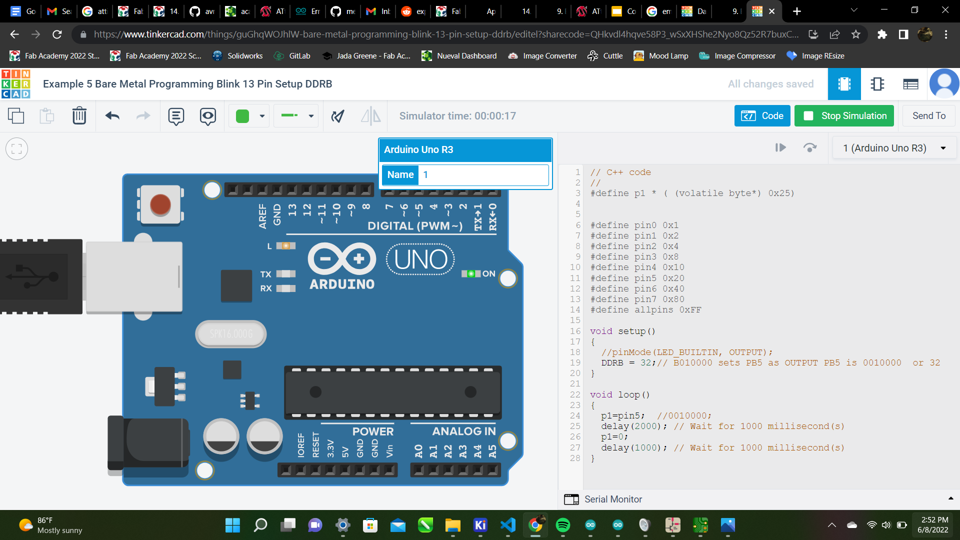
Lastly, I was trying the DDR Register. I again started on tinker circuit and came up with this:
// C++ code
//
#define p1 * ( (volatile byte*) 0x25)


#define pin0 0x1
#define pin1 0x2
#define pin2 0x4
#define pin3 0x8
#define pin4 0x10
#define pin5 0x20
#define pin6 0x40
#define pin7 0x80
#define allpins 0xFF

void setup()
{
  //pinMode(LED_BUILTIN, OUTPUT);
  DDRB = 32;// B010000 sets PB5 as OUTPUT PB5 is 0010000  or 32
}

void loop()
{
  p1=pin5;  //0010000;
  delay(2000); // Wait for 1000 millisecond(s)
  p1=0;
  delay(1000); // Wait for 1000 millisecond(s)
}
This again like the first code blinks the built in LED except using a binary type of code. This was most important because this is the one I will be using in my blinky code later. I tried again physically which worked perfect which was exciting even though I know it will be more complicated when it’s time to do this on my blinky board but this is how it turned out via the arduino:
Three types
The three types I will be trying is Binary, Decimal and Bare Metal. Here are the codes:
Binary
void setup()
{
  pinMode(9, OUTPUT);
}

void loop()
{
  PORTB=B00000010;
  delay(1000);
  PORTB=B00000000;
  delay(1000);
}
Decimal
void setup()
{
  pinMode(9, OUTPUT);
}

void loop()
{
  PORTB=2;
  delay(1000);
  PORTB=0;
  delay(1000);
}
Bare Metal
void setup()
{
  //pinMode(9, OUTPUT);
  DDRB = 9;
}

void loop()
{
  PORTB=2;
  delay(1000);
  PORTB=0;
  delay(1000);
}
I will be using these codes like I did them on the arduino except on my blink board. First I made sure my board was still functional using the Basic Blink Code. This turned out well:
Then I tried the Bare Metal Code from above on it to blink fast:
This worked great! Now I am practicing changing the code values to it will blink slower:
This worked great too!
What I Learned
I learned tons this week. I learned not one but three different types of programming; Decimal, Binary, and Bare Metal. I learned how to apply it to code so it is relevant to what I am doing. The only thing I struggled with was understand all the 1’s and 0’s. Although the Slides were extremely helpful with that. Especially parts like this:
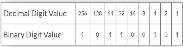
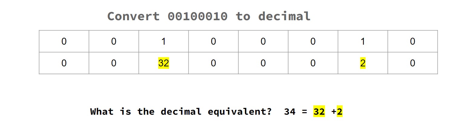
These part of the slides truly saved me a ton of time. And grew my understanding so I was actually understanding what I was doing instead of memorizing.
GroupWork
Aaron, Alaric, Pari, and I worked on using a Jetson NANO to blink an LED. You can see more on that on our group site
Files
I used the same board as from week 7. Here are my Design Files for this week: Files