14. Networking and communications
This week I wanted to connect a main board or a parent board to a child board or node board. I wanted to do this because I am using LED’s a lot for my final project. Also on previous boards I wanted to put power LED’s but I did not know how so hopefully the LED exposure will help me in the future.
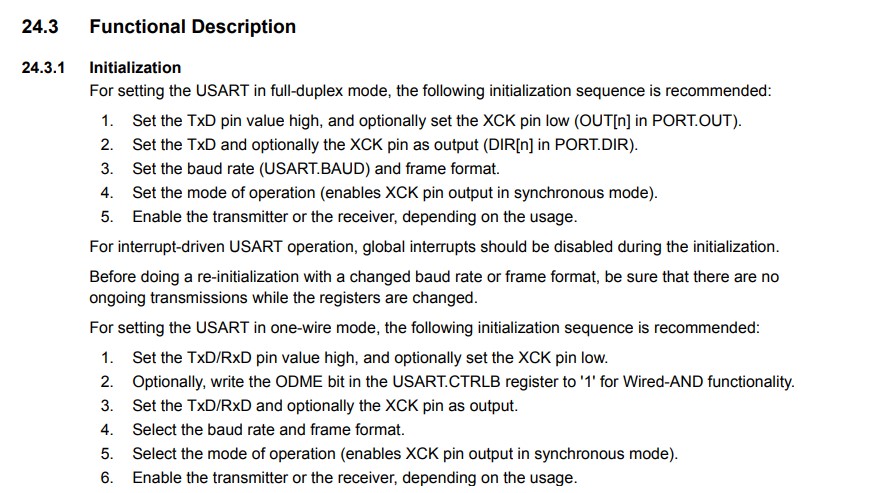
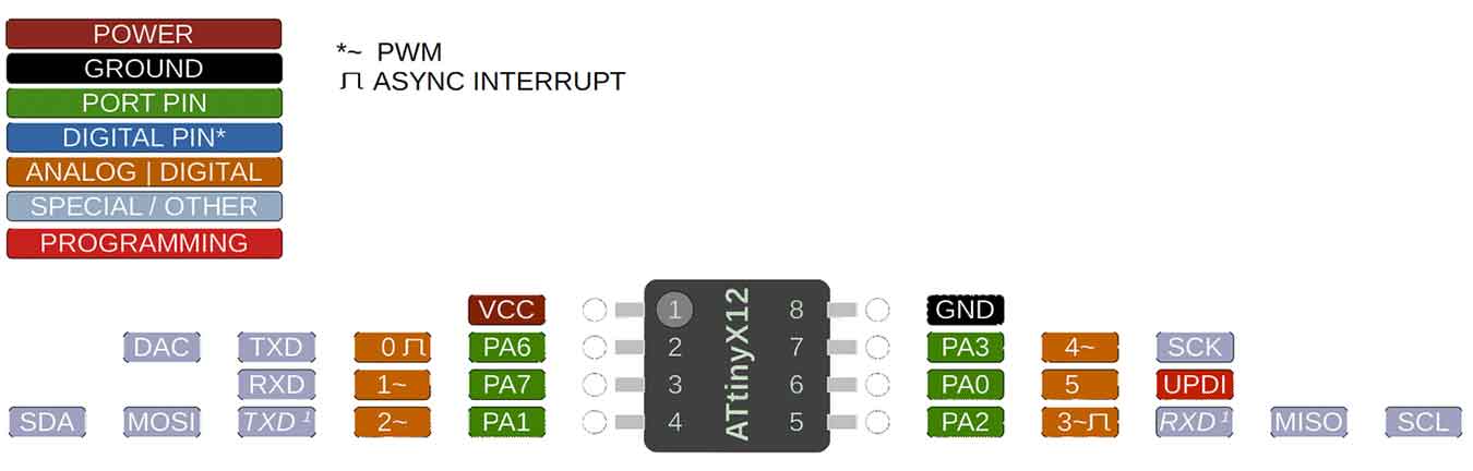
Before I started in KiCAD I went to look in the DataSheet for the Attiny to get more knowledge on how the RX and TX Pins work. So I found on page 248-249 that the Tx was for transmitting data and the Rx was for receiving data.


Then This on page 251 which explained the Port.DIR which I did not understand before and how to do it.
KiCAD
Parent Board
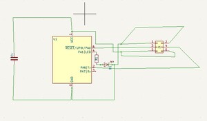
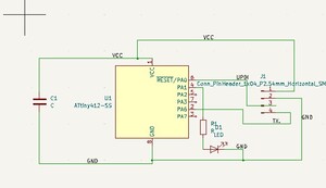
With the information I got from the datasheet I then used this to start on my parent board. I used an:
-
Attiny412
-
330 Ohm Resistor
-
1 uF Capacitor
-
6 Pin Header
-
Blue LED
With these components I made it into this schematic:
Child Board
Next, it was time to start my child board. I added the same components and made sure it had a Tx and Rx pin so it could send and transmit data. The Schematic turned out like this:
Then the board designed looked like this:
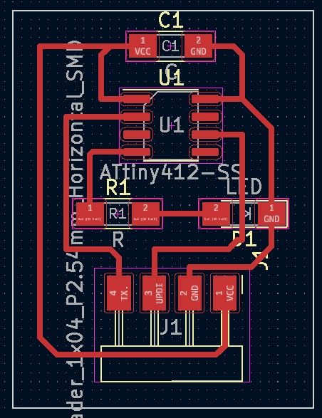
So now it was time to start milling.
Milling/Soldering
I used a 1/64th bit for the traces and a 1/32nd bit for the edge cut. That is so the board will turn out really clean. I milled both and they turned out very nice so I started soldering. I used that material list from above and gathered all the components I needed. I soldered them on pretty quickly and they turned out great. Which means it’s time for my least favorite part; Programming.
Programming
I connected my programmer to my board and it looked good and I wanted to start with uploading a simple blink code to my parent board. I tried that but I got this error saying error uploading to board.

I was extremely confused because this means something is wrong with my board itself. The chip is not receiving the data I am sending out through the programmer. I tried a few more times to upload but then I started to get this error:
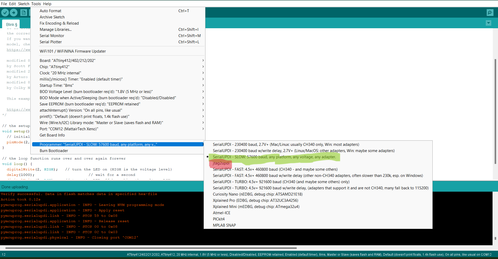
So I realized I blew my ports so I had to restart my computer. I assumed I had a faulty chip so I went to re-mill. I re-milled and got a brand new chip and all components. Then I tried to upload the blink code again and got that same error. I was extremely frustrated so I went back to the drawing board to design a new board entirely. Then I realized I had all the right components and traces correct so that wouldn’t make a difference. I had the pins correct as well so it wasn’t that. I plugged my programmer into an old board to see if that was the problem but it worked perfectly on there it was just my board. So I triple checked if all my connections were right and they were. Then I had my peer look over my code to see if there was something me and all the instructors were missing. He looks at it and realizes that we have it set to the wrong programmer. It is not supposed to be set to “Jtag2UPDI” it is supposed to be set to the other one highlighted in green below.
I was so happy but upset because I wasted a whole day milling new boards because I thought it was physically a problem with my board. So I uploaded this code again and this was the moment of truth:
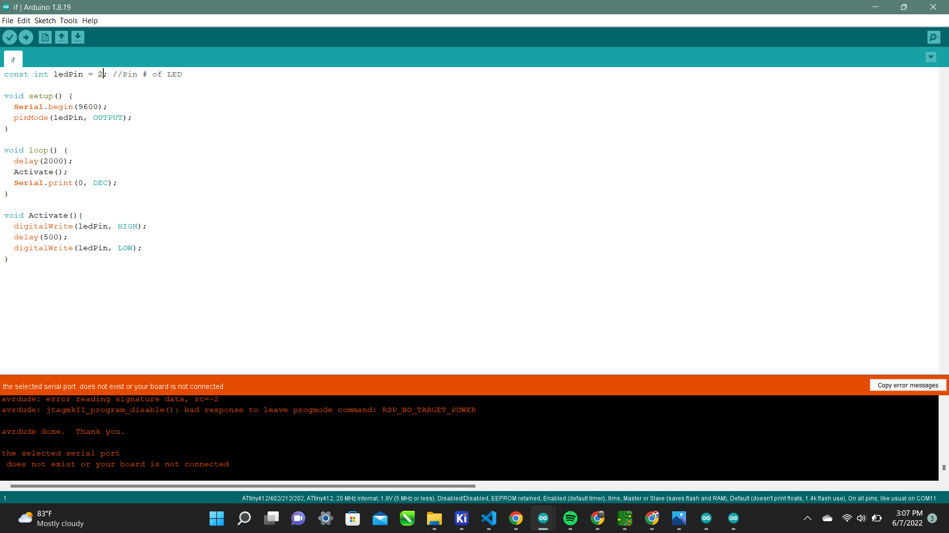
And it worked !! It was an extremely small oversight that cost me hours of extra and unnecessary work. Well Since this worked it is time to upload the main board code to the parent board. I used this code:
const int ledPin = 2; //Pin # of LED

void setup() {
  Serial.begin(9600);
  pinMode(ledPin, OUTPUT);
}

void loop() {
  delay(2000);
  Activate();
  Serial.print(0, DEC);
}

void Activate(){
  digitalWrite(ledPin, HIGH);
  delay(500);
  digitalWrite(ledPin, LOW);
}
Then I uploaded it:
It worked perfectly again! I was ecstatic! But that was only the easy part now it was time to connect both boards and upload the code for the parent and child board. I used this code:
int inByte = 0; //Recieved Byte
const int id = 0; //Local Node ID
const int ledPin = 2; //Pin # of LED

void setup() {
  Serial.begin(9600);
  pinMode(ledPin, OUTPUT);
  Activate();
}

void loop() {
  while (Serial.available()==0);
  int incoming = Serial.parseInt();
  if (incoming == id){
    Activate();
    delay(500);
  }
  else{
    Serial.print(incoming);
  }
}

void Activate(){
  digitalWrite(ledPin, HIGH);
  delay(500);
  digitalWrite(ledPin, LOW);
}
This worked as well!
What I learned
This week was extremely important for me because I could be using this in my final project. I learned how to transmit and recieve data through an Attiny412 which I will be using for my final project. Then I learned the more in depth function of each of the Attiny’s pins.
I now know all the way out to the 3rd columns functions and how I can utilize them.
Groupwork
For this week Nick, Alaric, Jack and I managed to network Arduinos together. You can see more of that on our group site.
Here are my design files