13. Input Week
Sound Sensor
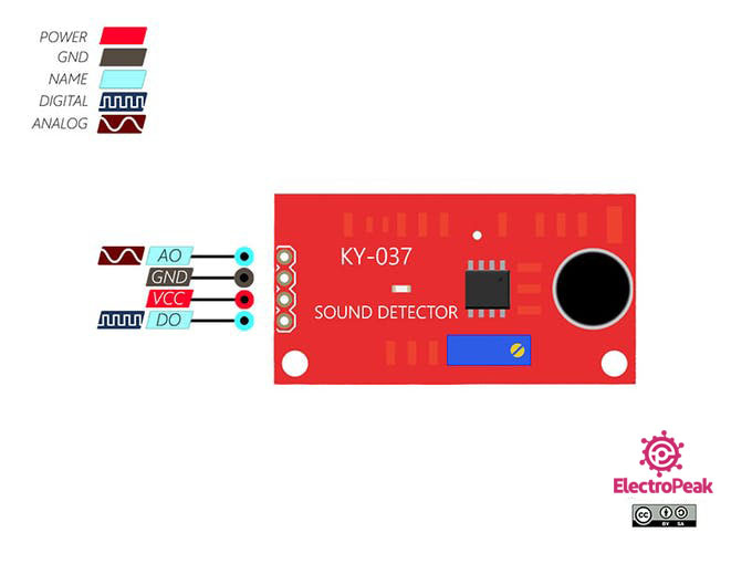
This week I am working with a sound sensor as my input. First, I researched the sensor. After searching online for it I found that it is a KY-037 Sound Sensor. I read more about it here KY-037 module consists of a capacitive microphone and an amplifier circuit. The output of this module is both analog and digital but for my project I will be using analog. The sensor has 4 pins, 2 of them are for power supply.
Pin 1: The analog output. It’s value changes according to the intensity of the received sound. It can be connected to the Arduino analog (ADC) pins.
Pin 4: The digital output. It acts as a key, and it activates when sound intensity has reached a certain threshold. The sensitivity threshold can be adjusted using the potentiometer on the sensor.
This info also aligned with what I read on the datasheet. Here is the pinouts below too:
Design 1
Next, since I did not know much about this sensor physically I wanted to do something really simple. I hooked it up to a breadboard then connected it to a red LED with a 220 Ohm resistor. Then after that was all connected I wrote this extremally simple code for it:
int soundsensor = 3;<br>int led = 7;                // defining pin numbersvoid setup()
{
  pinMode (soundsensor, INPUT);
  pinMode (led, OUTPUT);
}

void loop()
{
  int sensorvalue = digitalRead (soundsensor);            //if the sound intensity is higher than threshold which is set by us,
                                                          //then sensor would return the value as 1
  if (sensorvalue == 1)
  {
    digitalWrite(led, HIGH);
  }

  else
  {
    digitalWrite(led, LOW);
  }

}
I uploaded this to the arduino smoothly and it worked!:
Board
Next it was time to create a board. For this week I wanted it to be heavily involved with my final project so I decided to design a board with not only connections for my sound sensor but also my temperature sensor, switch, FTDI, External Power Supply, and Neopixels. While this might seem like a lot for this week I am focusing solely on the temperature sensor and neopixels to show it is working.
Arduino
I started first on the arduino. I connected the AO pin to A1 on the arduino. The A stands for analog. Then I connected the ground and power to the arduino. I found this video that really helped me with this process. I then used this code from this site:
#include <FastLED.h>

int r=152;
int g=0;
int b=10;

#define LED_PIN     5            //CONNECT DATA PIN OF PIXEL WITH 5 NUMBER PIN OF ARDUINO
#define NUM_LEDS    16           //CHANGE THE VALUE IF YOU WANT TO USE DIFFRENT NUMBER OF LED IN YOUR STRIP,HERE IN MY STRIP NUMBER OF LED IS 60 SO I SET IT 60.

CRGB leds[NUM_LEDS];
CRGB led[NUM_LEDS];

int s=0;

void setup() {

  FastLED.addLeds<WS2812, LED_PIN, GRB>(leds, NUM_LEDS);
  for (int i = NUM_LEDS/2; i >= 0; i--)
  {
     leds[i] = CRGB ( r,g,b);
     leds[NUM_LEDS-i] = CRGB (r,g,b );
     delay(40);
    FastLED.show();
  }
  Serial.begin(9600);
   pinMode(A1,INPUT_PULLUP);

}
void loop()
{
  s=analogRead(A1);
  s=s*2;
  Serial.println(s);
 // delay(50);
  if((s>=450)&&(s<=550))
  {
    leds[(NUM_LEDS/2)-1]=CRGB (0, 0, 255);
    leds[NUM_LEDS/2]=CRGB (0, 0, 255);
  }
  else if((s>=400)&&(s<=450))
  {
    leds[(NUM_LEDS/2)-1]=CRGB (153, 153, 0);
    leds[NUM_LEDS/2]=CRGB (153, 153, 0);
  }
  else if((s>=350)&&(s<=400))
   {
     leds[(NUM_LEDS/2)-1]=CRGB (255, 50, 255);
    leds[NUM_LEDS/2]=CRGB (255, 50, 255);
   }
   else if((s>=300)&&(s<=350))
  {
    leds[(NUM_LEDS/2)-1]=CRGB (10, 25, 217);
    leds[NUM_LEDS/2]=CRGB (10, 25, 217);
  }

    else if((s>=276)&&(s<=300))
   {
     leds[(NUM_LEDS/2)-1]=CRGB (50, 50, 150);
    leds[NUM_LEDS/2]=CRGB (50, 50, 150);
   }
   else if((s>=250)&&(s<=275))
   {
     leds[(NUM_LEDS/2)-1]=CRGB (230, 0, 10);
    leds[NUM_LEDS/2]=CRGB (230, 0, 10);
   }
  else if((s>=235)&&(s<=250))
   {
     leds[(NUM_LEDS/2)-1]=CRGB (0, 160, 0);
    leds[NUM_LEDS/2]=CRGB (0, 160, 0);
   }
   else if((s>=200)&&(s<=230))
   {
     leds[(NUM_LEDS/2)-1]=CRGB (1, 0, 1);
    leds[NUM_LEDS/2]=CRGB (1, 0, 1);
   }
  else
  {
     leds[(NUM_LEDS/2)-1] = CRGB ( r,s-100,b);
     leds[NUM_LEDS/2] = CRGB ( r,s-100,b);
  }
    for (int i = 0; i <= ((NUM_LEDS/2)-2); i++)
  {
     leds[i] = leds[i+1];
     leds[NUM_LEDS-1-i] = leds[(NUM_LEDS)-i-2];

  }
 FastLED.show();
 delay(25);

}
This code has a mirror function but that is only true if there is an odd amount of LED’s. With an even number the Lights will just react through the whole strip which is what I wanted so I have my number of LED’s set to 16. I have my LED’s connected to a 5V 5A power supply. This is perfect because it will be enough power to run both of my sensors when I put them together.
KiCAD
It was time to design a board for this code. I chose to use an Attiny1614 as my processor due to the size of the memory it had. Here is the schematic I designed. This includes everything for my final project as I said above but I am only working w the sound sensor and neopixels for now.

Here is how the board turned out:

I struggled a lot with board design. I didn’t want to but I had to add numerous 0 Ohm resistors. I didn’t know if it was because I had a lot of components or if I designed it poorly but it took me a long time to get it to this. Next, it was time to mill it out.
I milled this pretty quickly and got it all soldered. Now it was time for the hard part…
Code
I used the code from the sound sensor and changed it to the tinyNeoPixel library. I had to change it because the Attiny1614 does NOT recognize libraries like Adafruit_NeoPixel and FastLED as libraries. So I had to go through and change it all to tinyNeoPixel. This was a little tough to do because I kept getting syntax errors but from all the coding I have been doing recently I knew generally how to resolve those. Also here on the tinyNeoPixel creators git page he explains that, “Adafruit one to be readily understood, simple, with one purpose that it handles capably, and extensively commented, especially the assembly.” So he based the tinyNeopixel library off of the Adafruit_NeoPixel library which is probably why is was easier to modify. Then after hacking down on all the errors I finally got the code to verify! This is the code:
//#include <Adafruit_NeoPixel.h>
#include <tinyNeoPixel.h>
//#define NUMLEDS 100


#define N_PIXELS  5  // Number of pixels you are using
#define MIC_PIN   9  // Microphone is attached to Trinket GPIO #2/Gemma D2 (A1)
#define LED_PIN    0  // NeoPixel LED strand is connected to GPIO #0 / D0
#define DC_OFFSET  0  // DC offset in mic signal - if unusure, leave 0
#define NOISE     100  // Noise/hum/interference in mic signal
#define SAMPLES   5  // Length of buffer for dynamic level adjustment
#define TOP       (N_PIXELS +1) // Allow dot to go slightly off scale
// Comment out the next line if you do not want brightness control or have a Gemma
#define POT_PIN    3  // if defined, a potentiometer is on GPIO #3 (A3, Trinket only)


byte
  peak      = 0,      // Used for falling dot
  dotCount  = 0,      // Frame counter for delaying dot-falling speed
  volCount  = 0;      // Frame counter for storing past volume data

int
  vol[SAMPLES],       // Collection of prior volume samples
  lvl       = 10,     // Current "dampened" audio level
  minLvlAvg = 0,      // For dynamic adjustment of graph low & high
  maxLvlAvg = 512;

tinyNeoPixel strip = tinyNeoPixel(N_PIXELS, LED_PIN, NEO_GRB);
//Adafruit_NeoPixel  strip = Adafruit_NeoPixel(N_PIXELS, LED_PIN, NEO_GRB + NEO_KHZ800);

void setup() {
  //memset(vol, 0, sizeof(vol));
  memset(vol,0,sizeof(int)*SAMPLES);//Thanks Neil!
  strip.begin();
}
void loop() {
  uint8_t  i;
  uint16_t minLvl, maxLvl;
  int      n, height;
  n   = analogRead(MIC_PIN);                 // Raw reading from mic
  n   = abs(n - 512 - DC_OFFSET);            // Center on zero
  n   = (n <= NOISE) ? 0 : (n - NOISE);      // Remove noise/hum
  lvl = ((lvl * 7) + n) >> 3;    // "Dampened" reading (else looks twitchy)

  // Calculate bar height based on dynamic min/max levels (fixed point):
  height = TOP * (lvl - minLvlAvg) / (long)(maxLvlAvg - minLvlAvg);

  if(height < 0L)       height = 0;      // Clip output
  else if(height > TOP) height = TOP;
  if(height > peak)     peak   = height; // Keep 'peak' dot at top

// if POT_PIN is defined, we have a potentiometer on GPIO #3 on a Trinket
//    (Gemma doesn't have this pin)
  uint8_t bright = 255;
#ifdef POT_PIN
   bright = analogRead(POT_PIN);  // Read pin (0-255) (adjust potentiometer
                                  //   to give 0 to Vcc volts
#endif
  strip.setBrightness(bright);    // Set LED brightness (if POT_PIN at top
                                  //  define commented out, will be full)
  // Color pixels based on rainbow gradient
  for(i=0; i<N_PIXELS; i++) {
    if(i >= height)
       strip.setPixelColor(i,   0,   0, 0);
    else
       strip.setPixelColor(i,Wheel(map(i,0,strip.numPixels()-1,30,150)));
    }

   strip.show(); // Update strip

  vol[volCount] = n;                      // Save sample for dynamic leveling
  if(++volCount >= SAMPLES) volCount = 0; // Advance/rollover sample counter

  // Get volume range of prior frames
  minLvl = maxLvl = vol[0];
  for(i=1; i<SAMPLES; i++) {
    if(vol[i] < minLvl)      minLvl = vol[i];
    else if(vol[i] > maxLvl) maxLvl = vol[i];
  }
  // minLvl and maxLvl indicate the volume range over prior frames, used
  // for vertically scaling the output graph (so it looks interesting
  // regardless of volume level).  If they're too close together though
  // (e.g. at very low volume levels) the graph becomes super coarse
  // and 'jumpy'...so keep some minimum distance between them (this
  // also lets the graph go to zero when no sound is playing):
  if((maxLvl - minLvl) < TOP) maxLvl = minLvl + TOP;
  minLvlAvg = (minLvlAvg * 63 + minLvl) >> 6; // Dampen min/max levels
  maxLvlAvg = (maxLvlAvg * 63 + maxLvl) >> 6; // (fake rolling average)
}

// Input a value 0 to 255 to get a color value.
// The colors are a transition r - g - b - back to r.
uint32_t Wheel(byte WheelPos) {
  if(WheelPos < 85) {
   return strip.Color(WheelPos * 3, 255 - WheelPos * 3, 0);
  } else if(WheelPos < 170) {
   WheelPos -= 85;
   return strip.Color(255 - WheelPos * 3, 0, WheelPos * 3);
  } else {
   WheelPos -= 170;
   return strip.Color(0, WheelPos * 3, 255 - WheelPos * 3);
  }
}
And now it was time to plug it in. I was extremely nervous because I wasn’t sure if it was going to work. So I plugged it and here was the result:
It worked!! I was extremely happy because I’ve been having a lot of losses and problems with my codes recently this was the win I needed to help keep me motivated. After this worked I was feeling lucky so I went back to my main code. I again got a better understanding by reading through the tinyNeoPixel libraries git page and also comparing my code to the example codes from the tinyNeoPixel library to help me modify mine. After hours of doing that I finally got it to compile with no errors.
Groupwork
For this week Pari, Andrew and I worked on reading Pari’s Doppler Radar sensor. You can read more of that on our group site
#### Design Files