5. Electronics production
ATTiny Chip
We started Fab Academy off with soldering ATtiny412 chips onto these Breakout Boards. We used :
-
Soldering Iron (750℉) (Fine Point Soldering Tip)
-
0.80mm Solder
-
ATtiny412 Chip
-
Breakout Board (PCB Board)
-
Pliers
-
Tweezers
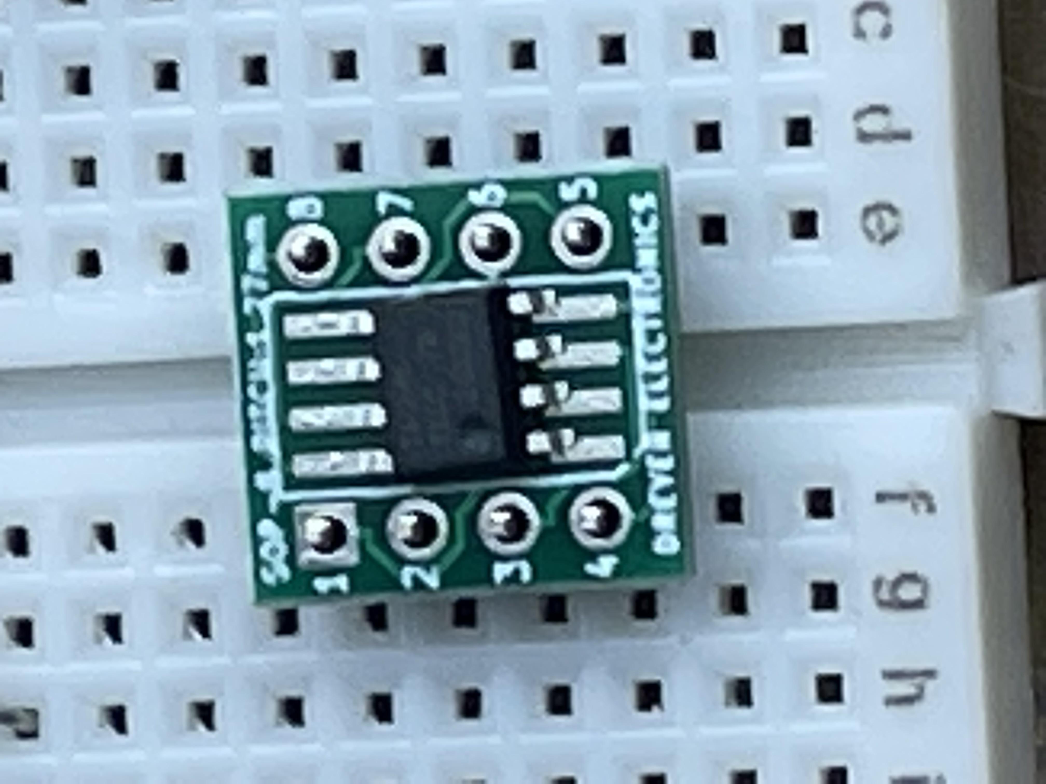
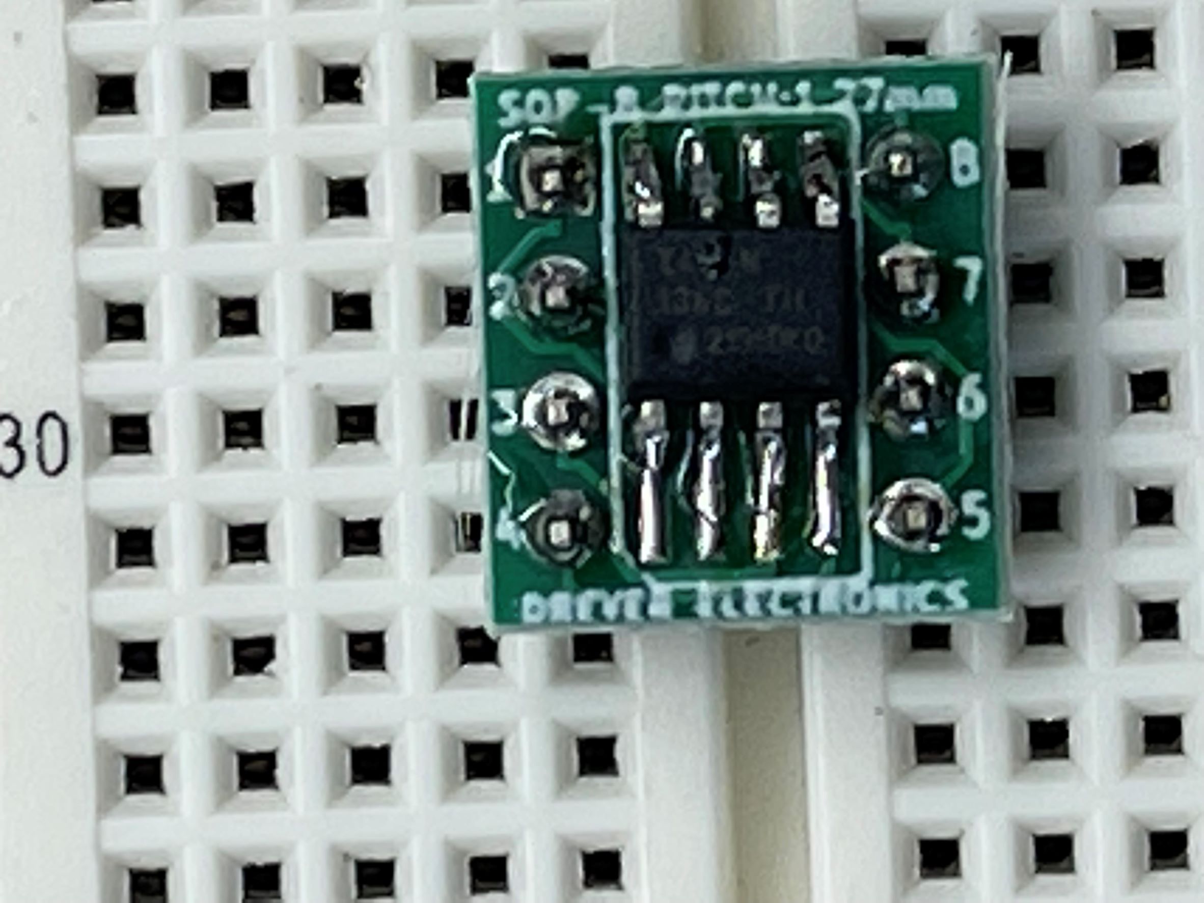
First I started off by breaking off male to male breadboard pins with pliers. We broke them in two sets of 4 prongs. Next I put the pins (short side facing up) into the breadboard horizontal from each other with the DIP Support in-between. I then put the Breakout Board on top of them with the larger metal pads facing upwards for convenience. Next I started to solder the top left and bottom right pins to the chip to make sure it was even on both sides. I also used a fine point tip on my soldering iron because the chip is very small. Next I finished soldering the rest of the pins. Then after the board is all soldered down I put a very small amount of solder on each of the pads that are facing up [I did not have the solder touch the soldering iron tip, I held the tip onto the pad to make it heat up and put the solder onto the pad]. That was less challenging part, next I used a tweezers to hold the very small Attiny412 Chip onto the pads I just put solder on. I put the corner with the small circle dent aligned to pin 4 on the board. I heated up the pad so the chip would just connect to the solder I already put on. I put it on all the corners then added more solder on top to make sure it would connect correctly. After soldering the ATtiny412 chip to the Breakout Board, I kept the chip in the board because we need it to start the programming connections.
For the programming section I used:
-
Two Red Male to Male Wires [Power]
-
Two Black Male to Male Wires [Ground]
-
One Purple Male to Male Wire [UPDI Connection]
-
One Yellow Male to Male Wire [Data Line]
-
One Large Blue LED
-
One Arduino Uno
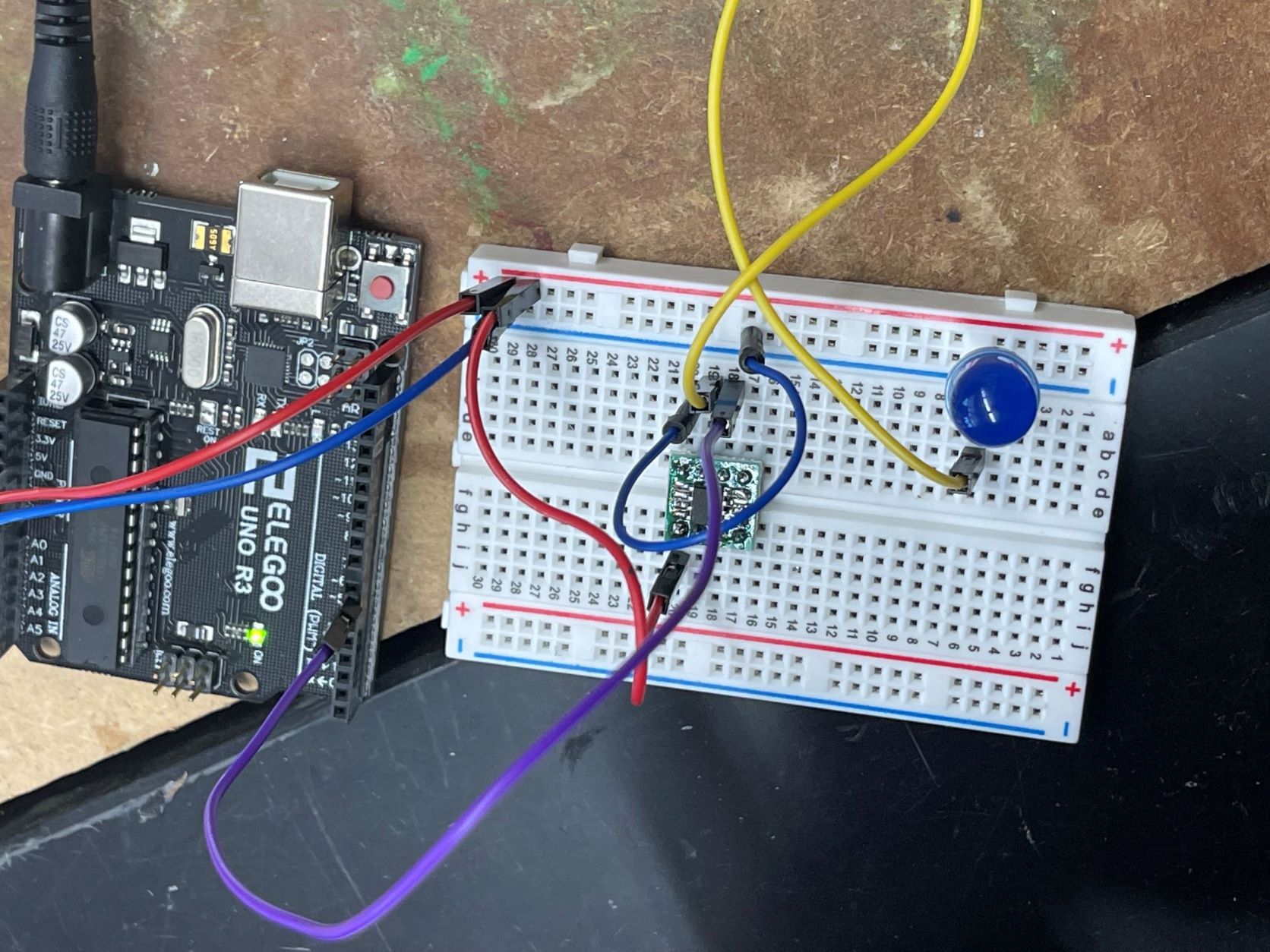
First I started off by looking at the Pin Out sheet for the Attiny412 Chip. Looking at this I see where ground and power is so I connect my first red wire from the power side of the chip to the power [positive] power rail and put the first black wire from the ground side of the chip to the ground (negative) power rail. I then put in my LED . The short pin of the LED goes into the ground (negative) power rail and the long goes into the terminal strip adjacent to that ground pin. Then I used my yellow wire to connect from pin out [4~] (which is aligned with hole 7 on the breakout board as seen on the ATtiny412 pin out sheet) to connect to the long side of my LED [the side in the terminal strip, not the side in the ground power strip]. After I did that I made sure everything was working by loading some used code from my @Tom Dubick. After I knew my Hardware was working it was time to get started on the software.
The software portion I got my Arduino Uno and I used my second red wire to connect the 5V power form the Arduino to the power (positive) power rail. Then I used my other blue wire to connect the Arduino ground (seen as GND) to the breadboards ground (negative) power rail. Lastly I used the purple wire (UPDI Connection) to connect from pin [6~] to the UPDI port on the chip (UPDI port is aligned with hole 6 on the breakout board as seen on Attiny412 pin out sheet). Lastly that is enough wiring and time to start coding.
I connect my Arduino to my computer with a USB type B cable. Then I install Arduino IDE on my windows Laptop. After installing it I go to [File>Preferences] the under the box labeled “Additional Boards Manager URLs:” I paste this link. I then click OK. Next I go to [tools>Board>Boards Managers] and install megaTinyCore board. Next we down load the megaTinyCore file then the jtag2updi Then lastly, I After That I go to [tools>Board>megaTinyCore>ATtiny412] This will set the board to the Attiny412.
Next we used copperboards that were milled and soldered another 412 chip onto it. In total we used:
-
One White LED
-
One 4.99K Resistor
-
One Attiny 412 Chip
-
One 499K Resistor
We looked at the schematic frequently to get the right visual for where and how we were supposed to
Solder the board. At first I soldered the wrong chip onto the board so make sure your 412 chip has a small
Circular indent in it. If it doesn’t then it is the wrong chip. After that we used the same code from above to load
The code onto the new chip from the help of the arduino.
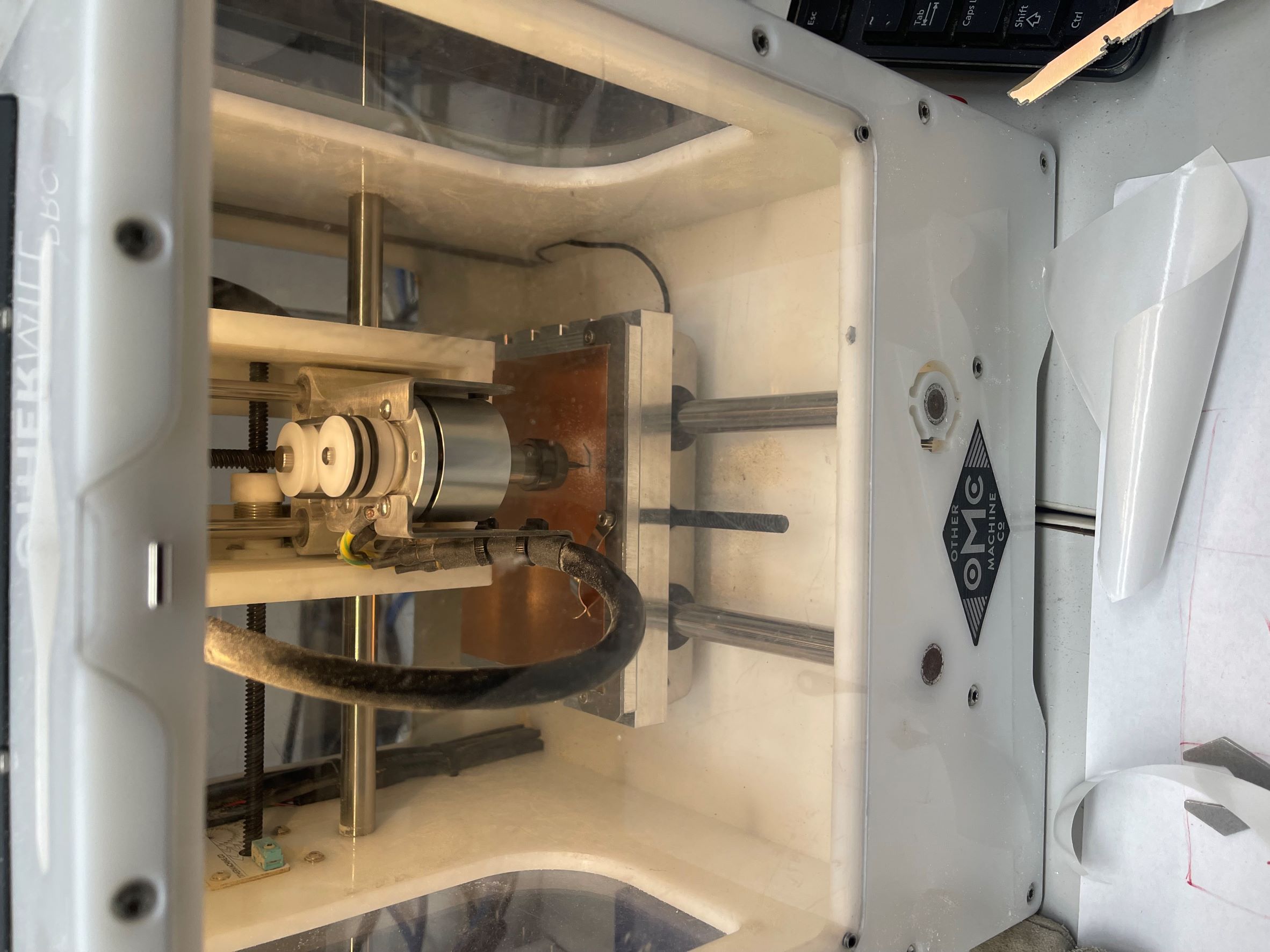
Board Milling
I started off milling by looking over tbe milling machine workflow provided by my instructor Tom Dubick. I reccomend reading the workflow even before starting rather than going through it as you work is that there could be things that you wish you would’ve seen before you did something else first. It’s better to get all the knowledge about the machine prior to starting. So after I read the workflow I went to our fab academy google classroom and downloaded the file I needed for the board.
After I downloaded the file I realized there was still old copper from the miller before me on the machine so I got a spatula tool and pryed up the old copper with a glove on to start new. Always use a glove when doing steps where your hand is close to the copper shards because you can get very hurt without one.
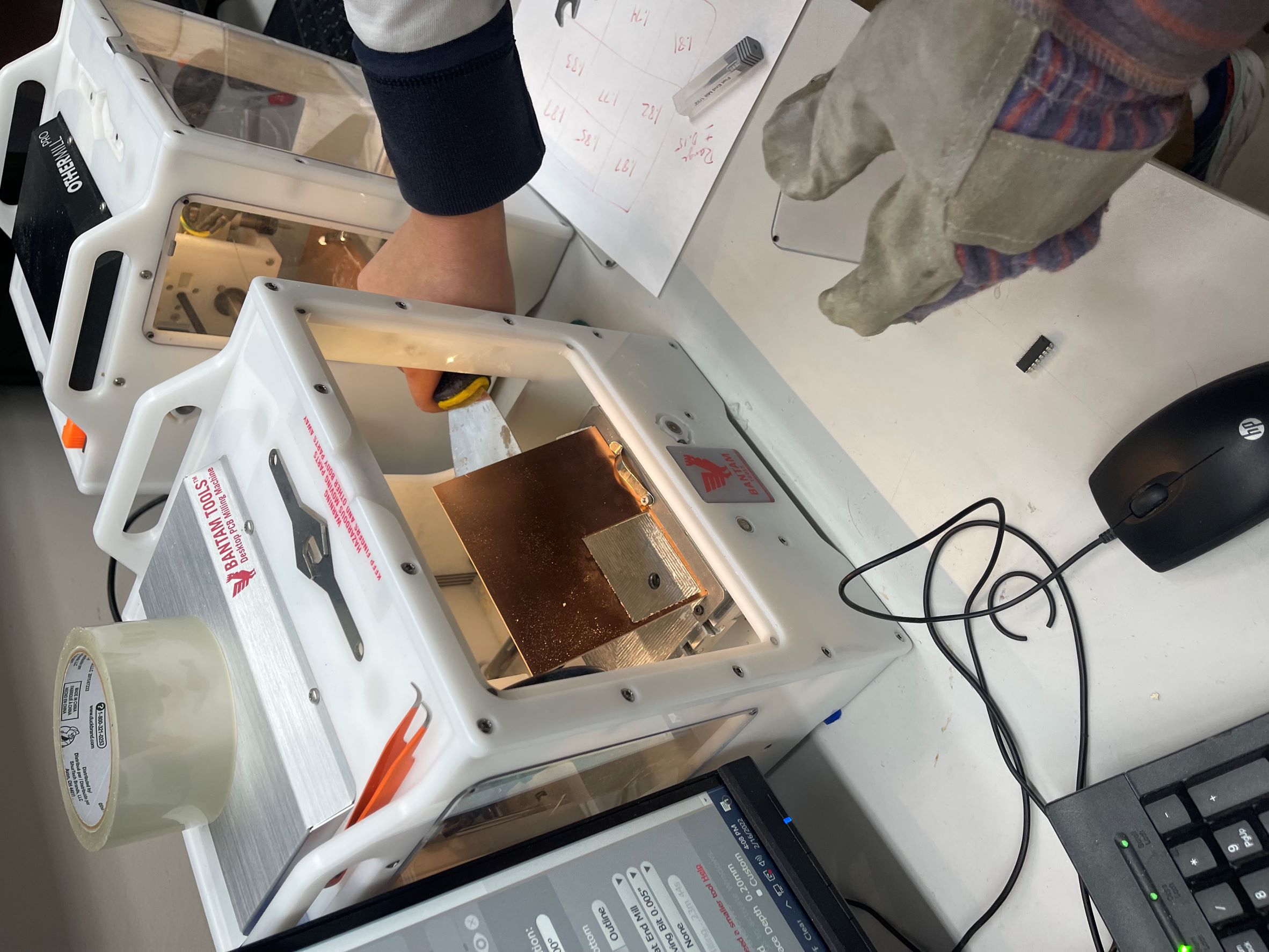
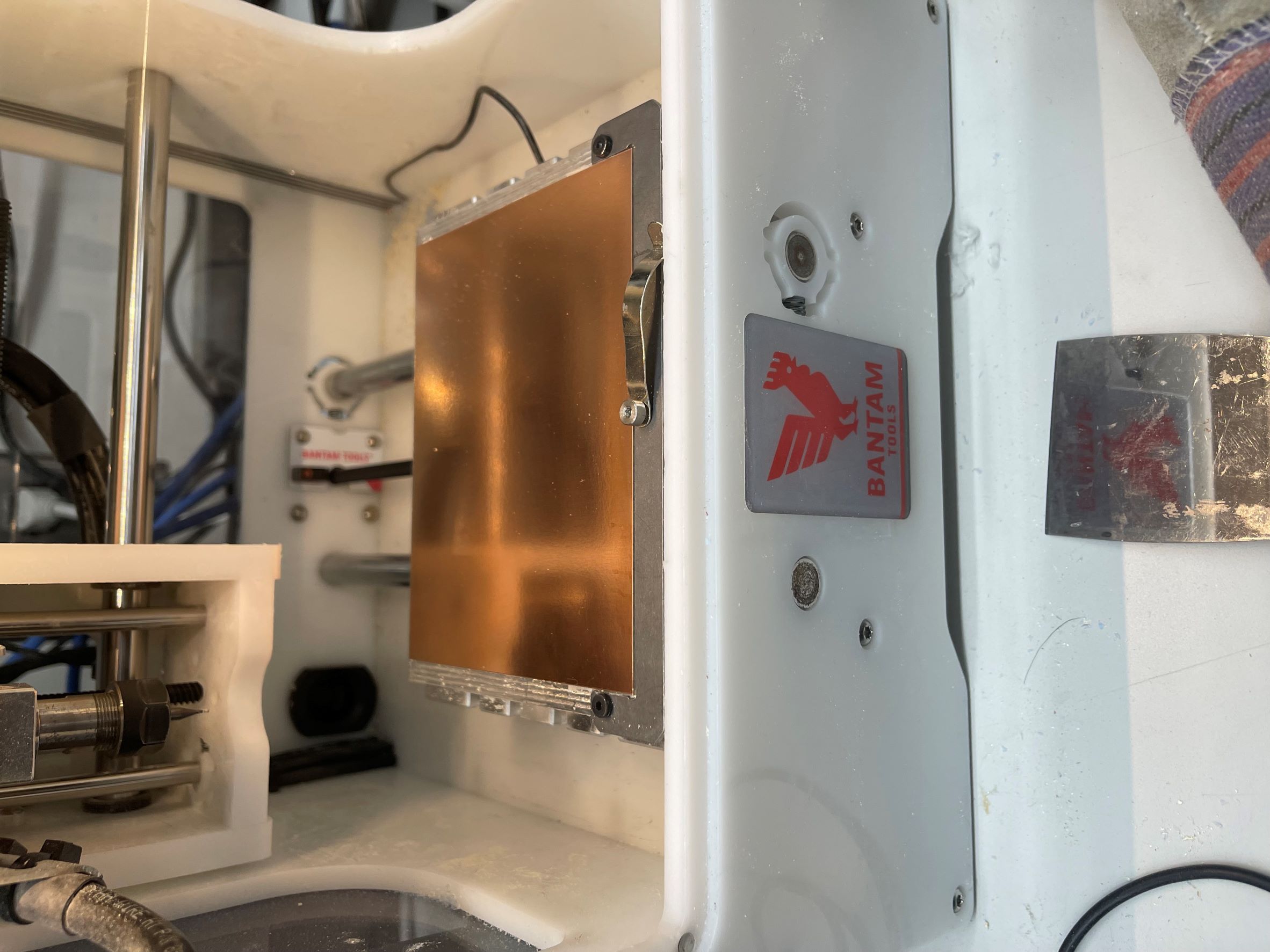
I then started to vacuum out excess copper dust so I had a completely clean slate to work. I got a new peice of copper and used strips of nitto tape to cover the entire back and then used a green tool to press it flush onto the milling machine with no air bubbles. After I assured it was firm to the bed I wiped down the copper with rubbing alcohol.
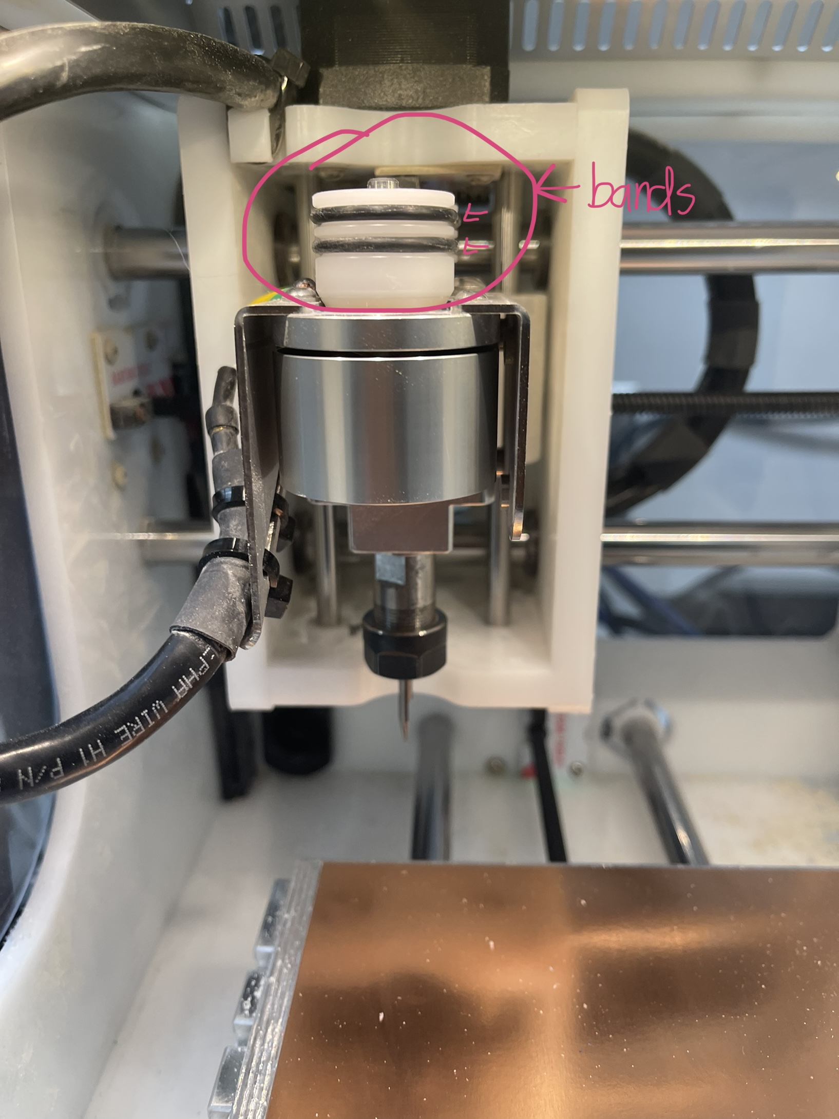
Next I opened the file I downloaded from google classroom into the Bantam Tools software. I added in the 1/32 flat end mill bit and the PCB Engraving Bit 0.005” into the software. I then realized that one of the milling bands that spins the bit snapped and there was one that was not in good shape left. If that one broke too it would stop our cut so I removed the bad looking band and replaced it with two brand new ones.
After that I did not change the trace clearence and trace depth to 0.25mm initially. After making sure everything was correct I founf the 0.005” PCB Engraving Bit then I located the tool to start engraving. Then I attatched the metal clip onto the board because thats how the board eletronically connects to the machine. After that I clicked “Bit Breaker” at the top then went to “Probe Material Thickness”. I moved the bit to around the point of where I would be milling on the board so I could get the most accurate measurement.
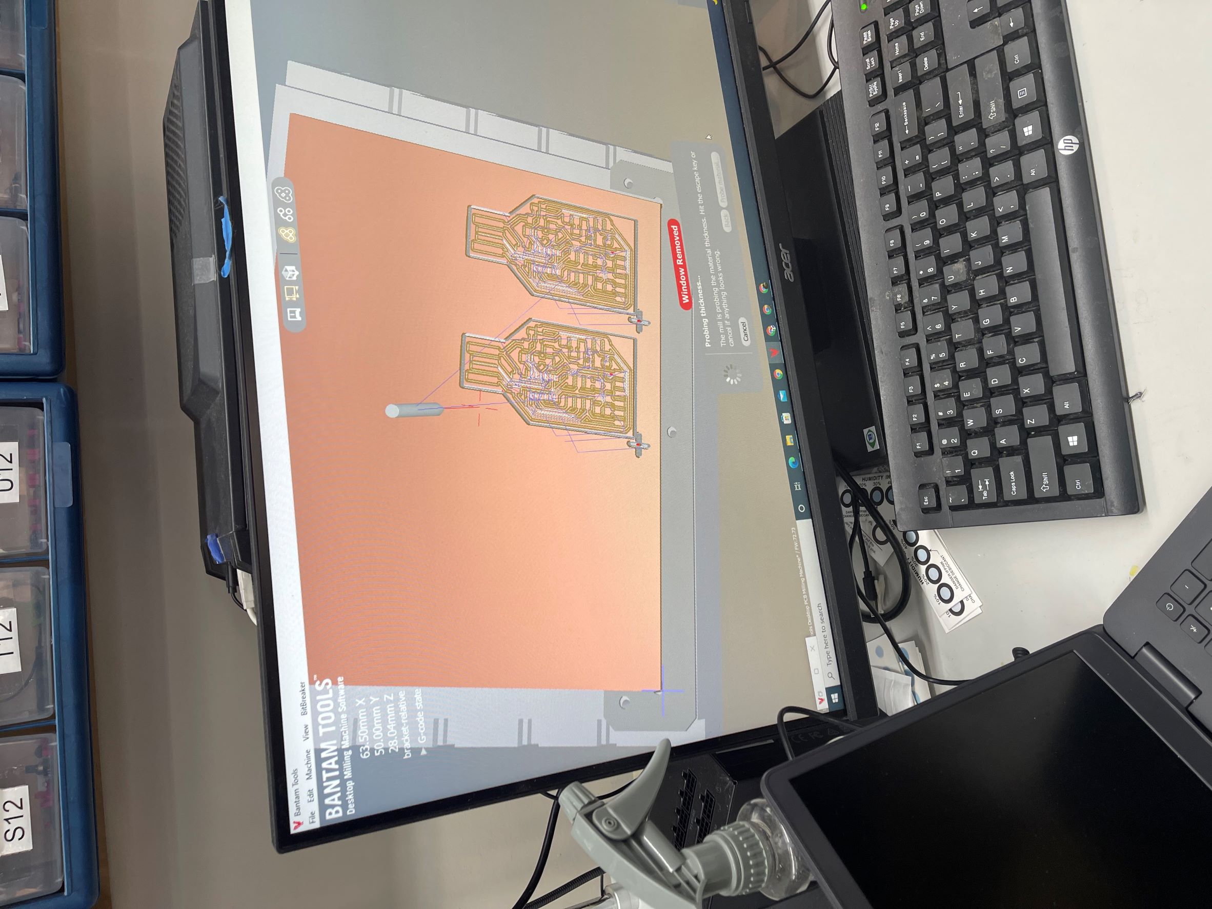
After I triple checked everything I started the cut. It started to cut nicely but then I realized that the outline of the board did not look correct.
It was rectangular when it was supposed to be the shape of a usb plug. So I stopped the cut and realized that it was the file I downloaded that was wrong. I should have gone directly to Mr. Hariss’s Site and downloaded the file directly from his git because the previous file from the google classroom did not have the correct outline. So after I downloaded the correct file I restarted this milling process on a new machine because the previous machine was the slowest machine and was going to take almost 45 minutes per board. This next cut worked out perfectly so I used the glove again to remove the board from the bed with the spatula tool. I removed the tape from the underside of the board and the excess copper. Then I sanded down the edges of the board with the glove and banged it gently against the table to get off any excess copper dust. Then I finished by vacuuming the inside of the bantam machine and cleaning my workspace and putting the bits back.
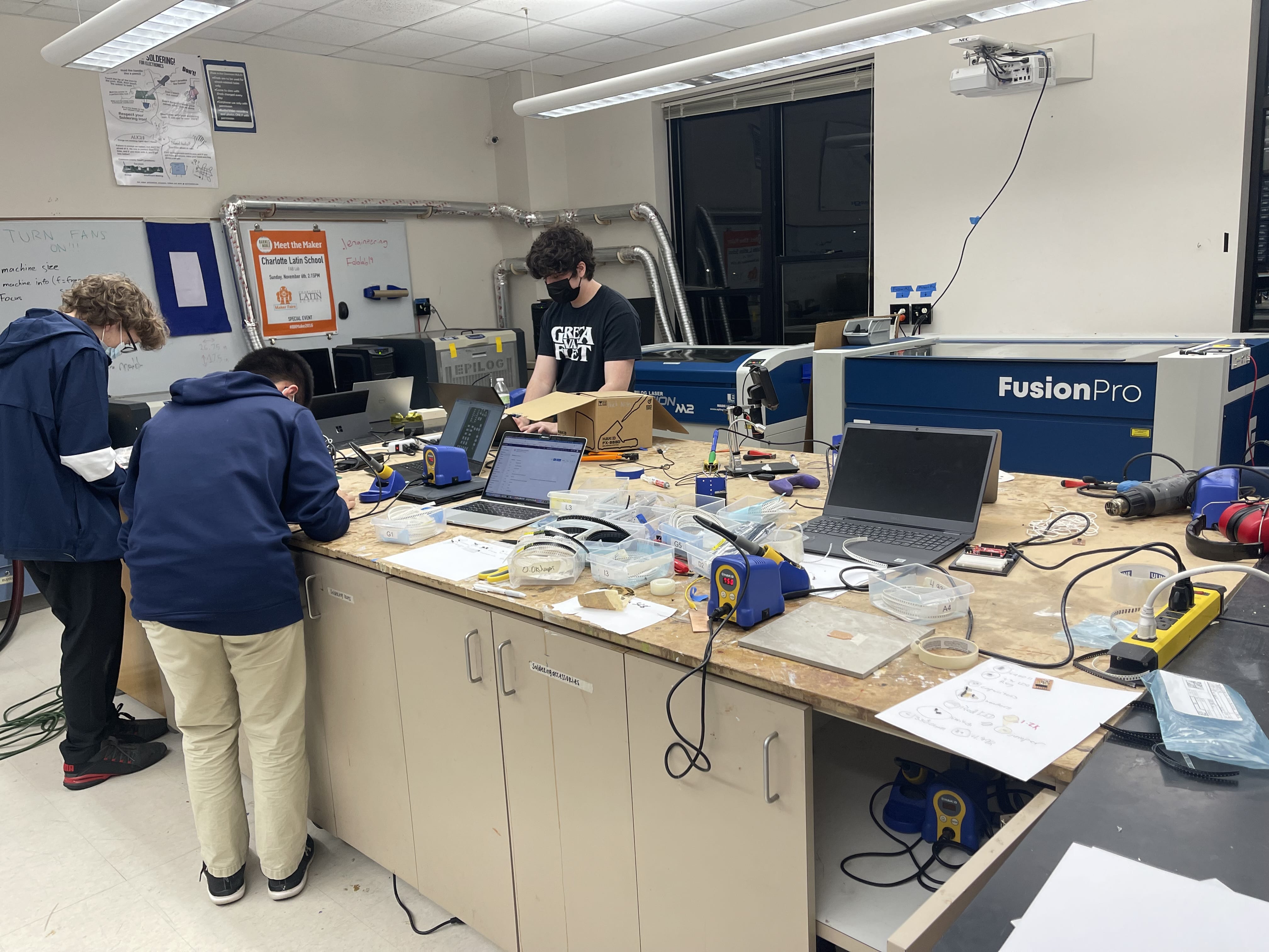
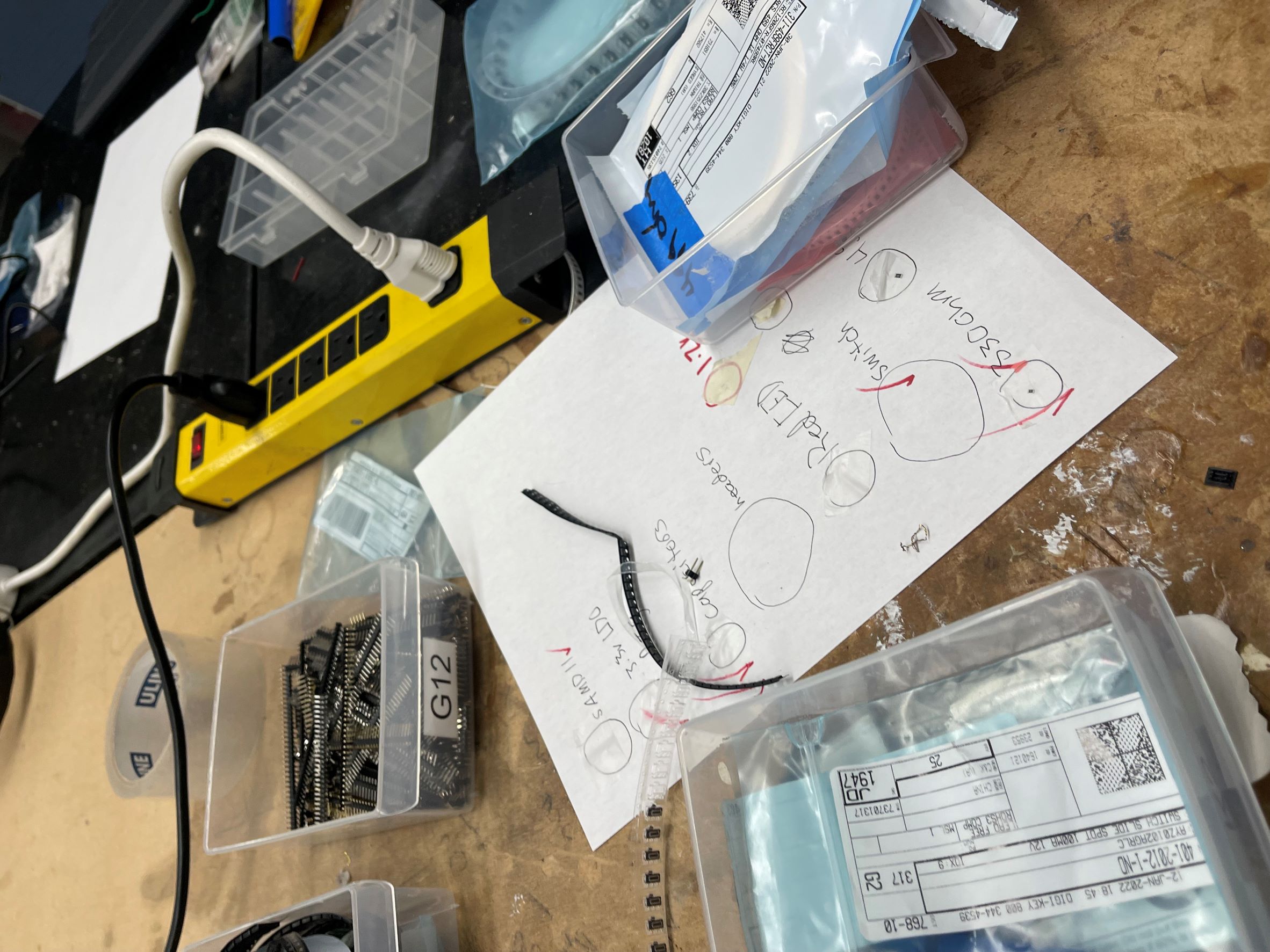
Soldering
The next step was to solder the components onto the board. The most trouble I had with this part was finding all the correct components.
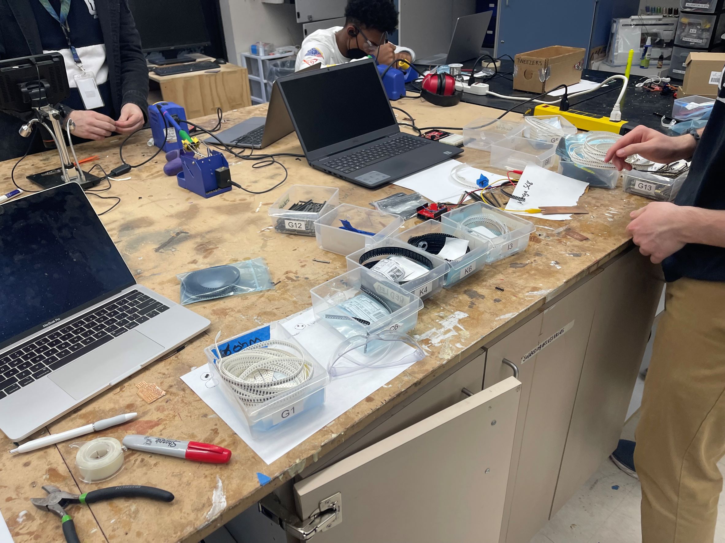
After I did that and labeled them all out and had them on my paper I started to get to soldering.
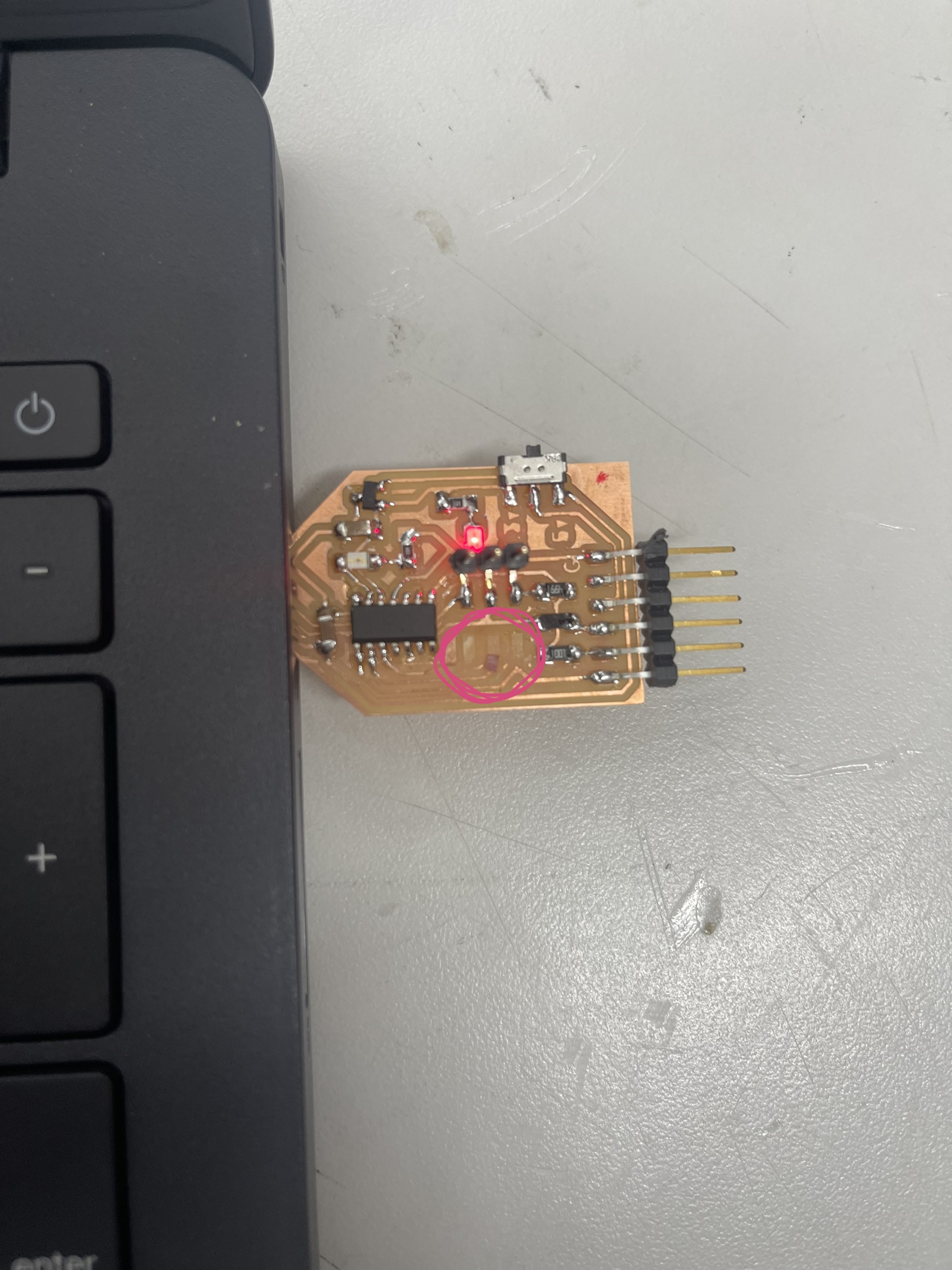
I soldered the board pretty quickly, soldering is one of my strong suits so it took about 15-20 minutes to finish the board. I was very cautious about putting on the chip with the small dot facing upwards beacsue I have messed that up in the past. Also putting the LED lights on with the ground on the boards ground was something I had to remember. I looked at the board schematic so I did not mess that up. After I made sure that was right I finished the board and then it was time to check it. I was very nervous because there was many small reasons why it could not work. I took it to the other room and put it in my computer to see if the boards power LED would turn on. First I needed to get and Exacto knife and scrape off extra copper on the usb part so it would not fry my usb port. Next time I will definetely get rid of that extra copper on the milling machine. Then I plugged it in and it worked first try.
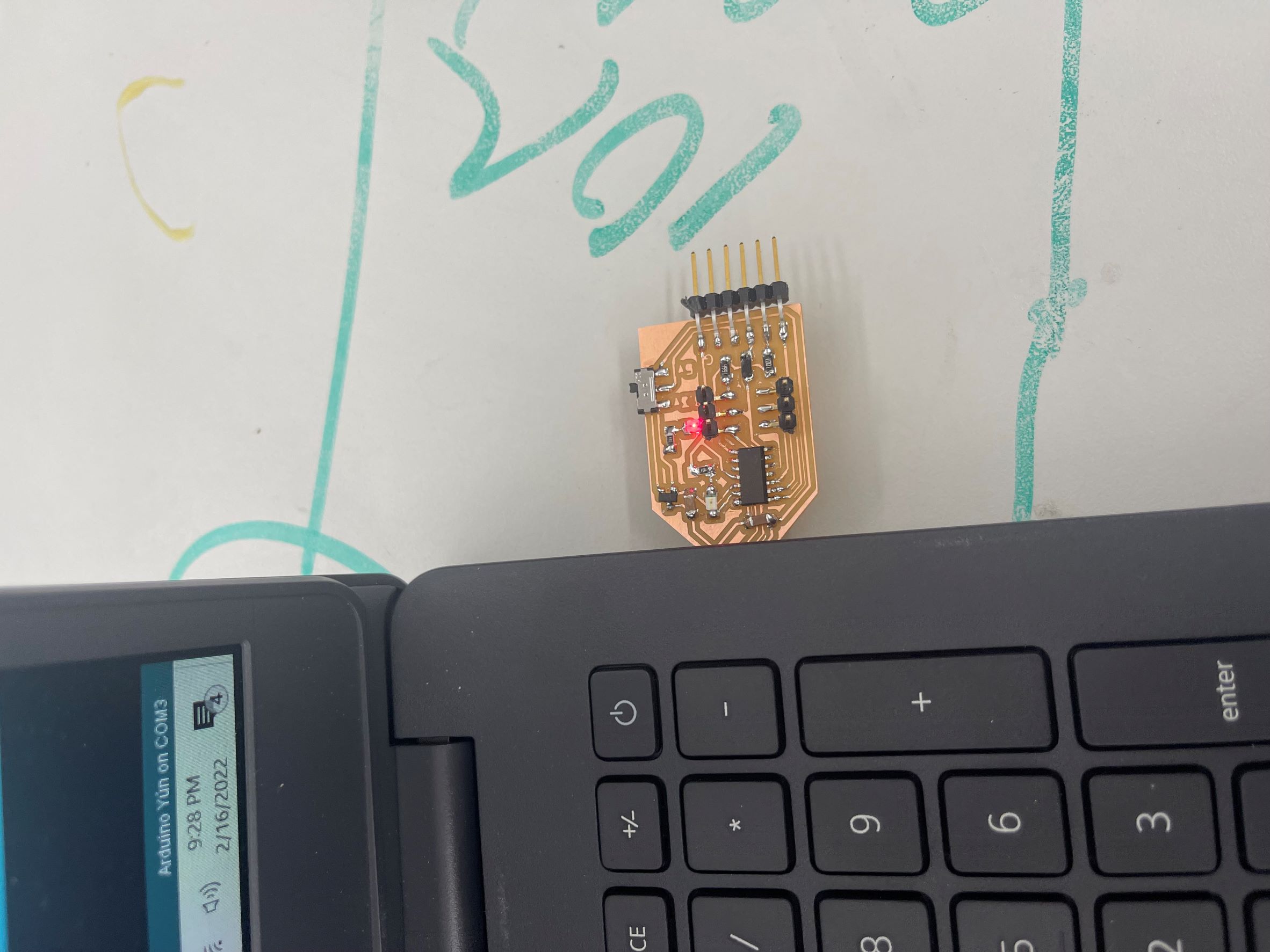
I was escatic. I struggle with programming and code but soldering is something I am good at so I am happy that it worked perfectly first try.
Programming
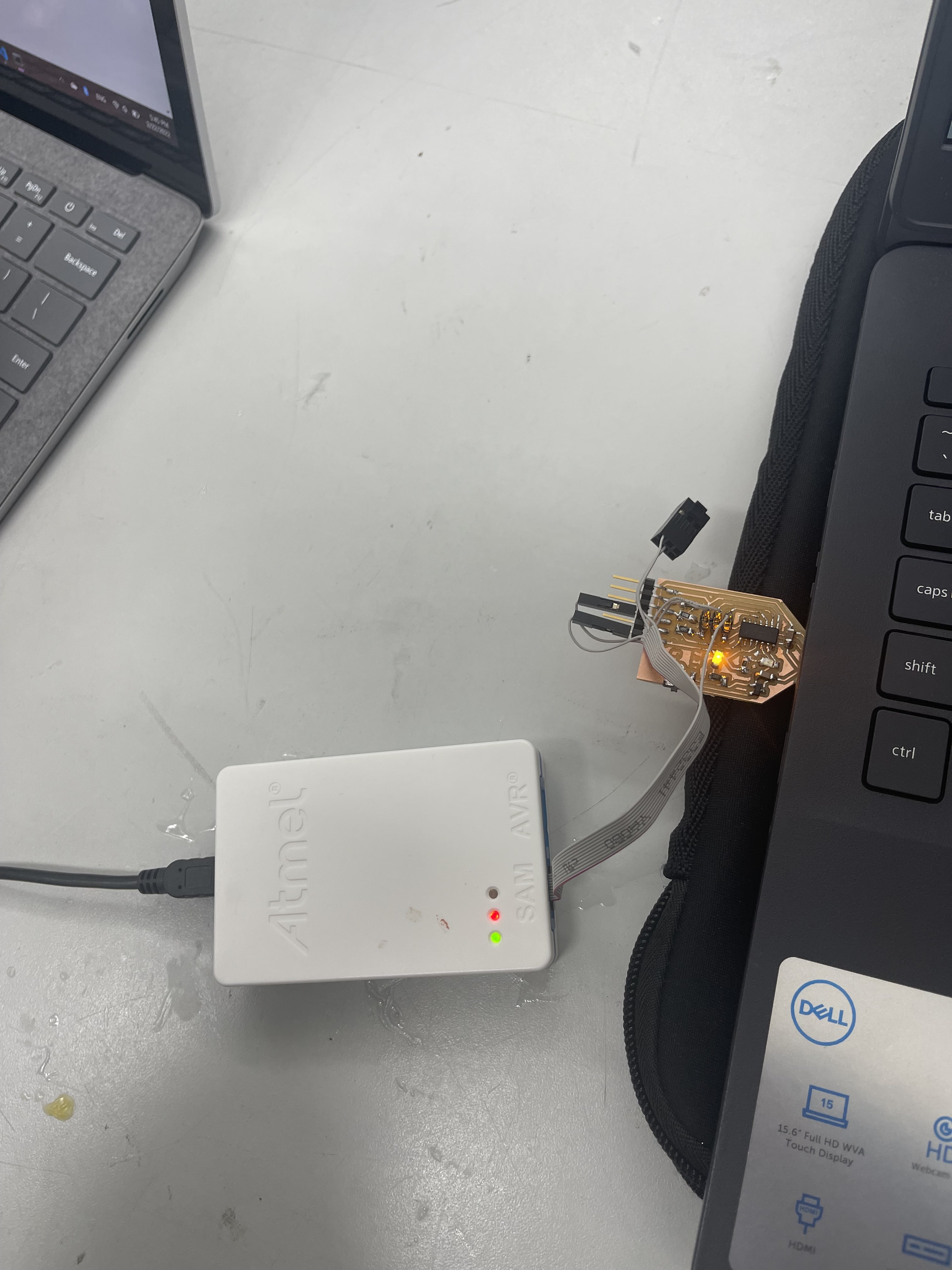
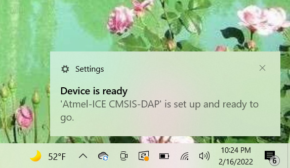
First I used Dr. Harris’s Site again to program my board. I am not the best programmer so this took longer than the physical process of making the board itself. I first connected the board into the computer then into the ATMEL-ICE and started to download the edbg and arduino firmware.
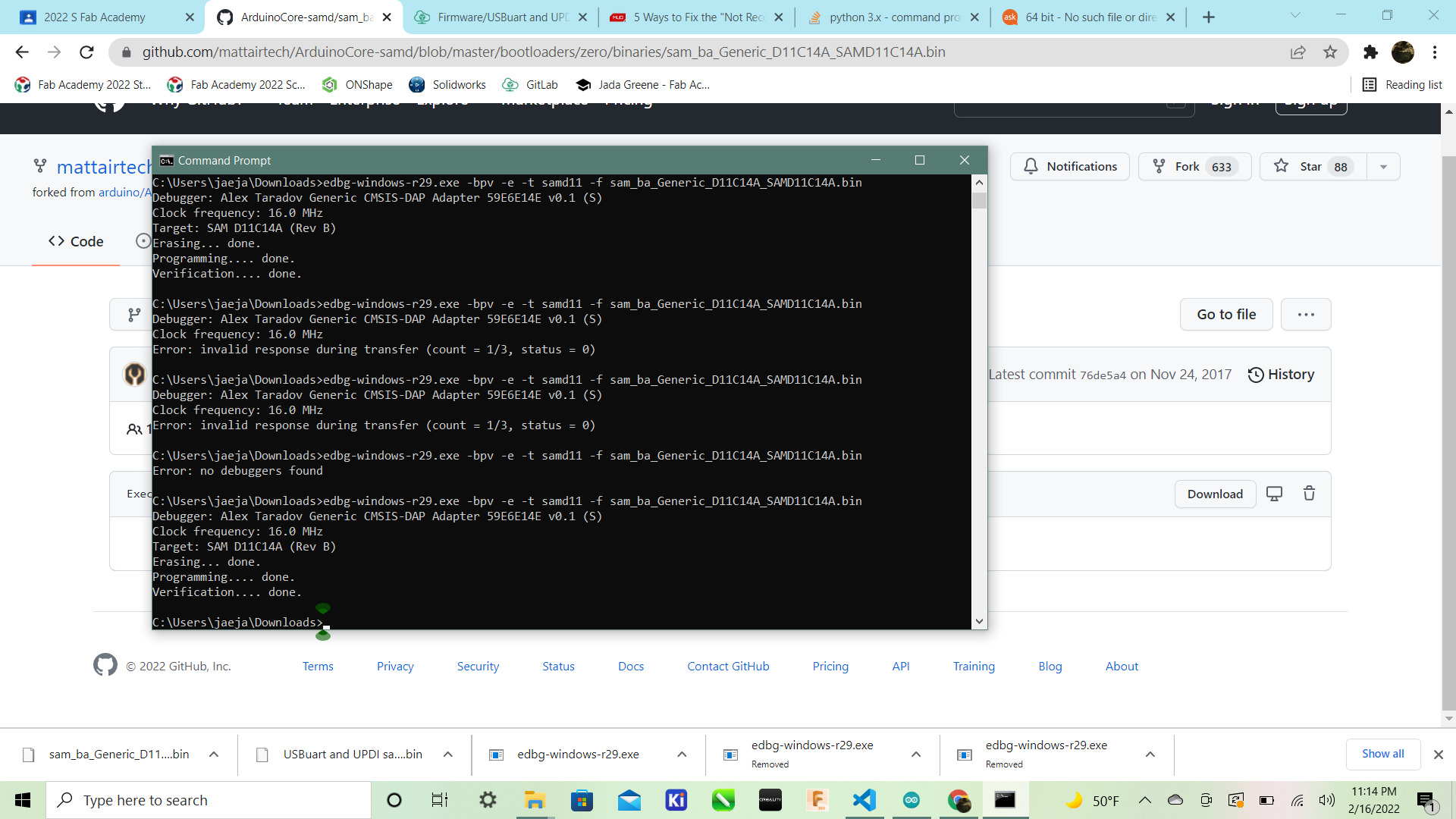
They have to be in the same folder to be used simultaneously. Then I ran this command into windows “Command Prompt”:
edbg-windows-r24.exe -bpv -e -t samd11 -f sam_ba_Generic_D11C14A_SAMD11C14A.bin
At first I got this error:
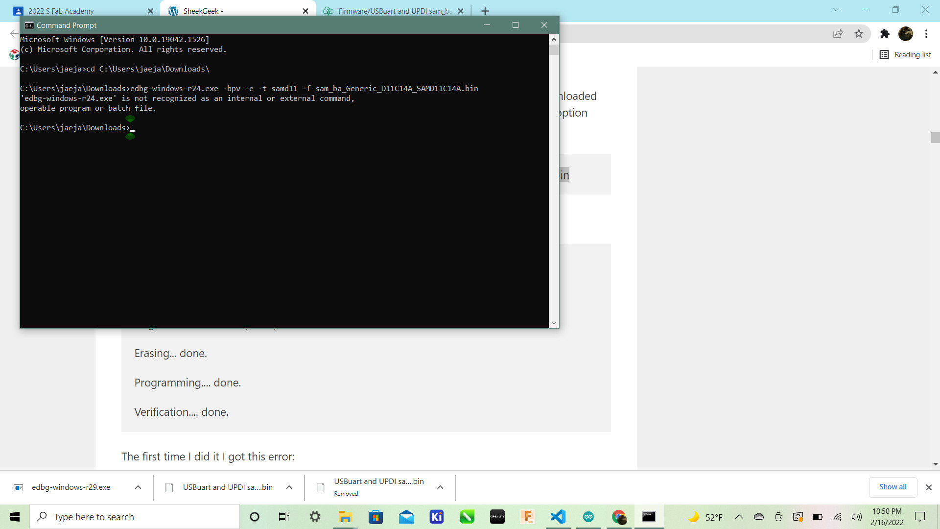
Then I realized it was because the command for the R24 download while I downloaded the latest version which is R31. So the simple fix was to change 24 to 31 then rerun the code.
edbg-windows-r31.exe -bpv -e -t samd11 -f sam_ba_Generic_D11C14A_SAMD11C14A.bin
After running that I got this confirmation:
Debugger: ATMEL Atmel-ICE CMSIS-DAP J42700050854 01.00.0021 (SJ)

Clock frequency: 16.0 MHz

Target: SAM D11C14A (Rev B)

Erasing... done.

Programming.... done.

Verification.... done.
After that I went to arduino. Then I pasted this link:
https://www.mattairtech.com/software/arduino/package_MattairTech_index.json
into the arduino IDE file>preferences. Then after that I went to boards > boards manager and downloaded the Mattair Tech board.
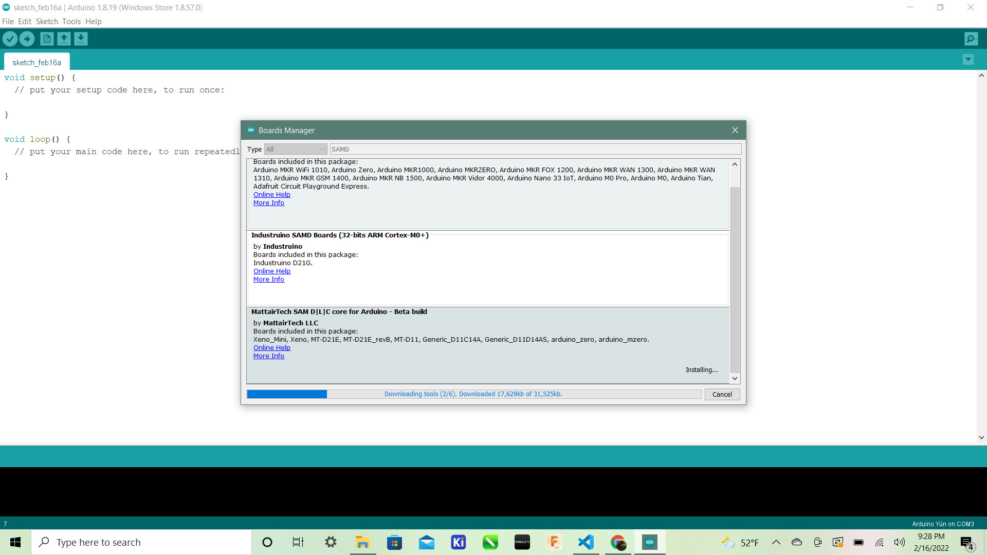
That took a minute but it finally downloaded. Then we uploaded the code to see if code could communicate with the board or not, basically the real test of if the board worked or not.:
int led = 2;

// the setup routine runs once when you press reset:
void setup() {
  // initialize the digital pin as an output.
  pinMode(led, OUTPUT);
}

void loop() {
  digitalWrite(led, HIGH);   // turn the LED on (HIGH is the voltage level)
  delay(1000);               // wait for a second
  digitalWrite(led, LOW);    // turn the LED off by making the voltage LOW
  delay(1000);               // wait for a second
}
I used the blink code to blink my light but I kept getting this error:
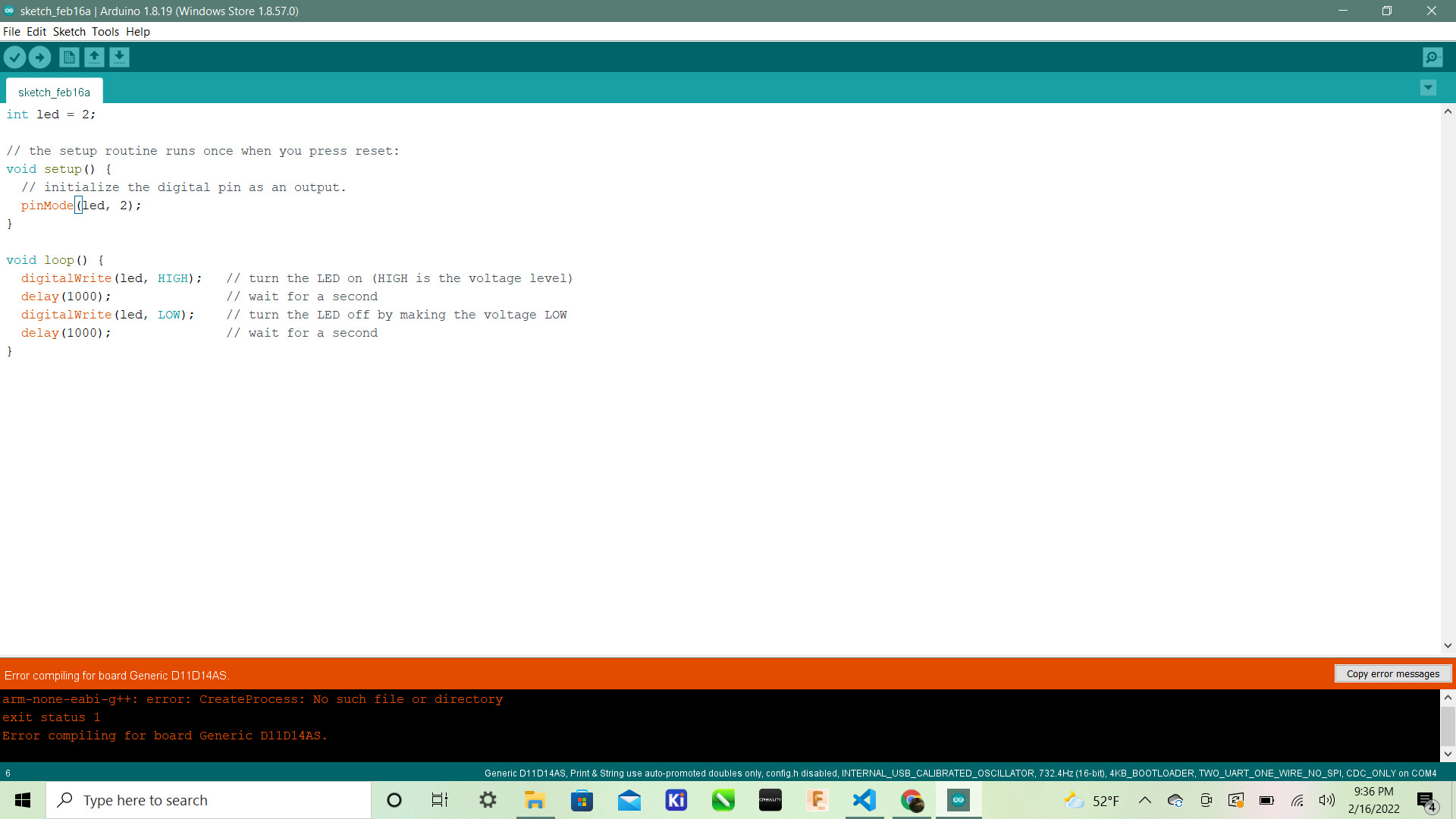
I looked up the error to no avail. So I eveuntually uninstalled arduino IDE and just downloaded arduino. suprisingly that worked so I redid all the steps above and reloaded the blink code. Then it worked. After getting my board to work Dr. Harris used my board to make it able to be a programmer, esentially govong my board the ability to program other boards with this code:
void setup() {

   SerialUSB.begin(0);
   Serial1.begin(57600, SERIAL_8E2); //Adjust baud rate and use SERIAL_8N1 for regular serial port usage
}

void loop() {
   if (SerialUSB.available()) {
      Serial1.write((char) SerialUSB.read()); //Send stuff from Serial port to USB
   }
   if (Serial1.available()) {
      SerialUSB.write((char) Serial1.read()); //Send stuff from USB to serial port
   }
} //end loop
This was it for this week. I felt really great about this week and felt confident in using the milling machine which was the hardest machine I have learned how to use yet probably right after the embroidery machine. I learned how to cover bit so they dont fall and break when replacing them, how to fix broken bands, and how to mill in general. I also did not know that after milling the board we could put the board under the water to wash it off. That is something I didnt know was possible. In all I learned a lot this week and got to hone my soldering skills and definetely get a better understanding of programming. Also After I had already finished all of my work I had the “wise” decision to put the chip in my bookbag which was a horrible idea. One set of the pins broke off. So I will have to mill another.
Design Files
Here is the Design File for this week from Sheek GEEK : Files
Group Work
This week we used our Group Site to showcase our refined design bantam tool workflow.