Meditation Machine
I thought this would we a fun post-fab project that showcased a collection of the skills I learned. It is now the August after Fab ended in July and I am now in my Senior year of high school. I am doing this project in my “Honors Advanced Topics in Engineering” class right now. So after taking the summer to hibernate after Fab I am ready to start on another big project!
My Idea
I was struggling on finding a project. For about 3 days of class I was just sitting and surfing the web trying to find any inspiration but nothing really spoke to me. I knew I loved lights but I did not want to make another lamp. Then I had an idea. In my religion it is a big part to meditate. My first idea was to make a meditation or alter table but that doesn’t have any electronics in it. Then I went a little bit deeper in the whole idea of meditation itself. It is used to calm you down and slow you down. As a high school student that’s in crunch time with college apps and school work I know what stressed feels like. So why not add something to help make sure that your really at peace. I started these sketches in my journal:

They are not the best but I was just trying to put my foggy idea onto something I could physically see. I have never used a pulse sensor before so this was new to me. I also wanted to incorporate a possible touch sensor and maybe an RFID Sensor but the main focus will be the pulse sensor.
Pulse Sensor
Learning the Sensor
Like I mentioned above I have never worked with a pulse sensor before so I did my research. I found this link that explained what the sensor is and how it works extremely well. After I read up on it I got started with learning how to use it simply. I connected it to an Arduino Uno this is the pin out:

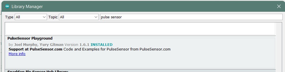
Then I added the PulseSensor Playground Library in Library Managers in Arduino
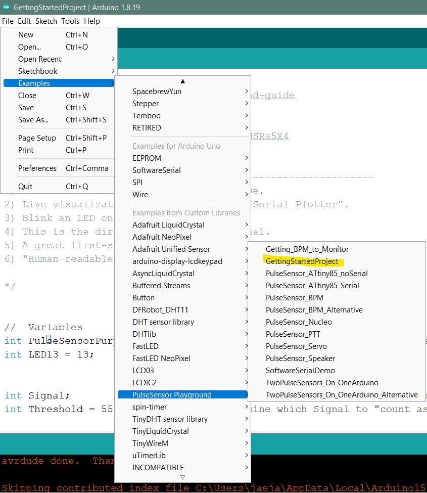
Then I loaded in the “Getting Started Code” in the library’s examples.
//  Variables
int PulseSensorPurplePin = 0;        // Pulse Sensor PURPLE WIRE connected to ANALOG PIN 0
int LED13 = 13;   //  The on-board Arduion LED


int Signal;                // holds the incoming raw data. Signal value can range from 0-1024
int Threshold = 550;            // Determine which Signal to "count as a beat", and which to ingore.


// The SetUp Function:
void setup() {
  pinMode(LED13,OUTPUT);         // pin that will blink to your heartbeat!
   Serial.begin(9600);         // Set's up Serial Communication at certain speed.

}

// The Main Loop Function
void loop() {

  Signal = analogRead(PulseSensorPurplePin);  // Read the PulseSensor's value.
                                              // Assign this value to the "Signal" variable.

   Serial.println(Signal);                    // Send the Signal value to Serial Plotter.


   if(Signal > Threshold){                          // If the signal is above "550", then "turn-on" Arduino's on-Board LED.
     digitalWrite(LED13,HIGH);
   } else {
     digitalWrite(LED13,LOW);                //  Else, the sigal must be below "550", so "turn-off" this LED.
   }


delay(10);


}
Then I uploaded the code. This is how it turned out:
VIDEO
Next I am going to try something even more complex. I found this link which is like a baseline of everything I want to do.