Group Assignment #5: Computer-controlled Machining
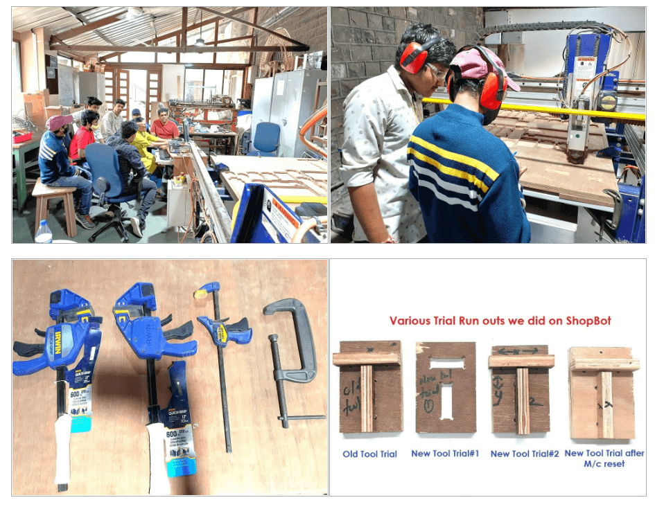
This assignment is about documenting what we learned in Computer-controlled Machining week that includes doing our lab's safety training. After doing this training, we did a few test runouts on shopbot, we checked machine alignment, fixturing requirements, speeds, feeds, materials, and toolpaths generation during test runouts on the machine. We cut a few sample parts with slots and projections (T-shape) to understand the machine accuracy, tolerances and fitments in press-fit joints. Based on the measurements of these test jobs, we concluded on design parameters for the press-fit joints.
Objectives of the Group Assignment:-
To do our lab's safety training
To do test runout, understand- alignment, fixturing, speeds, feeds, materials, and toolpaths
for our machine
CNC:-
CNC machining is a procedure in which computers are utilised to control machine tools in the
manufacturing industry. Lathes, mills, routers, and
grinders are examples of tools that can be controlled in this way. CNC stands for Computer
Numerical Control in CNC Machining. On the surface,
it may appear that the machines are controlled by a standard PC, but the computer's
specialised software and control console are what truly distinguishes
the system for CNC machining.
Specifications of Shopbot:-
Sheet Material upto Size:
4’x 8’ with machining depth (Z axis) of 6 inches.
Table Size:
6’x 10’
Step Resolution:
0.0005’ or better depending on the gear ratio
Positioning Accuracy:
+/-0.0005” or better(No load)
Positioning Repeatability:
+/-0.003” or better(No load)
Cutting Accuracy:
+/-0.015” or better for heavy cutting applications
Simultaneous Linear Interpolation:
3 dimensional
X,Y Cutting MOvement Speed:
240”(standard)/600(Alpha) per minute
X,Y Rapid Positioning Speed:
600”(standard)/1800”(Alpha) per minute
Z Axis Move Speed:
360” per minute
Linear Force:
60-75(standard)/150-200(Alpha)lb. at 60° per minute, depending on gearing.
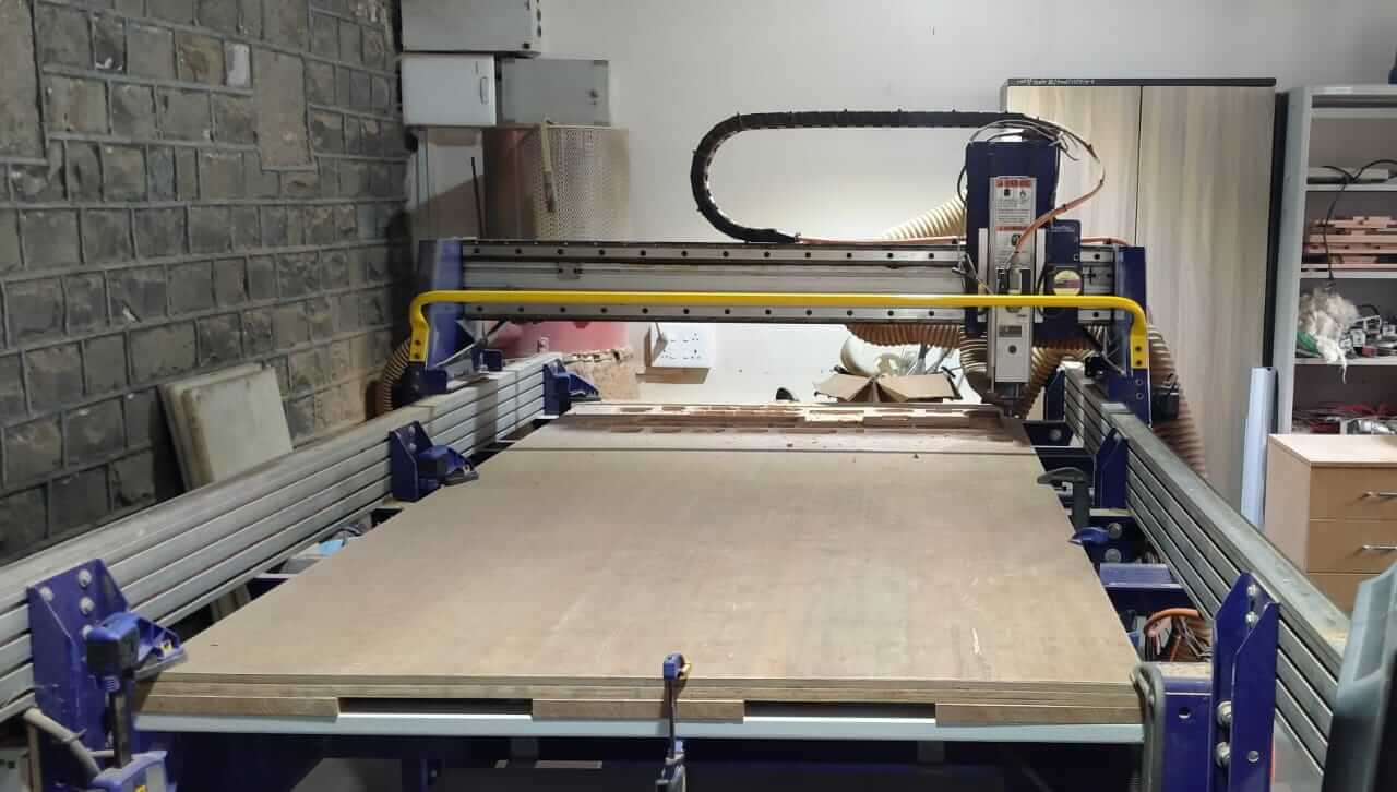
Our Shopbot:-
CNC machining refers to the numerical control of machine tools. The machines are programmed
with CNC machining language (called G-code), which fundamentally
controls all aspects such as feed rate, coordination, location, and speeds. The computer can
regulate precise placement and velocity using CNC machining.
Both metal and plastic parts are manufactured using CNC machining.
A CAD drawing (either 2D or 3D) is prepared first, followed by a code that the CNC machine
can interpret. The program is then loaded, and an operator conducts
a test on it to ensure there are no errors. Cutting air is the term for this trial run,
which is crucial since any errors in speed or tool location could
result in a scrapped part or a broken machine.
.
There are numerous benefits to CNC machining. The procedure is more precise than manual
machining, and it may be repeated in the same way over and over.
CNC Machining can make intricate designs that would be nearly impossible to achieve with
manual machining due to the precision available. Many sophisticated
three-dimensional shapes are created with CNC machining. CNC Machining is employed in
projects that require a high level of precision or that require a lot
of repetition because of these characteristics.
A background in mathematics, industrial arts, and mechanical drafting, as well as computer
skills, would be advantageous.
Sacrificial Layer - x:-
The Shopbot machine's bed is constructed of metal, so we have to put a flat layer of plywood
on top of it as a sacrificial layer to protect it. Because the
endmills will cut into the sacrificial layer if they dive deeper than the thickness of the
material, the sacrificial layer is critical.
Our primary element is clamped over the sacrificial layer while it is being cut.
Overview of CNC Milling Process:-
Designing a CAD model
Converting the CAD model into a CNC program
Setting up the CNC milling machine
Executing the milling operation
Outlines:-
feed rate
coordination
location
speeds
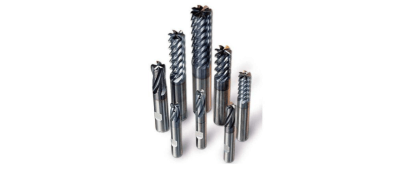
End Mill:-
End mills are tools with cutting teeth on one end and on both sides that are used for a
range of tasks such as facing edges and cutting slots
and channels. End Mills are available in a number of styles and materials, including
High-Speed Steel, Cobalt Steel, and Carbide.
There are also numerous variations for the number of flutes, which typically range from two
to eight. Finally, there
are roughing and finishing end mills for each style.
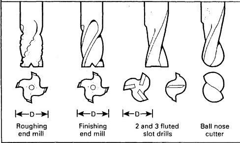
Flute Diagram:-
This is a diagram of a flute. From the bottom, it displays how a two flute, three flutes,
four flutes, six flutes, and eight flute mill end appears.
The arrows then indicate that while cutting a harder material, you should travel to the
right, and when cutting a softer material, you should go
to the left to remove more chips.
What’s a Router?
It's useful to know how to use a handheld router before talking or using a CNC router. A
standard router has a motor (potentially a variable speed motor),
height adjustment (fixed or plunge), and a collet, which is a tapered spring that generates
the friction needed to keep your cutting tool
in place when squeezed.
What are Toolpaths?
A toolpath is a user-defined programmed path taken by a cutting tool to machine a part. On
the screen, they are represented by lines and curves that
indicate the route of the cutting tool's bottom center. Pocket toolpaths etch the material's
surface, whereas profile toolpaths cut through through it.
Tooling:-
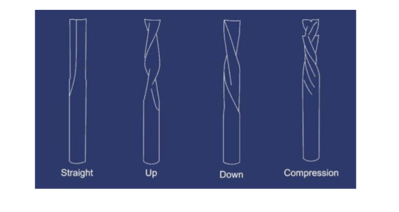
There are four basic flute patterns for router bits, as well as a variety of customised
bits.
Types of bits Straight Flute.
1.great all around bit, decent chip removal Up Spiral.
2.great chip removal, can tear-out the top of thin veneer such as finish grade plywood Down
Spiral.
3.poor chip removal, no tear out, slower feed rate Compression.
4.combination of up and down spiral, great all around bit, great for plywood or laminated
sheet goods.
CNC Machine Safety:-
An Emergency Stop Button
A Soundproof Casing
The Eye Guards
Safety GLoves
DO:-
When using a CNC machine, always wear suitable ear protection and a decent pair of safety
glasses.
When you're closely inspecting the cutting tools, make sure your safety glasses are firmly
in place.
At all times, make sure you're wearing appropriate footwear, such as safety boots.
If you have long hair, make sure it's covered when using the CNC machine.
During machining processes, keep your hands away from any moving parts.
When the machine is on, keep a safe distance from it. You should also advise anyone else who
is close by of the dangers of being too close to it.
Avoid contacting the cutting edges of instruments when handling or passing them.
When you're done using the machine, make sure to switch it off fully and clean it.
DON’TS:-
You should never wear loose clothing or jewellery.
It's never a good idea to reach into a machine while it's running.
When the spindle is spinning, you should never bring your hands near it.
Never leave the machine running if it isn't totally turned off.
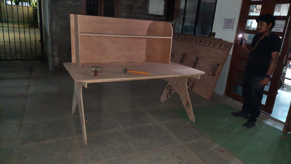
Final Output
What we learned in this assignment
We learned Safety requirements of the machine, shop and tooling. We understood the tooling and fixturing requirements for ShopBot. We also learned machine parameters like, Speed, feed, plunge rate, depth of cut, etc. We used Partworks for toolpath generation.
We would like to thank Ms. Apeksha and her team from College of Engineering, Pune to help us throughout this assignment.
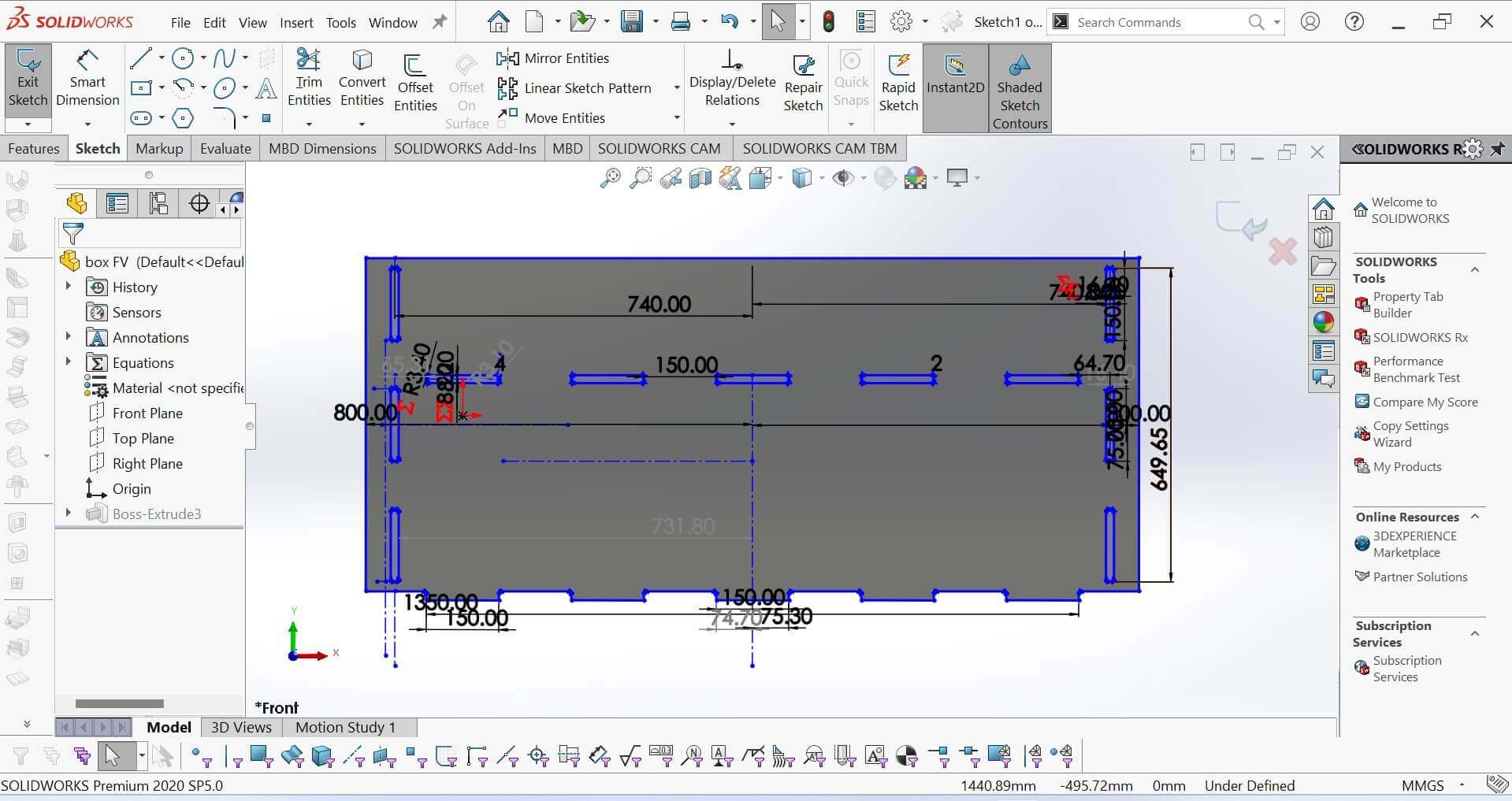
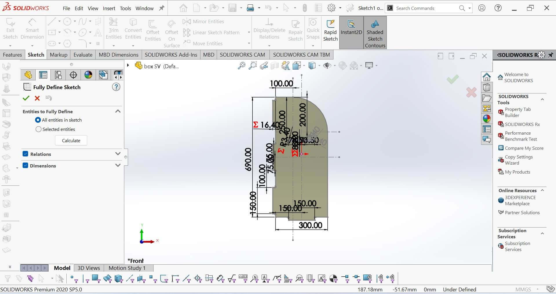
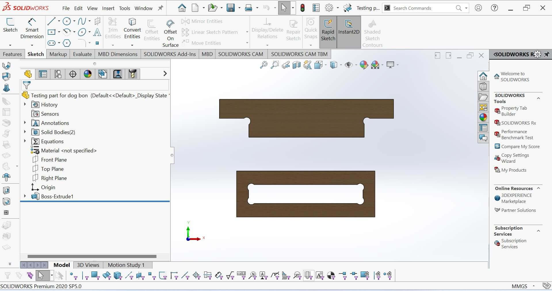
Inside this week, I use SolidWorks software for design.
This is the back plate of my design
parameters
What is the parameters?
Parameter Design - Parameter design is a process that seeks to set main factors so as to achieve a response objective (Maximum, Minimum, Target) while at the same time allowing subsidiary factors to vary in a "customary" way.
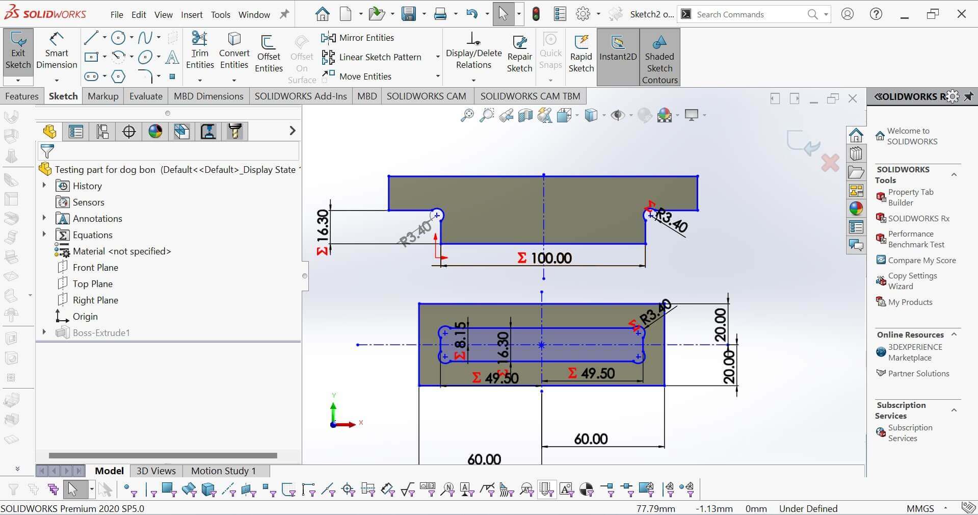
I have used parameters in my design. Inside which I have also used Dogbone inside
So my work was reduced.
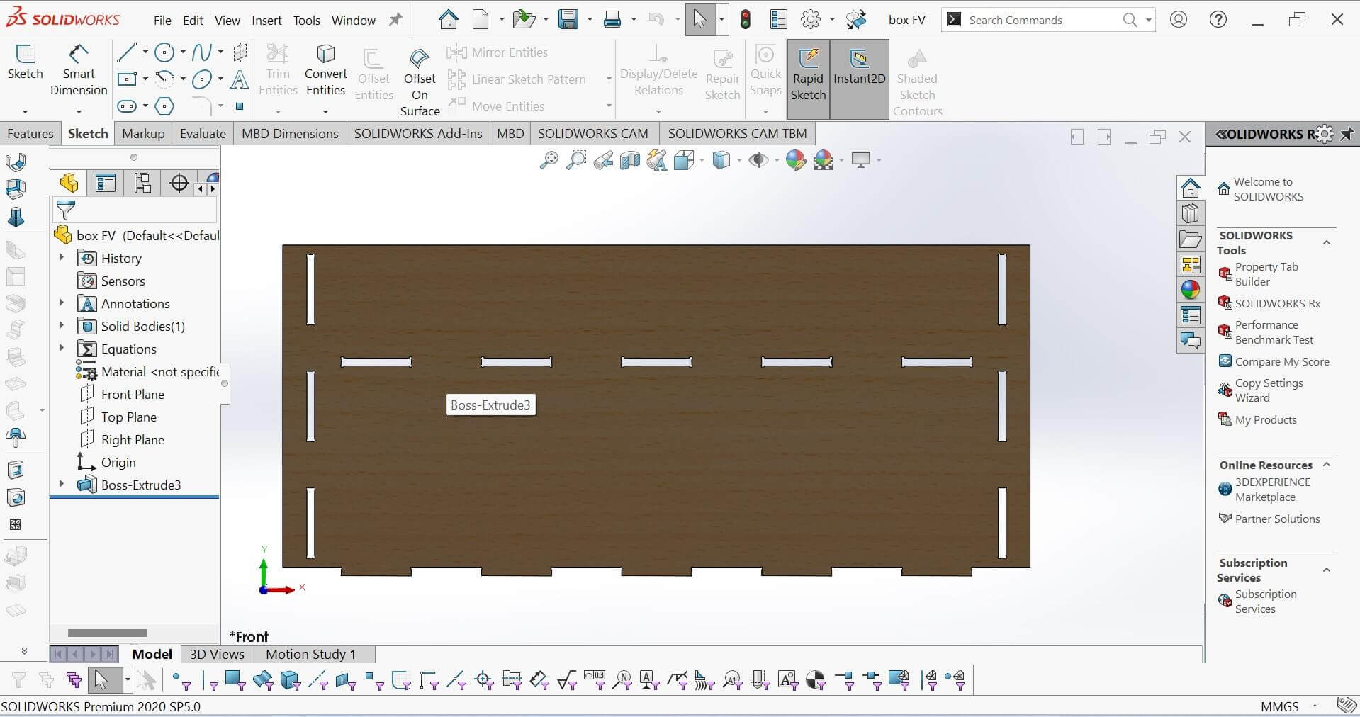
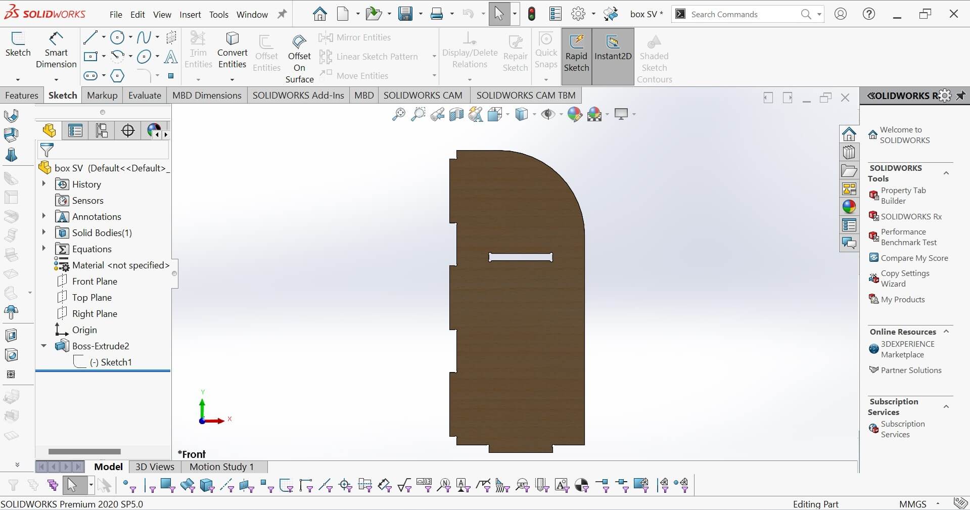
This is the Slide plate of my design
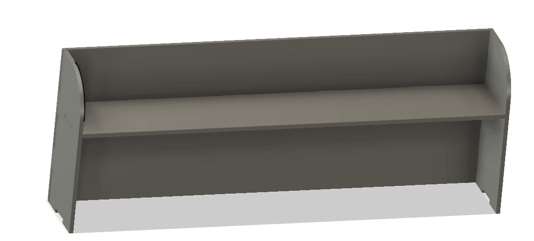
Final Assembly Photo
If the dogbone joint was going to be a joint inside my slot,
it was a bit of a problem for me, but I learned it by watching
a video on YouTube.
Dogbone Reference Video
Dogbones and why are they needed
You are probably familiar with "regular" fillets, but did you know that there is also a
DogBone Fillet?
What is a regular Fillet?
A fillet is used to reduce the sharpness of corners. You can modify corners with fillets
(either a chamfer or curve). A "regular" fillet creates an arc that is always inside to the
edges (see image below).
What is the problem with a regular fillet?
There are cases where an outward curve may be required. For example, when using a CNC
(Computer Numerical Control) router or machine.
In contrast to additive manufacturing (3D printers), a CNC machine uses subtractive
manufacturing to create the end product. In other
words, a CNC machine removes material instead of adding material.
Just like 3D printers, instruction files are given to a CNC machine as a G-Code. G-Code is
the language that defines the "How" for a machine controller. It tells
the motors where to move, how fast to move, and what path to follow. Vector files such as
DXF are used to create G-Code files. However, the problem for a CNC
machine is that the inner corners can never be sharper than the diameter of the cutting
tool. This is because the router bits are round. It is not possible
to get orthogonal corners at perfect right angles when cutting out the sheet materials like
MDF or plywood with a CNC machine, so instead, these corners will
be rounded inwards.
This can cause problems when mating parts as the part tooled might not fit in the formed
hole or slot as shown below:
What is the solution?
A DogBone Fillet is a solution to this problem. Although "DogBone" is a commonly used term
in the field of CNC Cutting and
milling, the first image that came in my mind when I heard the word "DogBone" is my favorite
childhood cartoon series of
Tom & Jerry.
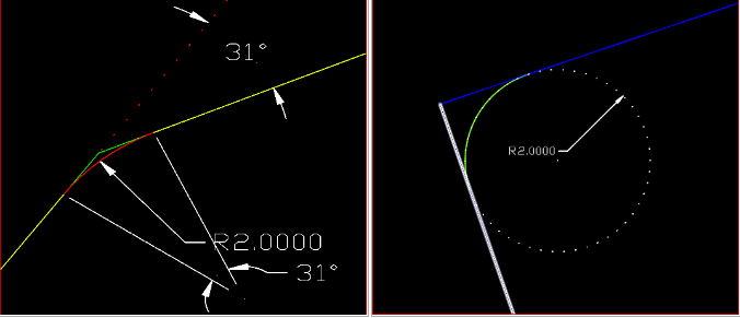
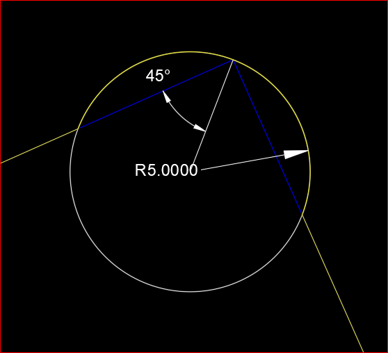
How is a DogBone Fillet diffrent to a normal Fillet?
The DogBone Fillet command is different to a normal Fillet command because it creates a
circular arc that is outside of the edges.
The point of intersection for both edges is actually the mid-point of the arc. By
introducing DogBone Fillets, the object fits
better into the slot:
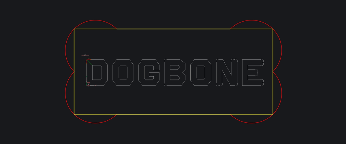
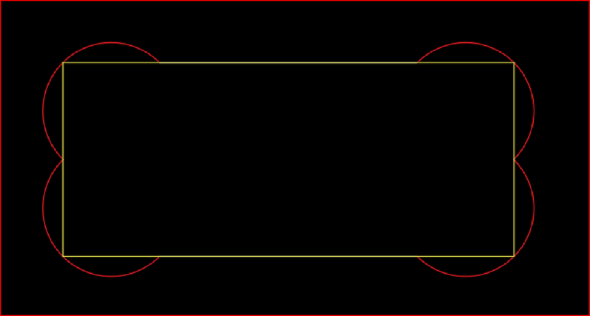
Why is it called a DogBone Fillet?
If DogBone Fillets are created at each corner of a rectangular block, it really looks like a
Dog-Bone!
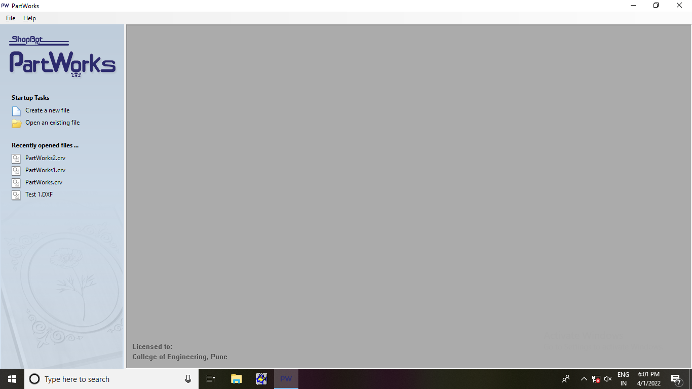
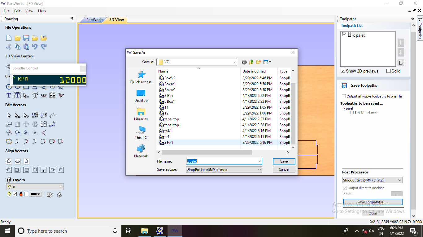
The software used to create toolpaths and deliver Gcode to the CNC Shopbot woodcutter is
called PartWorks.
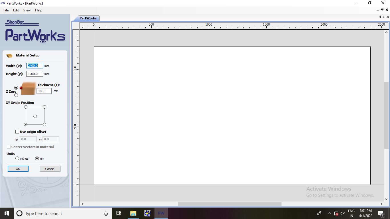
New File
Open New File
updated “Width(x)=2400mm” and “Height(y)=1200mm” and thickness of material “plywood 18mm”.
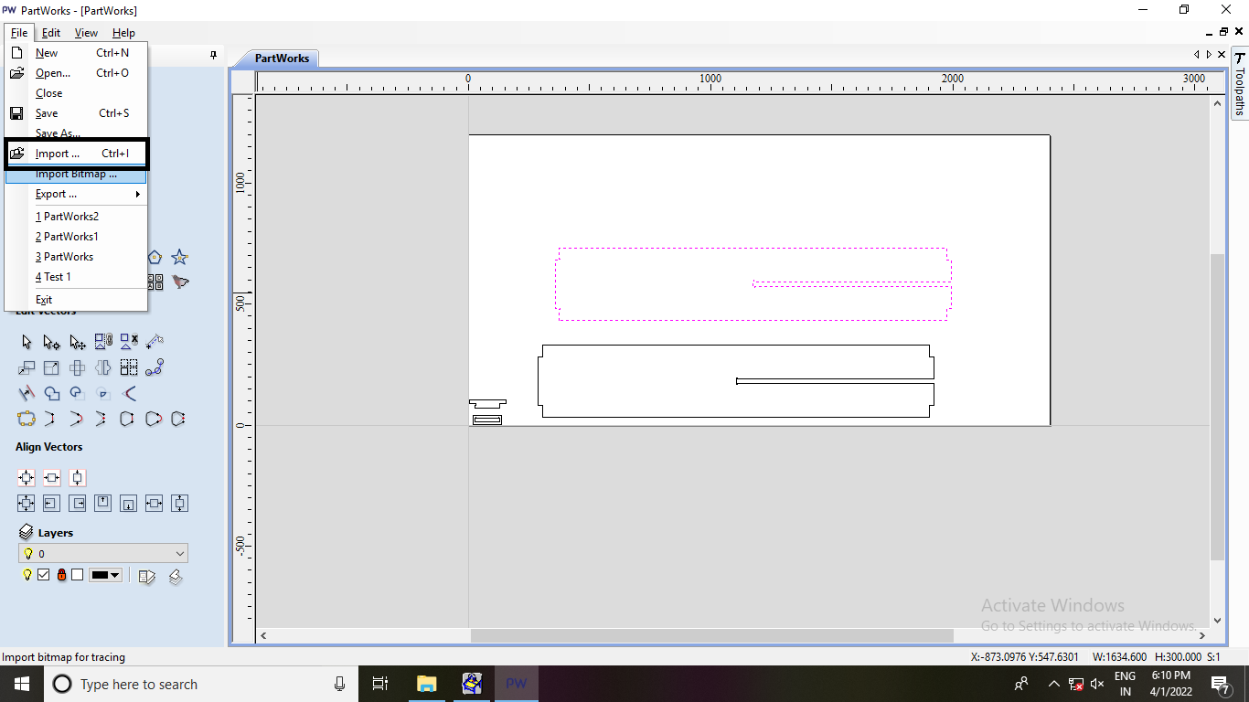
Import
File>Import Opened file designs in .dxf format and arranged them in the bed size selected
above step.
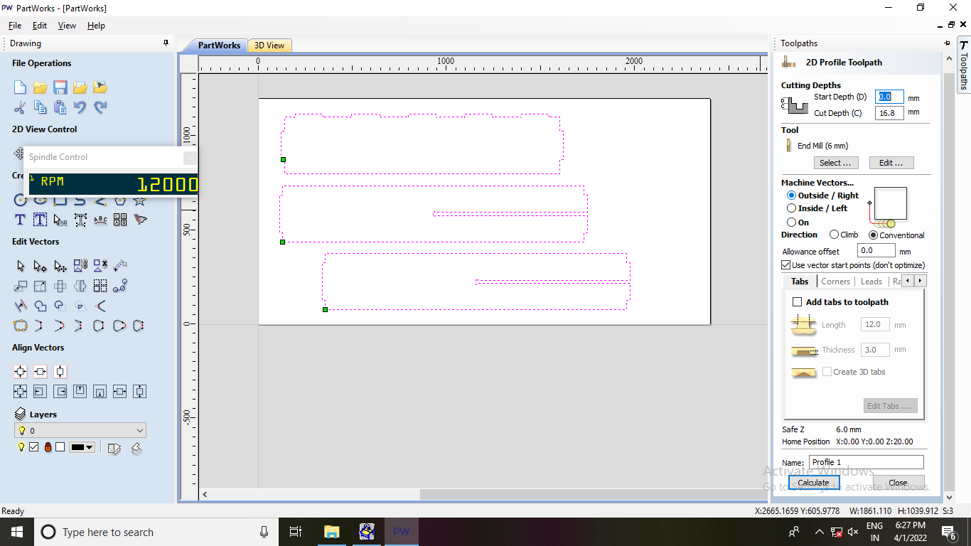
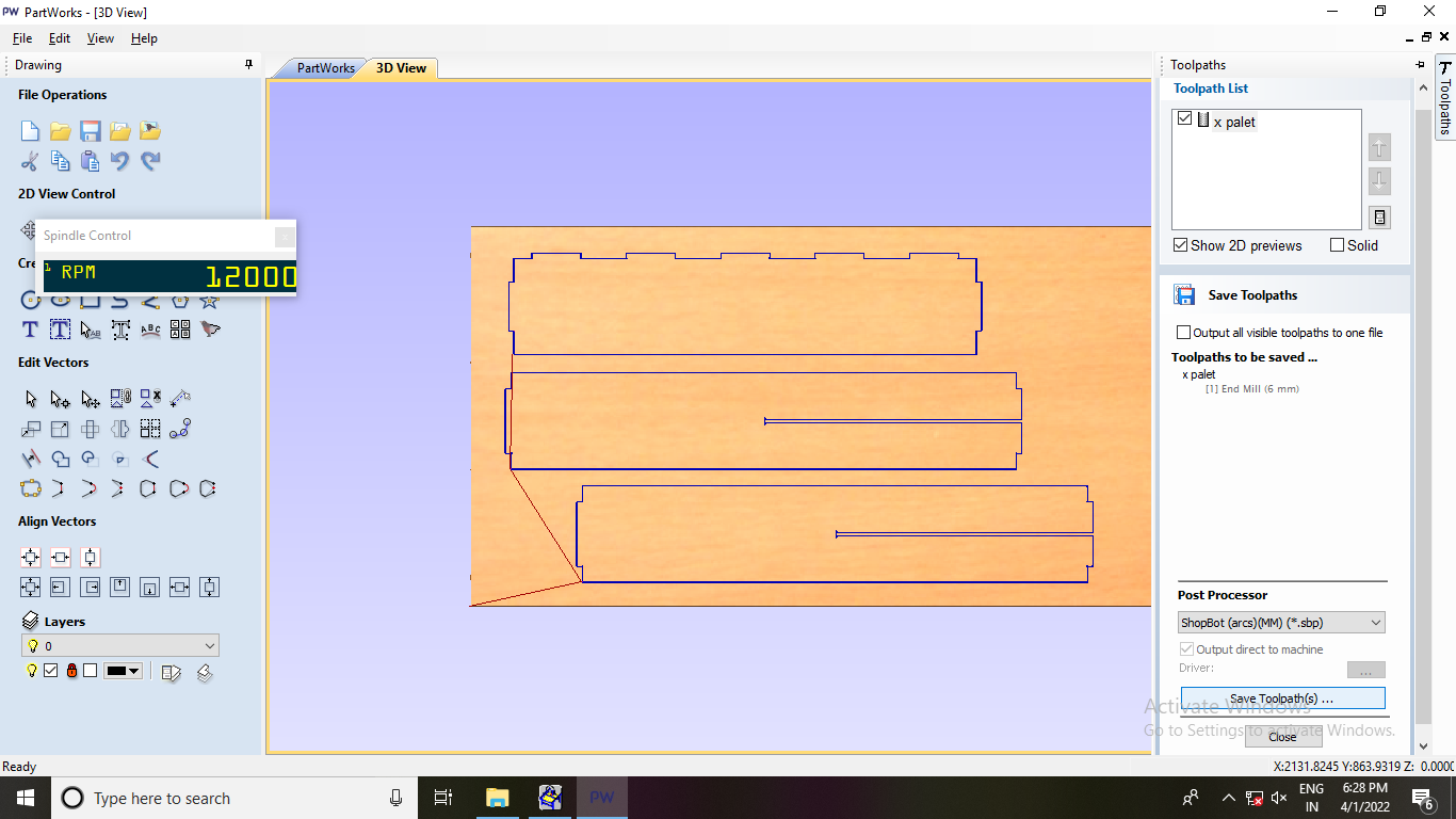
Create Profile Toolpath:
After joining vectors, selected crete profile toolpath and adjusted Start
Depth”0mm” and Cut Depth to “16.8” for 18mm plywood.
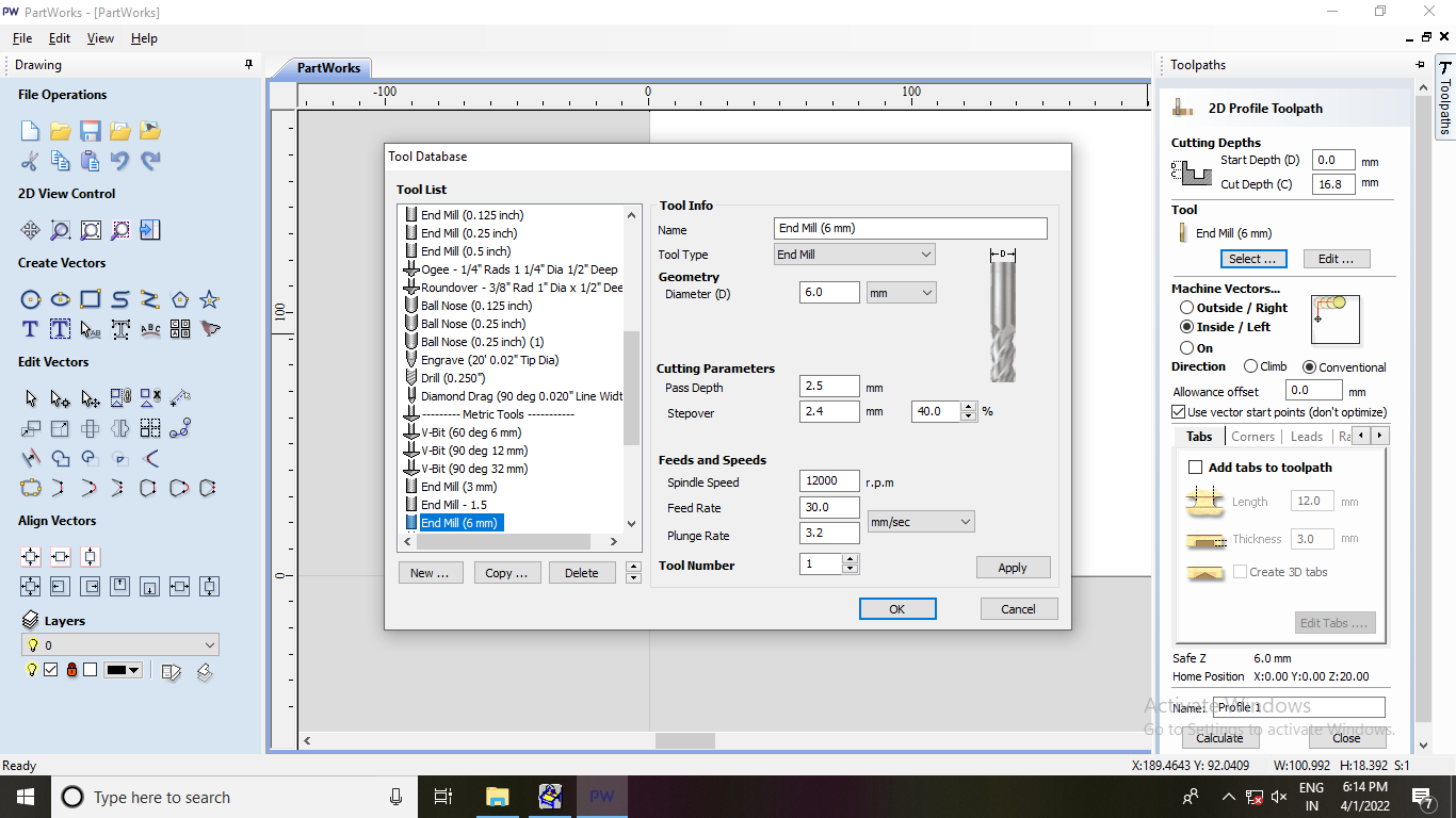
Edited end mill parameters
Diameter of endmill:6.0mm
Pass Depth:2.5mm
Stepover:2.4mm
Spindle Speed:12000 rpm
Feed Rate:30 mm/sec
Plung Rate:3.2 mm/sec
I used the same feed rate that I already had so I didn't make any changes.
Calculated Toolpath
It depicts the direction in which the plywood will be sliced by the end mill.
Toolpath Save
Milling:-
Plywood/MDF Sheet: On the sacrificial layer, place plywood or MDF sheet.
The Shopbot machine's bed is constructed of metal, and to protect it,
we place a flat layer of plywood on top of it as a sacrificial layer.
The sacrificial layer will be cut into if the endmill plunges deeper
than the thickness of the material, hence this extra layer is necessary.
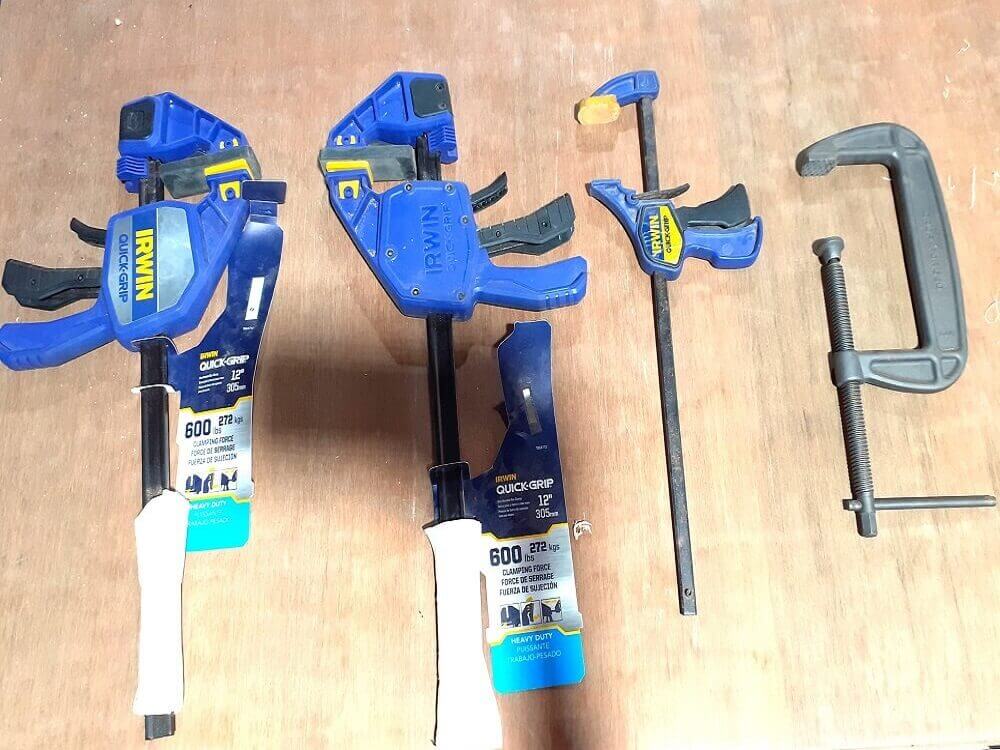
Clamp:
Added clmaps to the corners of the MDF/plywood sheet to keep it straight.
The sacrificial layer and the substance should not have any gaps.
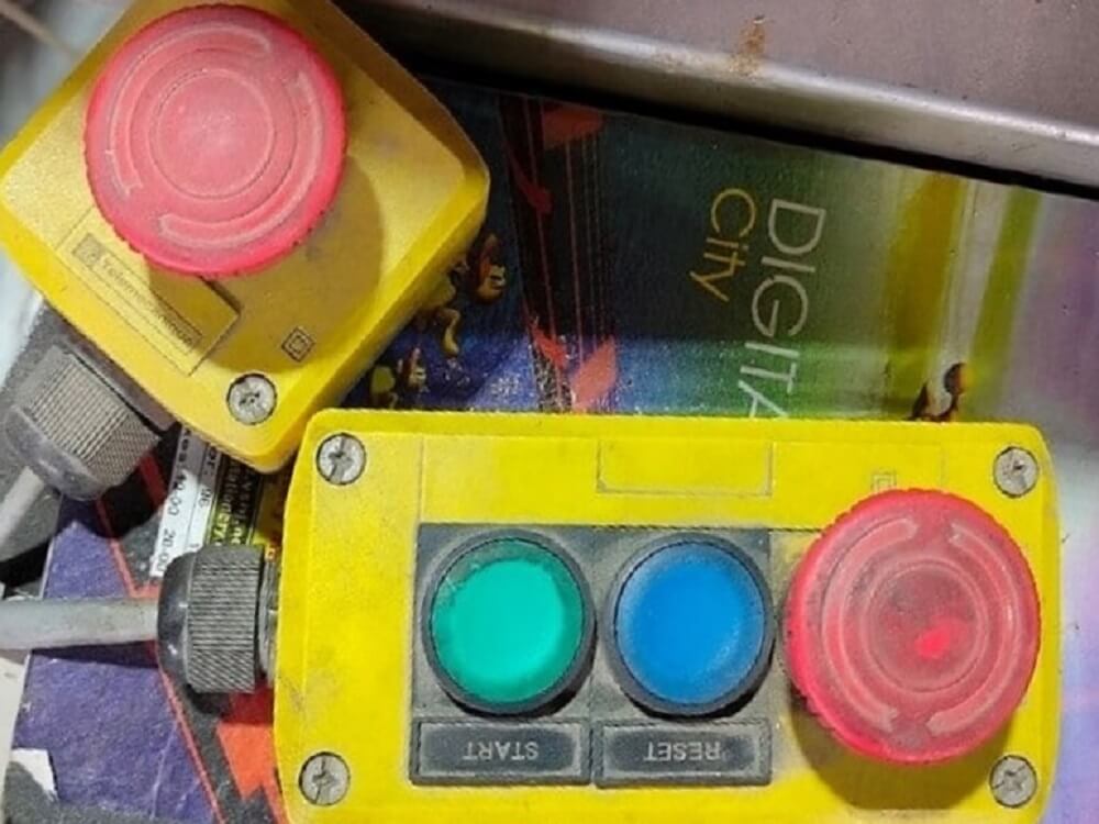
External Control
External 3 buttons can be used to stop, reset, or start the machine in an emergency.
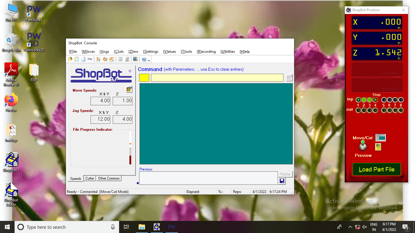
ShopBot Console
To load a part file with a tool path made on PartWorks, I opened the ShopBot position and
ShopBot Console.
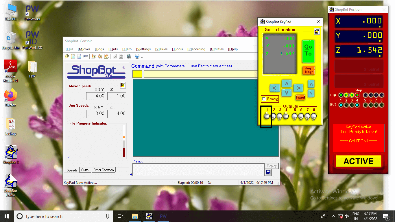
ShopBot Keypad
Click 1 Numbar key and Start Spindle.
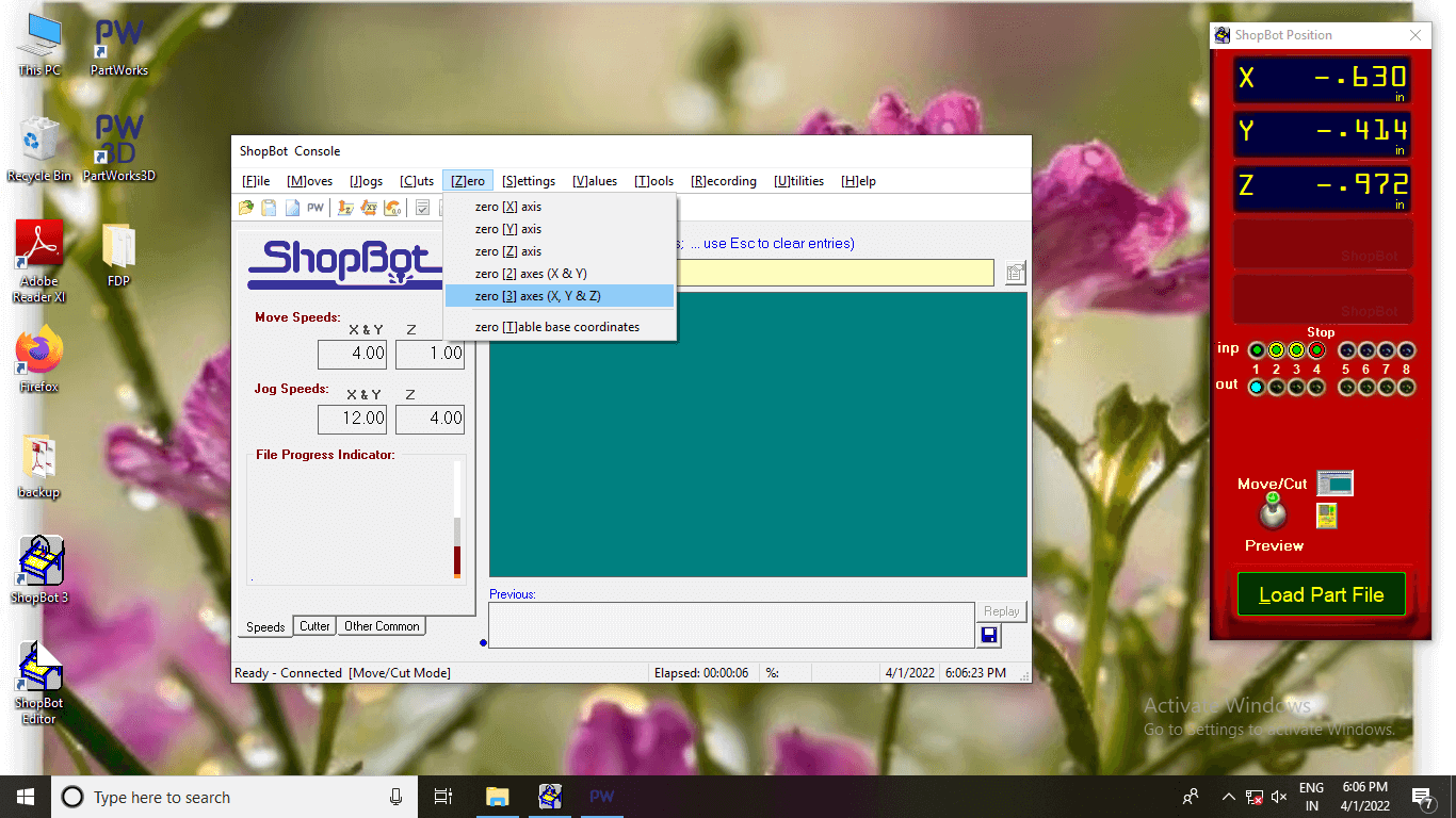
Origin
Origin The endmill was positioned based on the size of the object to be cut. The location of
the endmill was marked as zero[3] axes(X, Y,&Z) on the ShopBot dashboard (0,0,0)
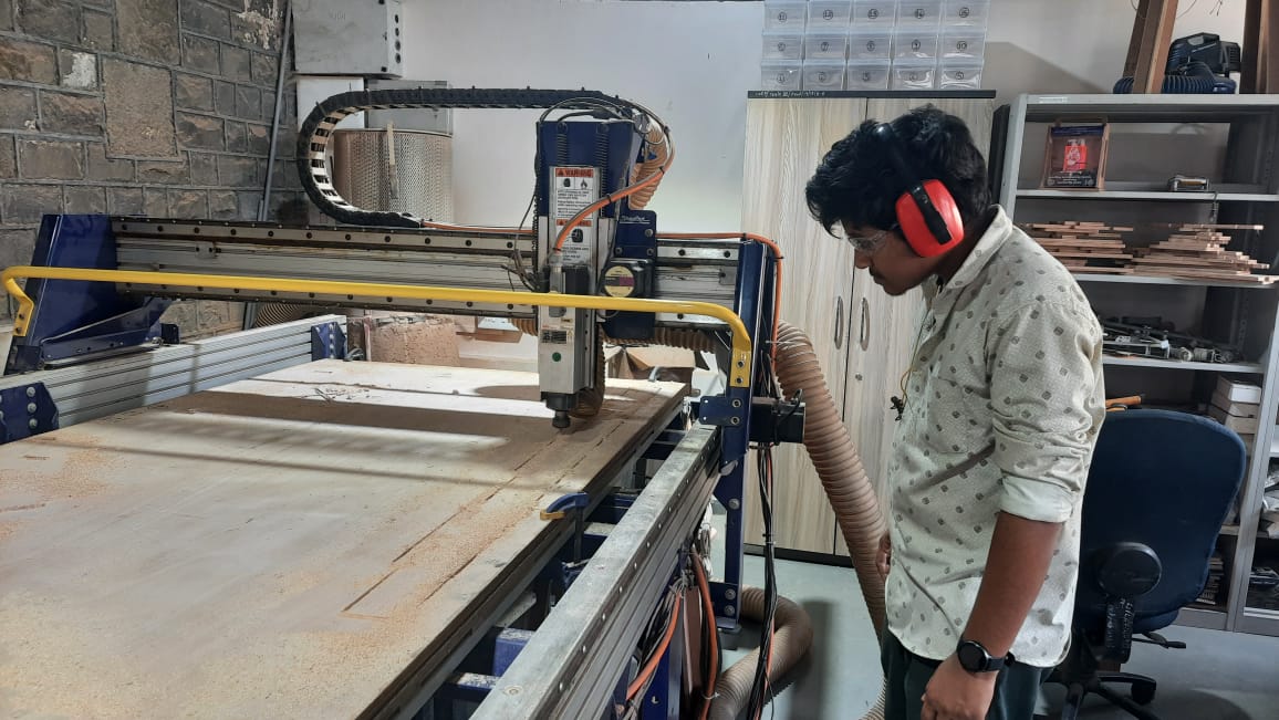
Milling
While the end mill started cutting the components through the plywood, it was quite loud. We
were wearing noise-canceling headphones.
The dust generated during the cutting process was vacuumed up by a vaccum and collected in a
container behind the machine.
Assembly:-
Assembly Video:-
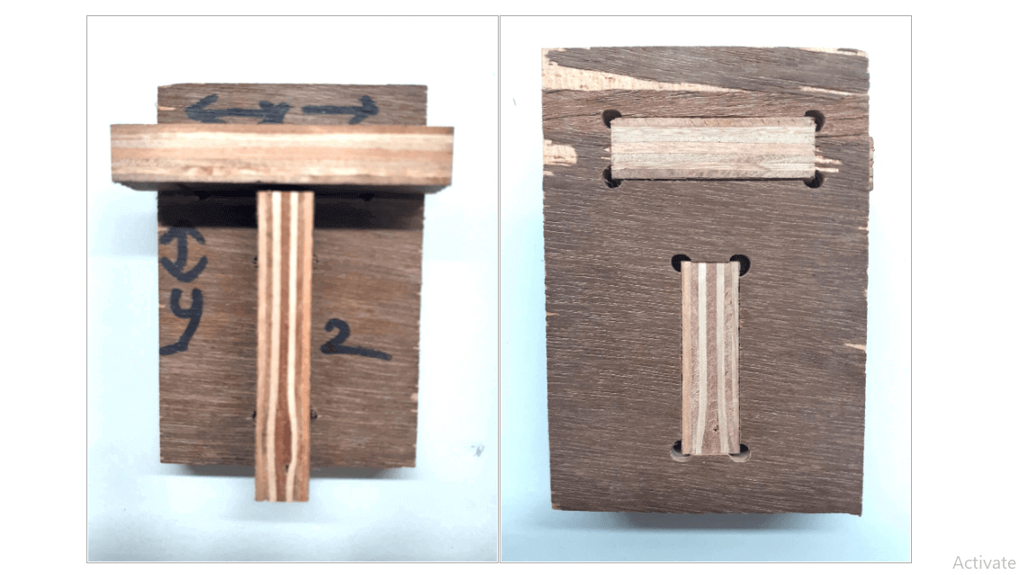
The assembly part of the upper side is made by me and the table below is made by my friend.
So we worked together during CNC Week.