Electronics Design | Week 07
Group Assignment
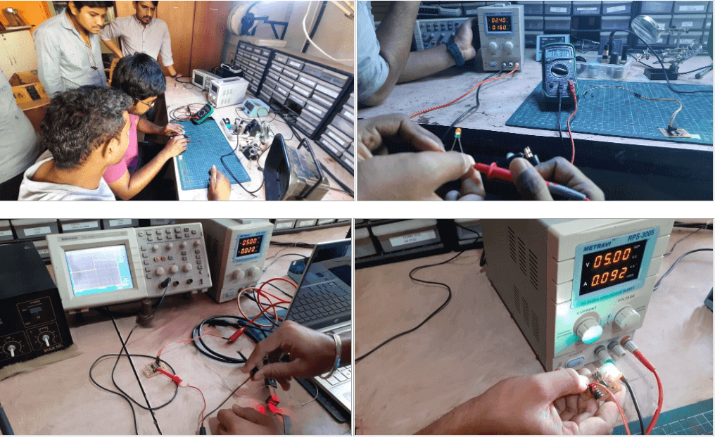
Objectives of the Group Assignment:
Equipment need to be Tested:
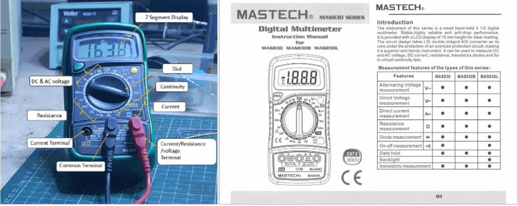
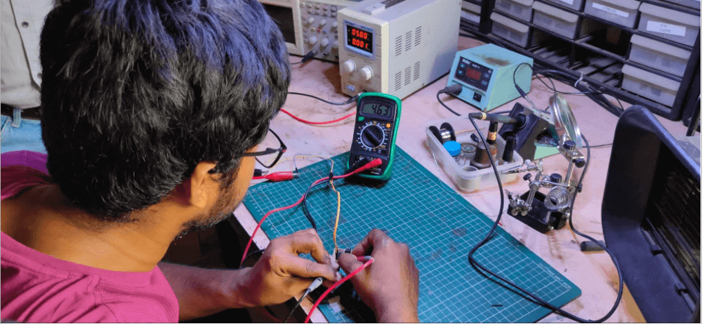
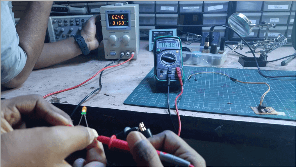
Multimeter:-
Continuity test at LED on the board

Intro
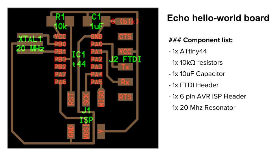
This is the list of materials I'll need to make my Hello echo board.
Component list:-
Additional components:-
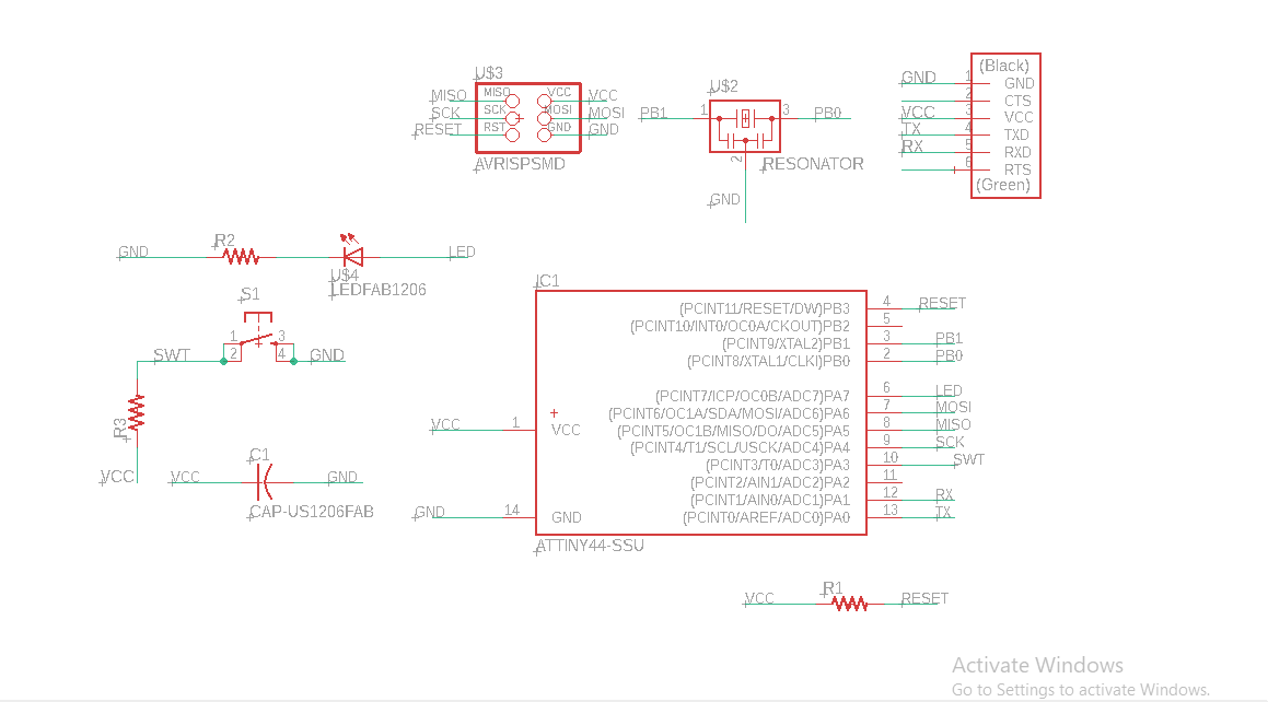
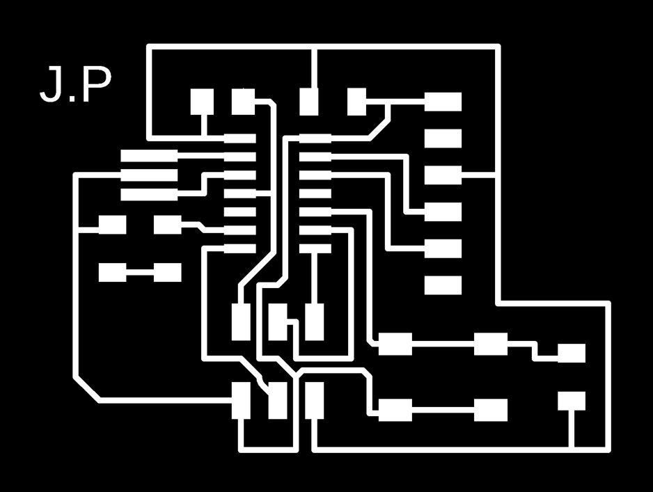
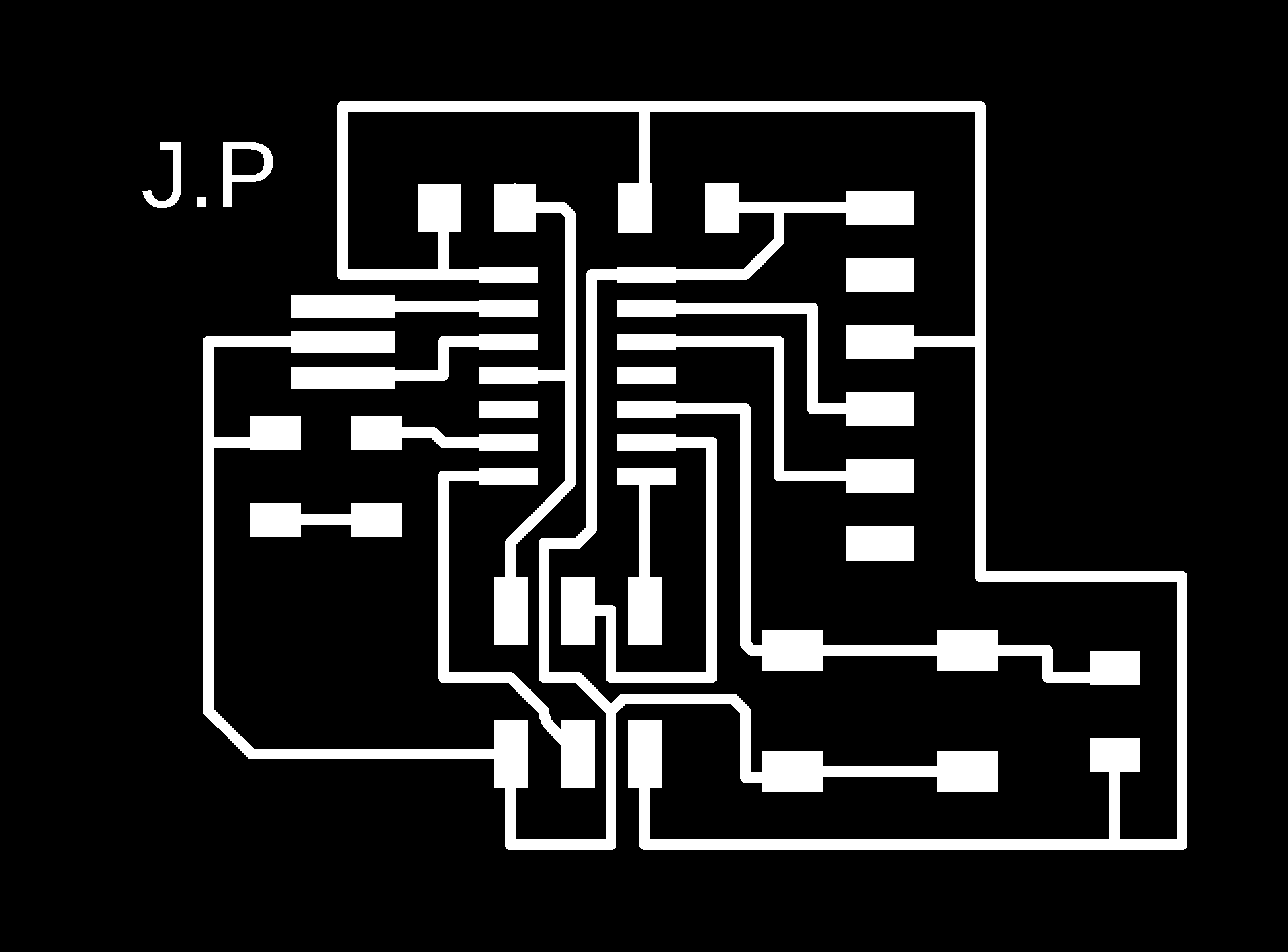
Design
Eagle was used to create the board.
Workflow
why would you want to use fab library when other libraries are available?
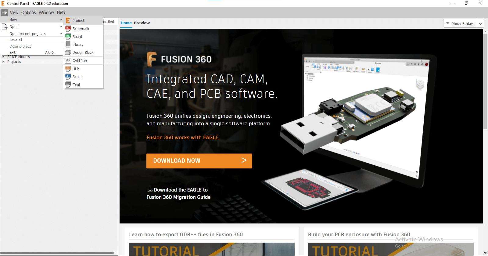
Downloaded Eagle:-
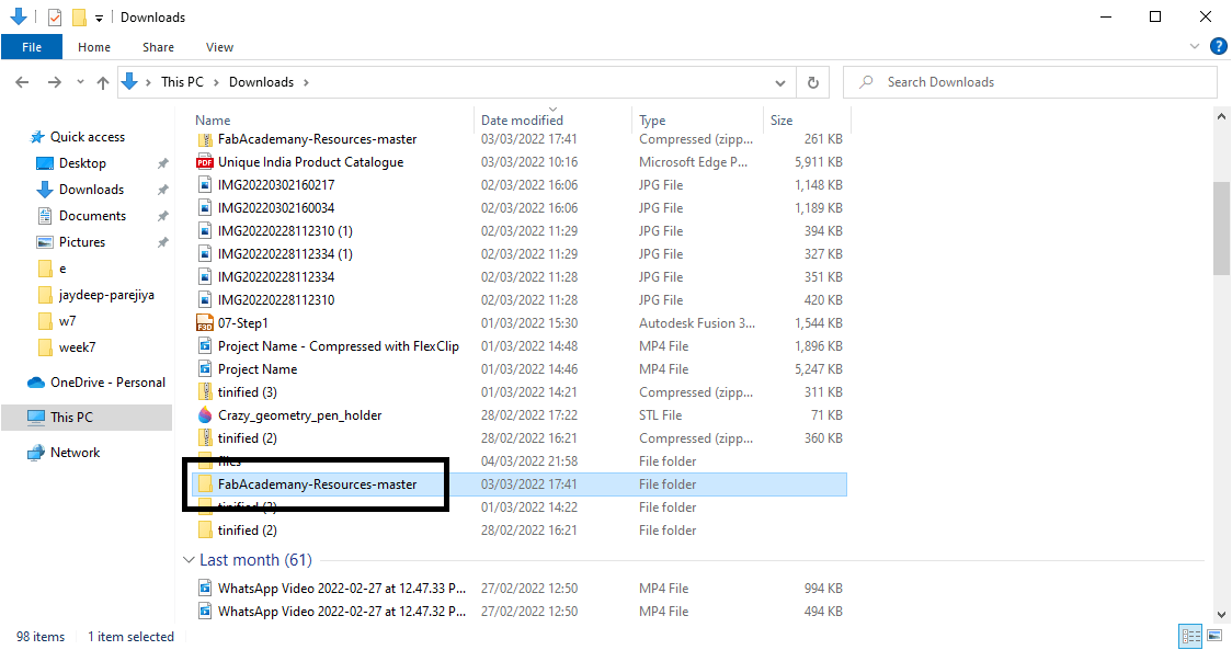
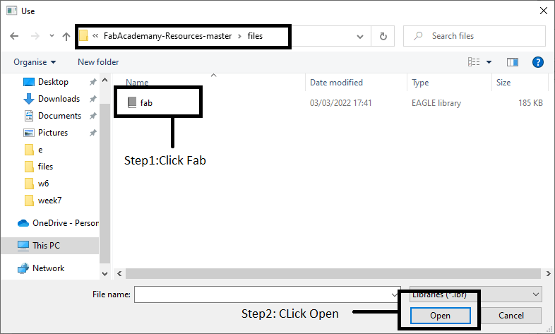
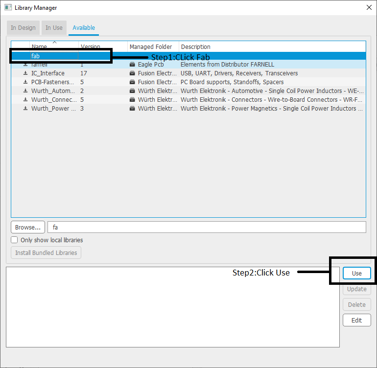
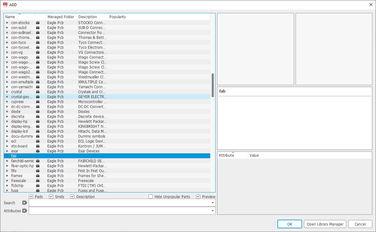
Installed Fab.lbr Library
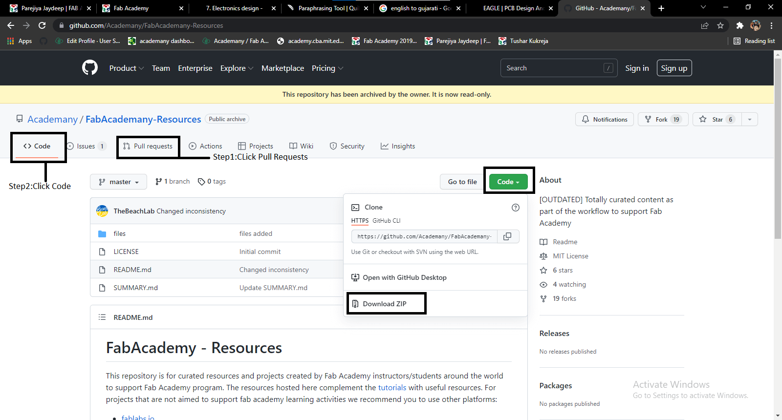
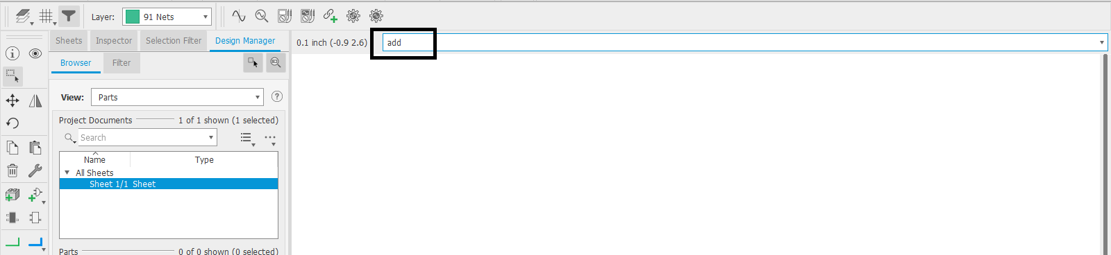
Add Library
Command Line
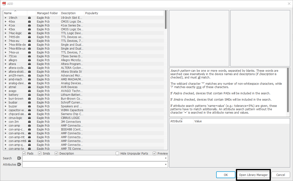
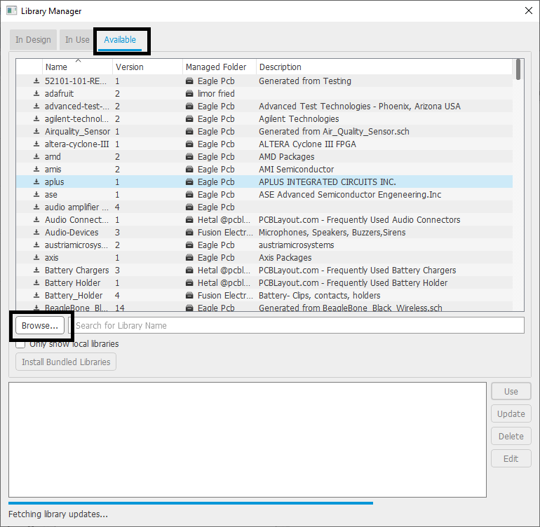
Library Manager:
Created Project:-
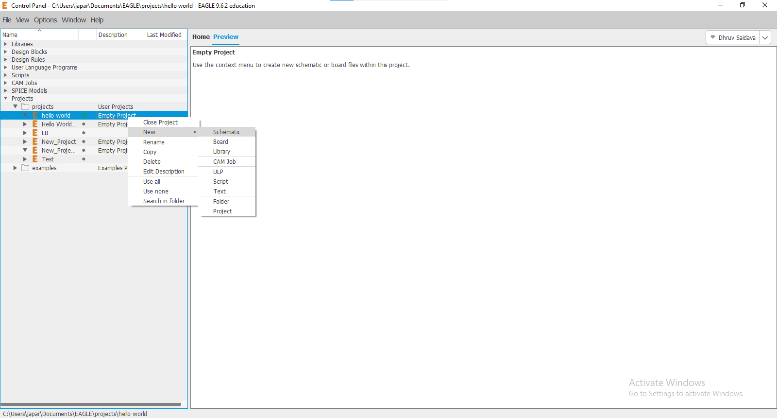
What Is Schematic Design ?
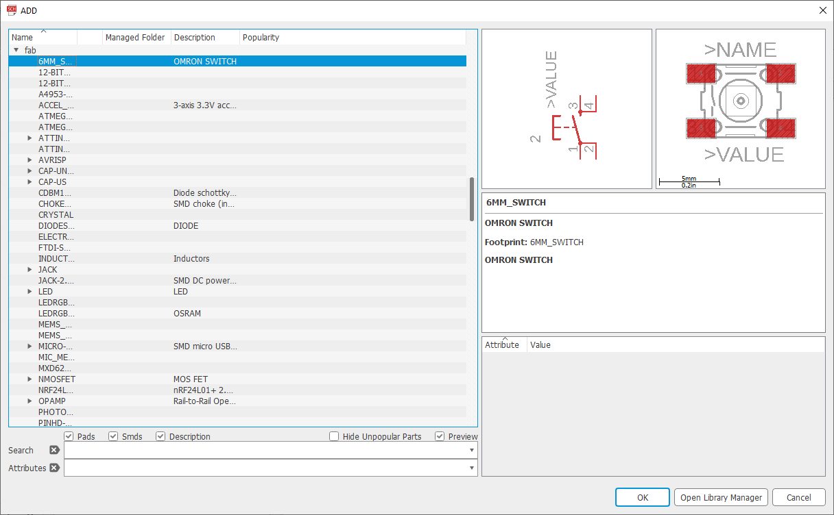
Selected Components
Library Components:
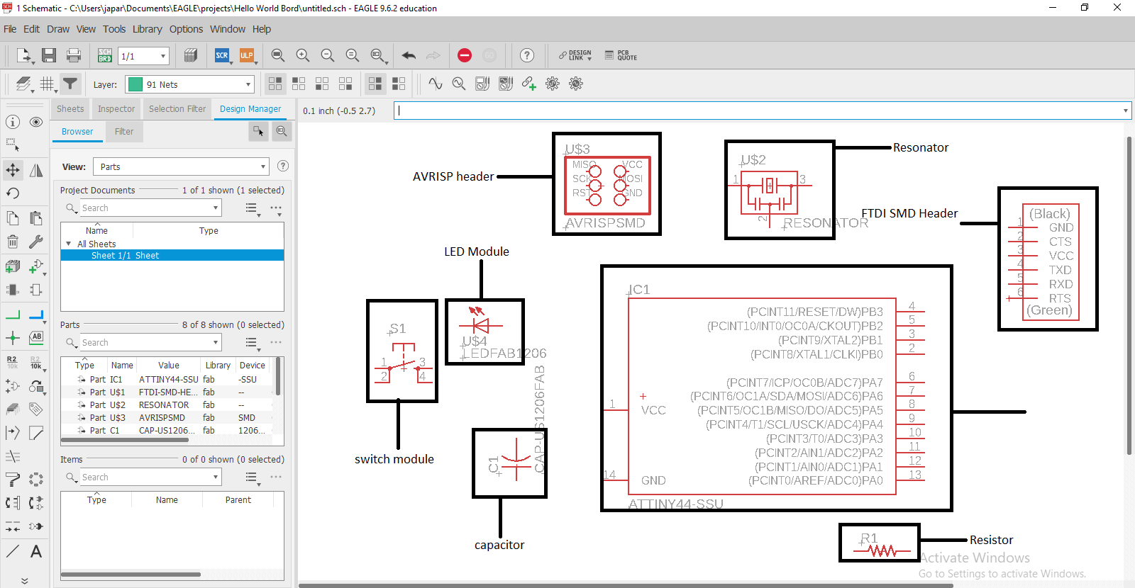
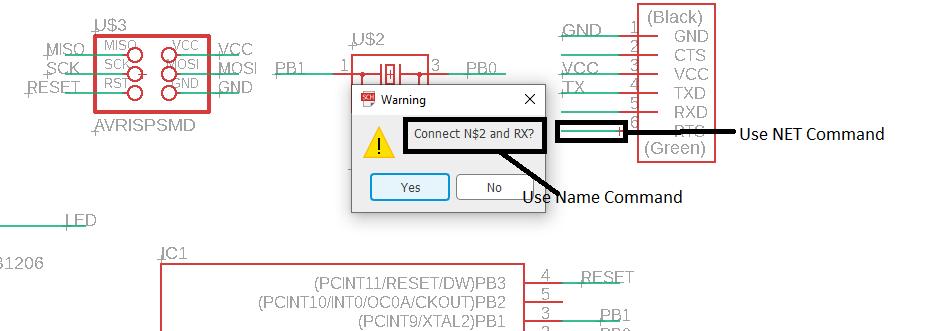
Made Connections:
NET:
Name:
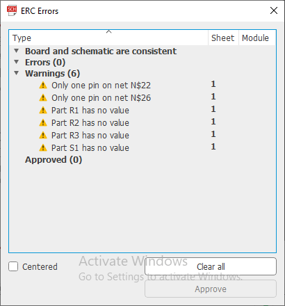
ERC Check:
What is the ERC?
What is the autorouter?
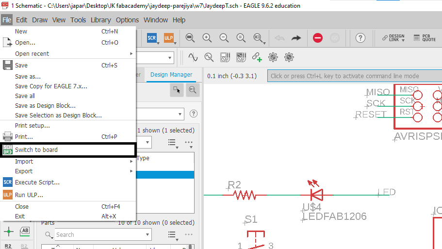
Switch to Board
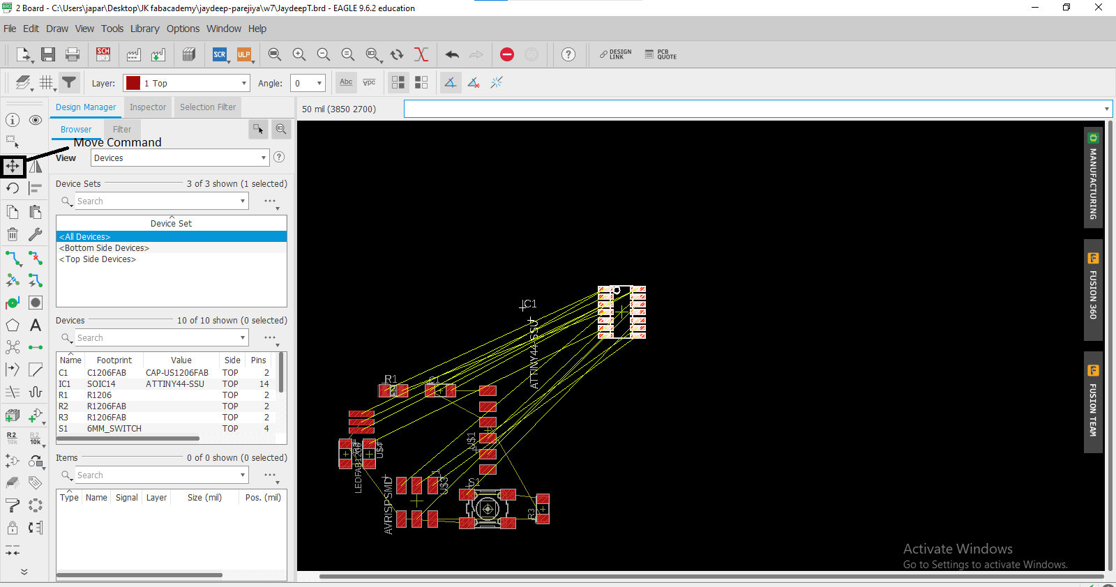
Board Design:
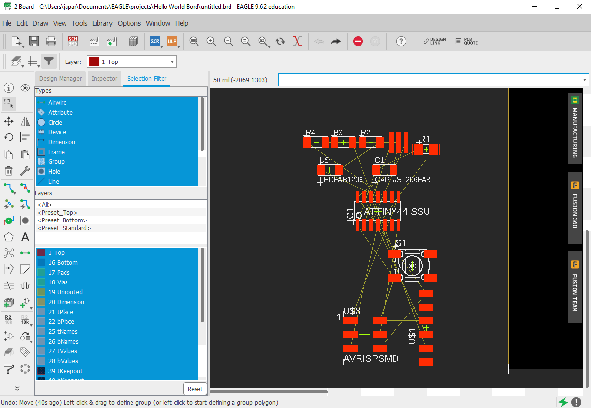
Moved Components:
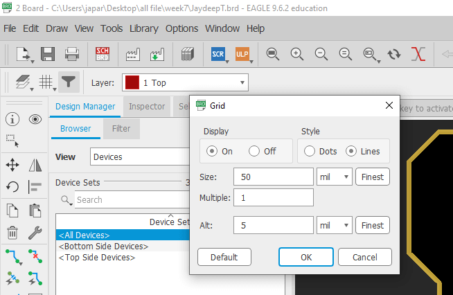
Grid:
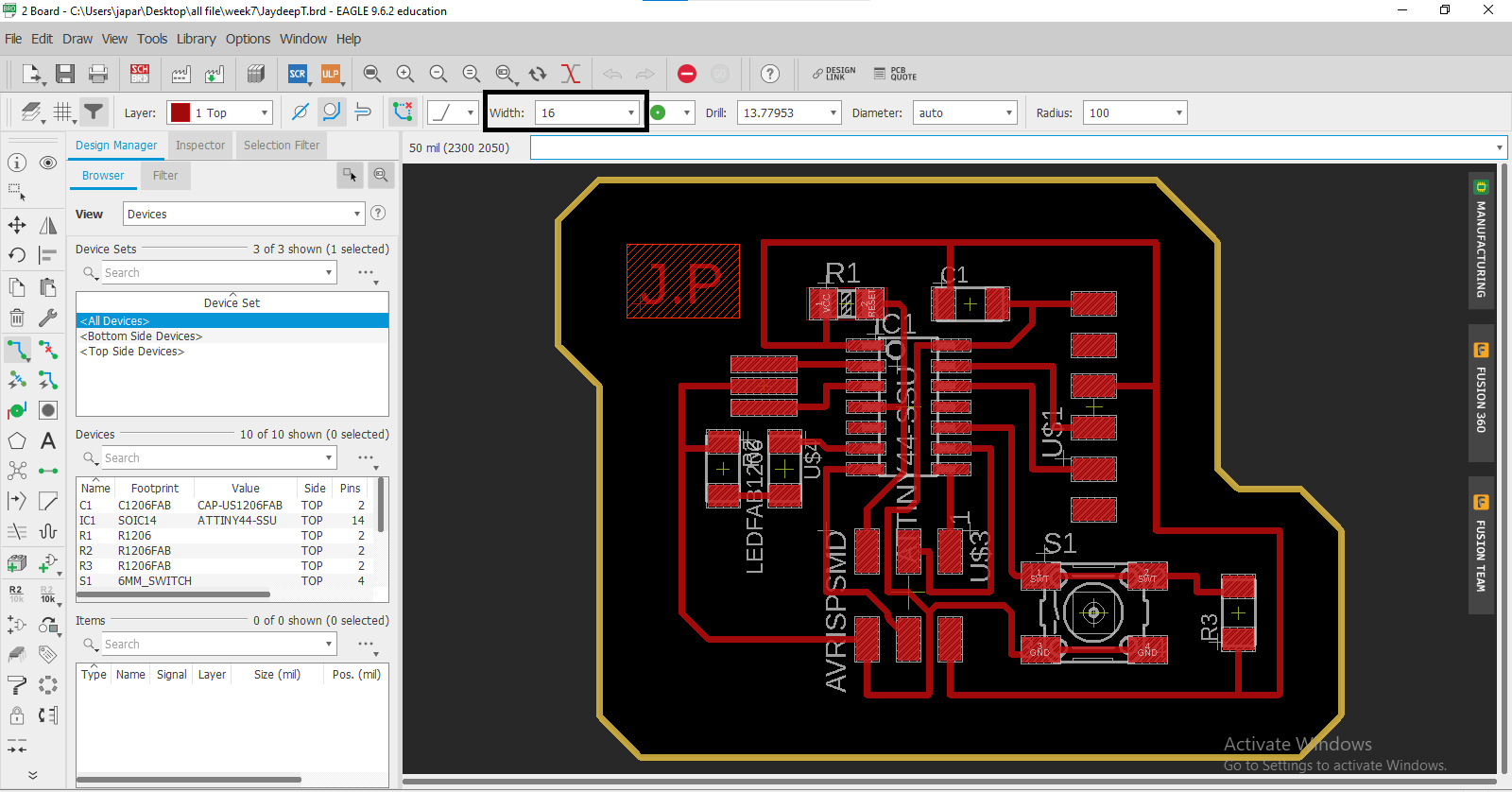
Route Traces:
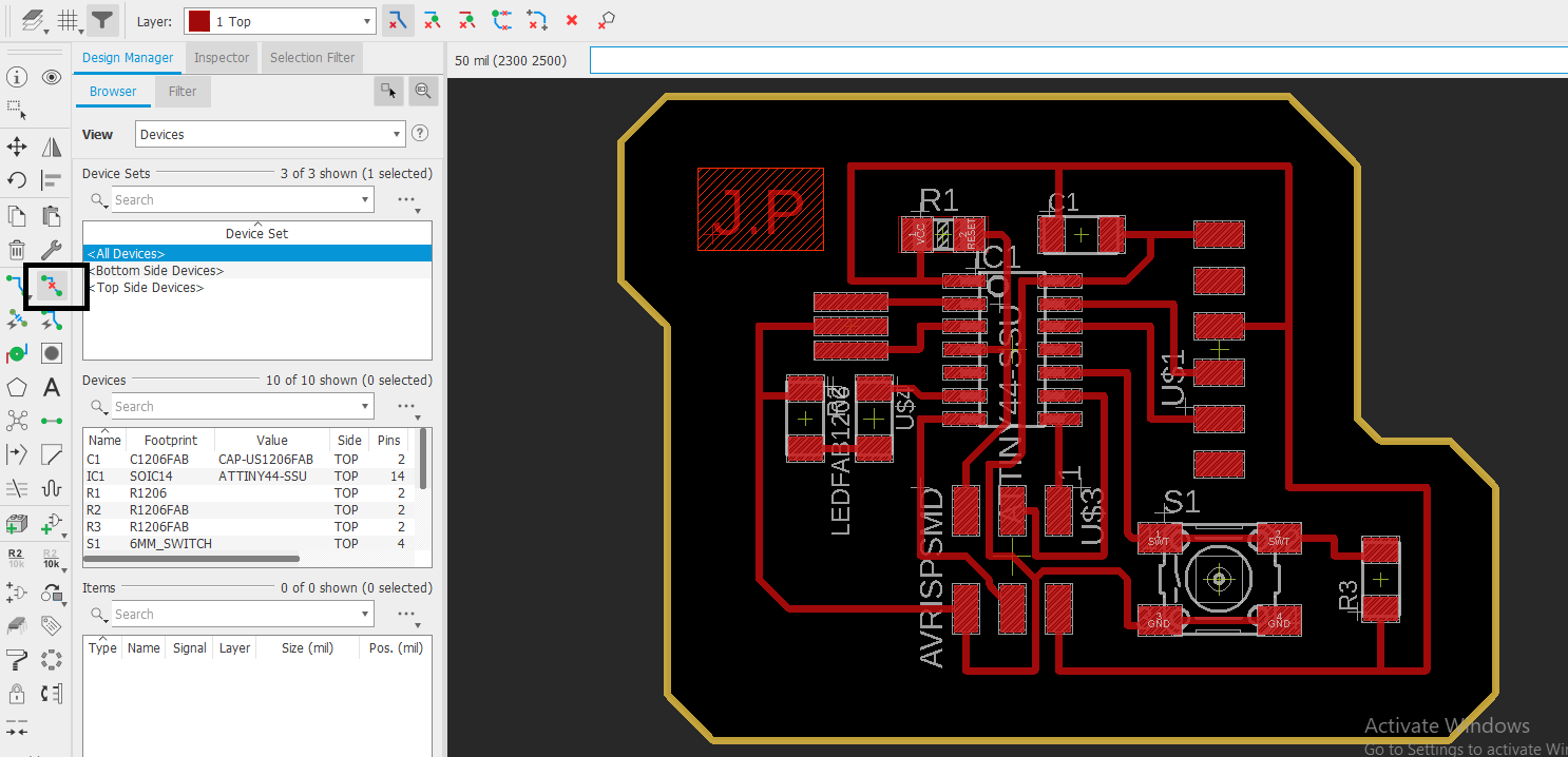
Ripup:
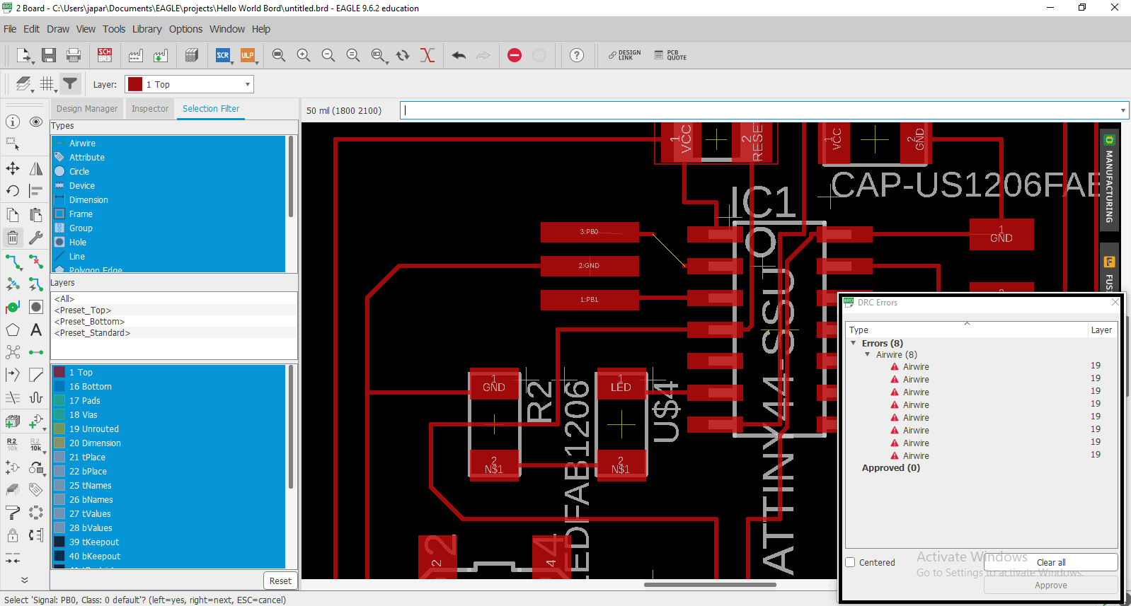
DRC Check:
What is the DRC?
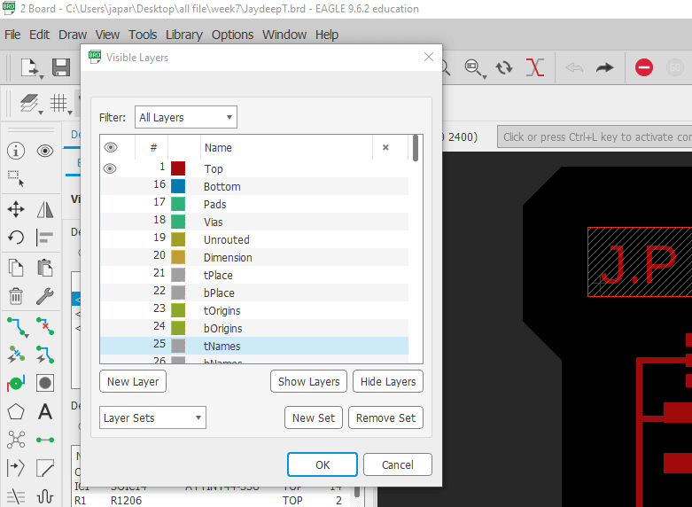
Layers:
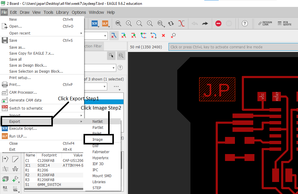
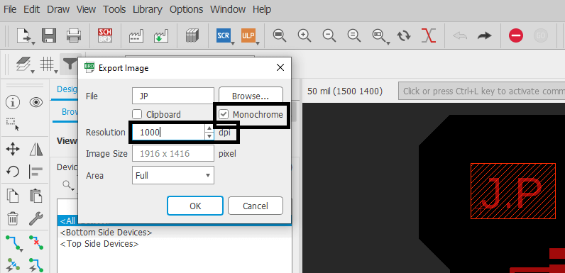
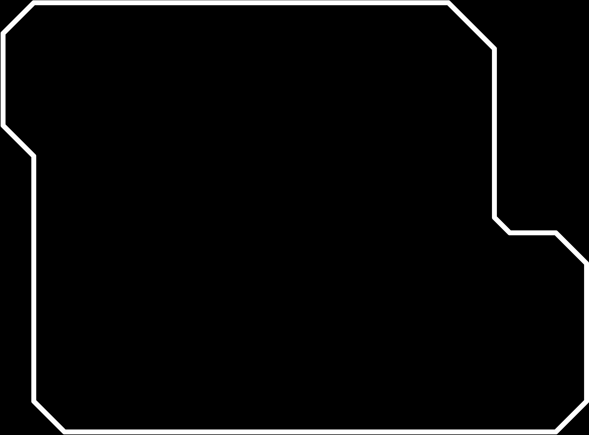
Export File:
Monochrome:
dpi:
Final Board:
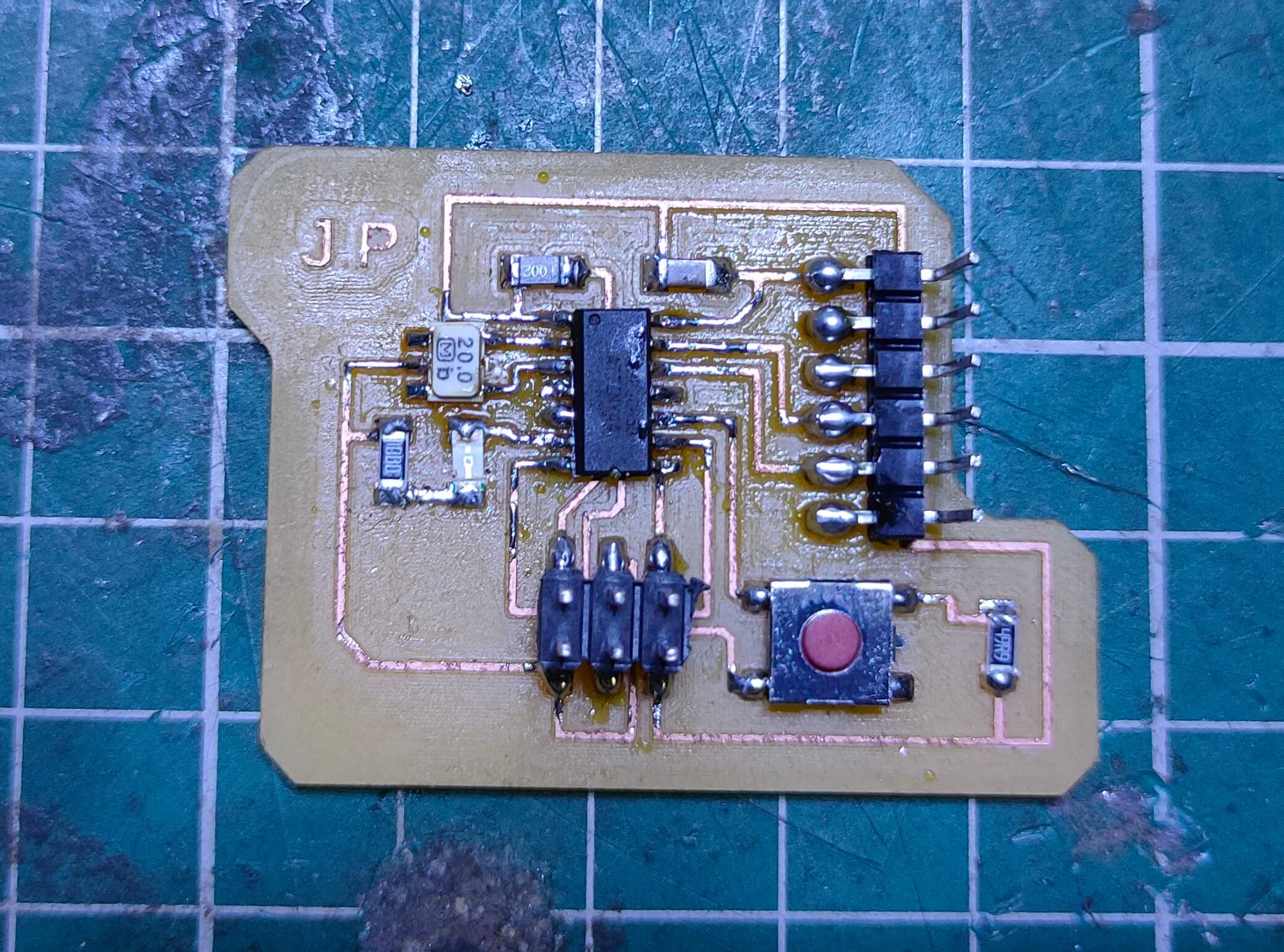
Soldering:-
Components:-The components I soldered to the PCB are listed below:
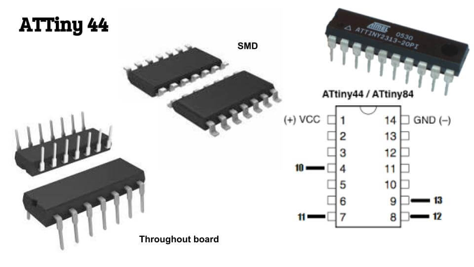
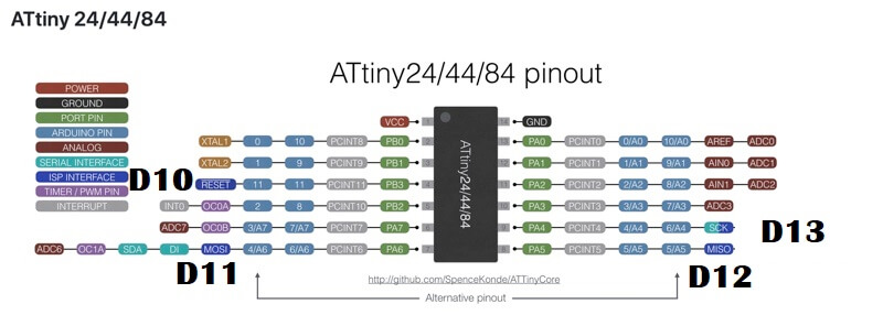
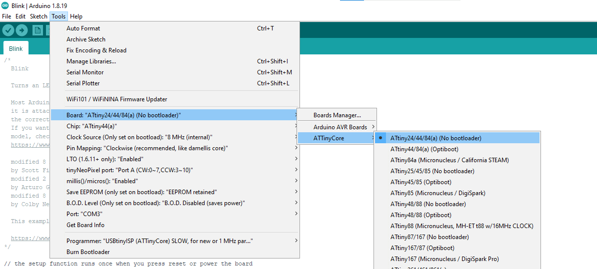
I.C.- Atiny 44
Resistor 1(R1)- 10k ohm
Capacitor- 1 micro Farade
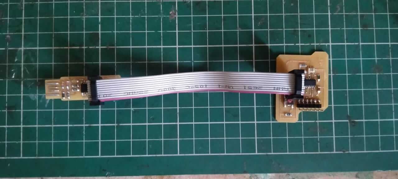
AVRISP
FTDI
Resonator-20 MHz
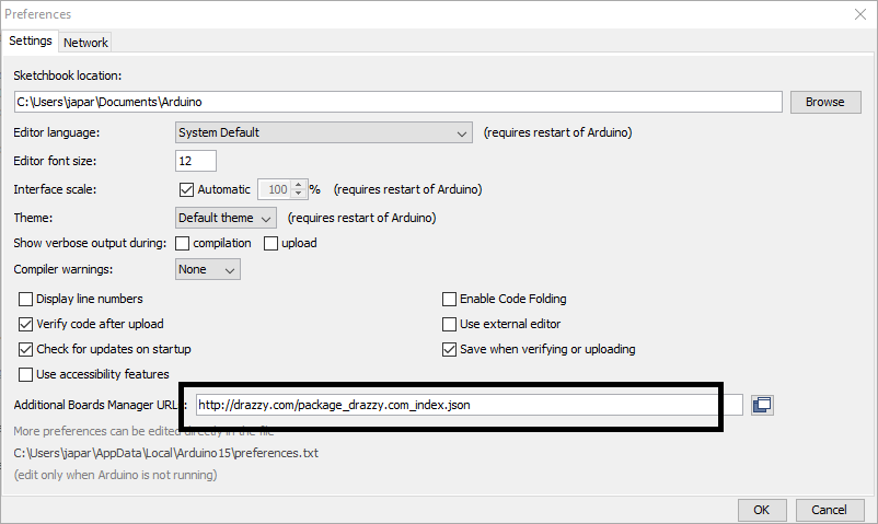
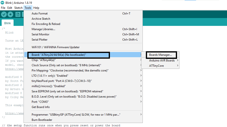
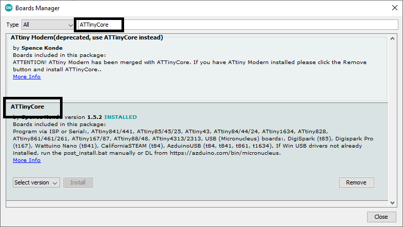
Programming:
http://drazzy.com/package_drazzy.com_index.json
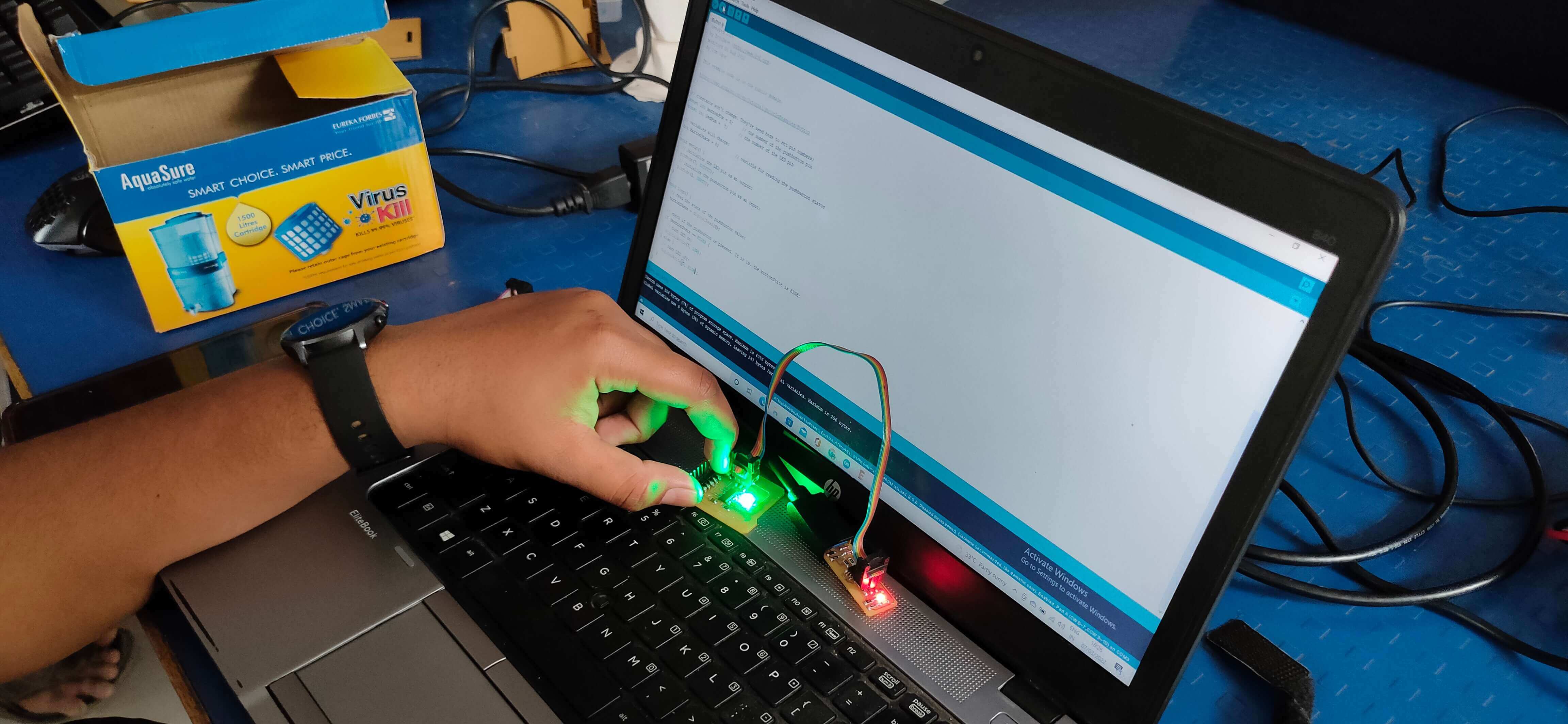
Upload Button Code
Step5: Button And LED Blik Code.
Upload LED Blink Code:-
LED Blik Code:-
Original File All
« 3D Scanning and Printing | Week 06 Computer Controlled Machining | Week 08 »
Safety
Switch by Parejiya
Jaydeep is licensed under CC BY-ND 4.0![]()
![]()
![]()