Design a machine that includes mechanism + actuation + automation + application
Build the mechanical parts and operate it manually
Document the group project and your individual contribution
Machine Design
Actuate and automate your machine
Document the group project and your individual contribution
Our Hero shots and videos:
Concept:
We had a brainstorming session to decide on the machine, it's applications and what kind of
mechanism should the machine have. We had different ideas; however, we thought of making
a machine that can print circuits using materials like conductive clay or ink, etc.
The idea behind using a conductive clay or ink is to make a low-cost material, which is
easily available.
We thought of making the conductive clay using a play dough (made of common flour) that can
be safely
handled by the children. We went through the following video to know more about the
conductive clay.
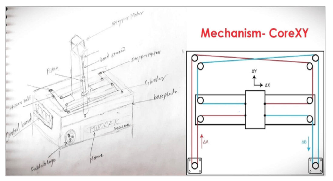
Together as a group, we went through different mechanisms that can be best suited to design
and build a printer. We
concluded to use CoreXY mechanism in our printer. Click here
for Reference and credits.
.
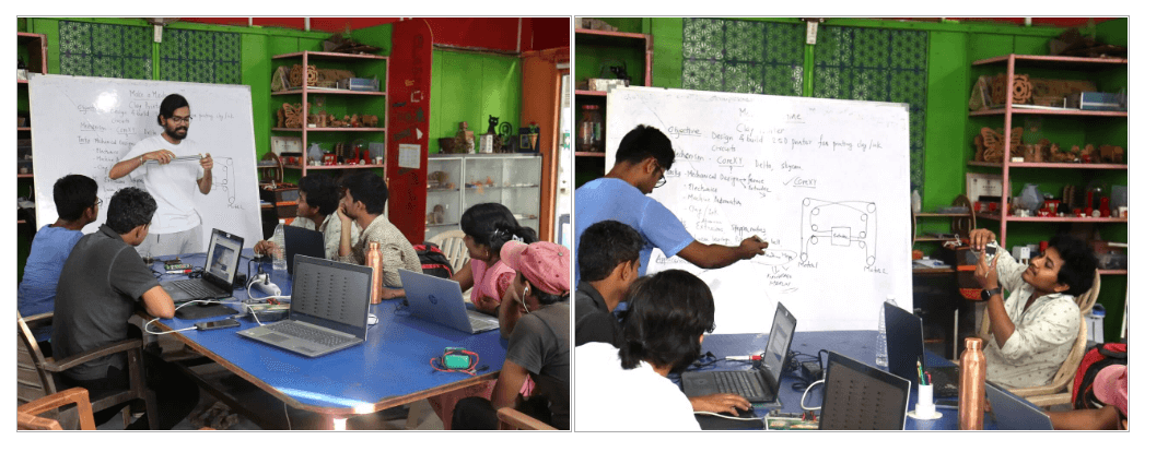
Process Flow:
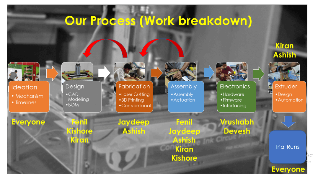
We assigned following tasks amongst ourselves building the machine.
Fenil and Kishore
took the responsibility to design the CoreXY mechanism and gantry of the machine.
Kiran
had the responsibility to design the extruder and prepare the conductive ink.
Jaydeep
took the responsibility of all the fabrication like laser cutting, 3D printing, conventional
cutting and grinding.
Devesh and Vrushabh
had the responsibility of electronics part, which included electronics hardware, firmware
and interfacing.
Ashish
was majorly contributing in to assembly process (entire machine including the extruder
assembly) and preparing the conductive ink.
It was decided that after all the sub-assemblies and ink become ready, everyone will
participate in the assembling and testing of the
machine through test runs followed by the testing of the application (working on the circuit
printed using the conductive ink).
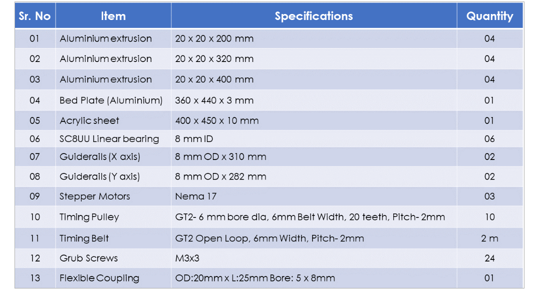
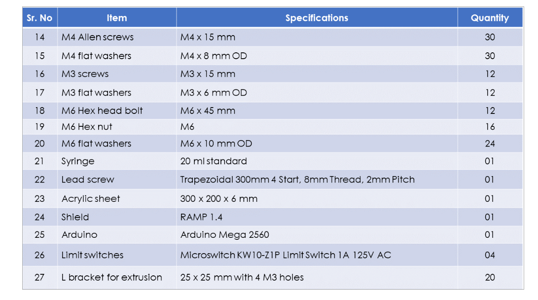
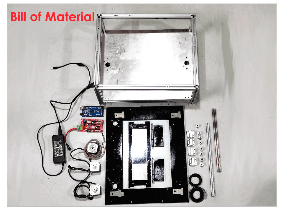
Bill of Material:
Fabrication
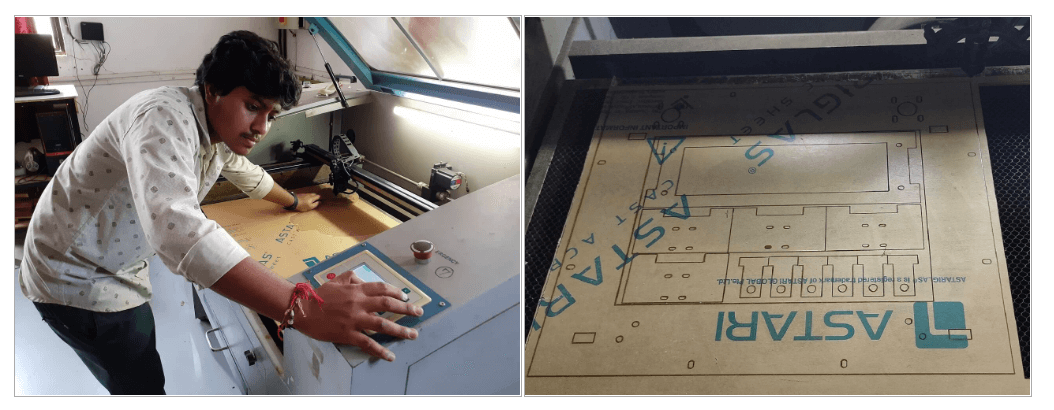
We laser-cut the mainframe and middle frame plates. We also cut the L shape bracket and
T-slot brackets using laser cutting.
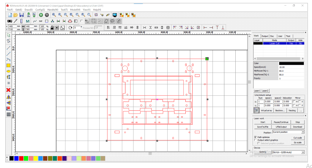
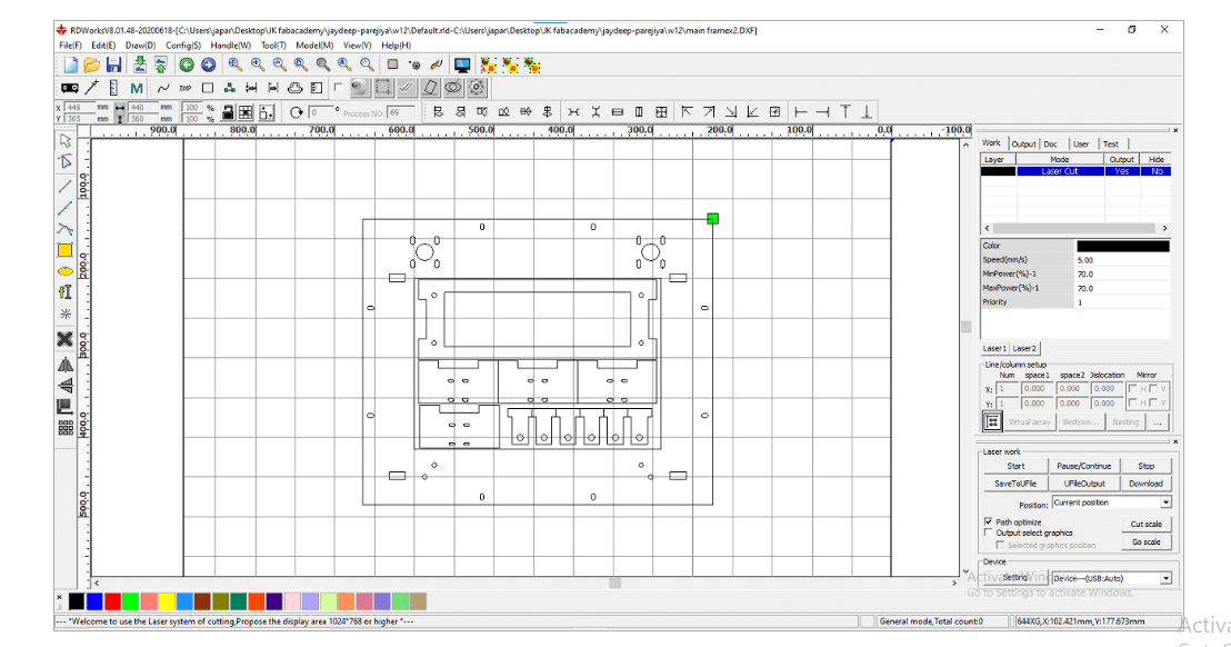
RDworks:- Import design in Rdworks
Laser Cut Cutting Video
3D Printing
We 3D printed the L shape bracket for mounting linear bearings for Y-axis and also T holders
for guide rails after
we found issues in assembly later. We have mentioned the issue later in the document below.
3D Printer Printing Video
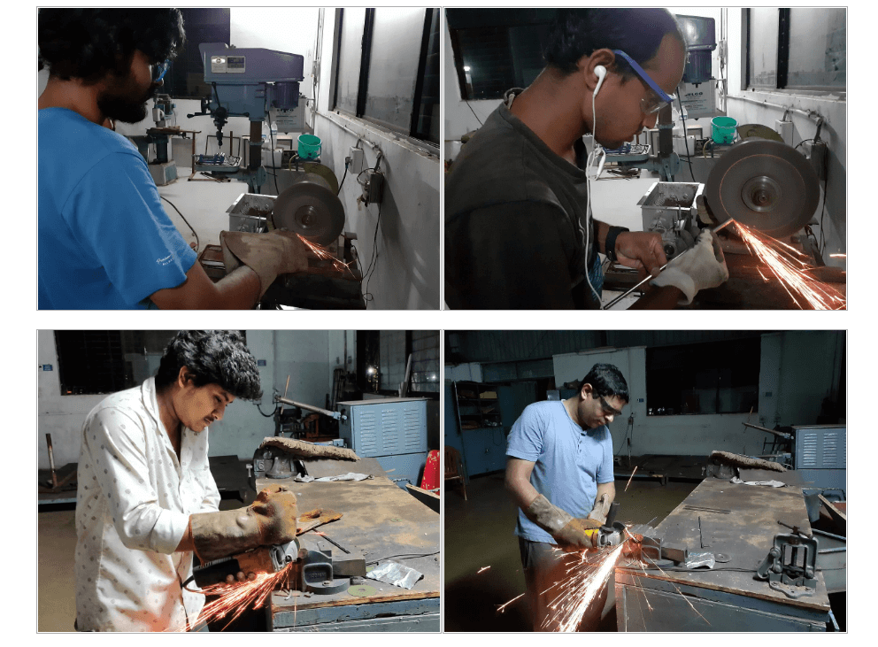
Cutting and Grinding
We needed to cut the guide rail shafts and one aluminum extrusion as per our design, we used
power cutting and grinding tools for these
operations, and we also provided a chamfer on the edges of guide rail shafts.
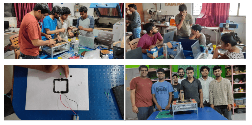
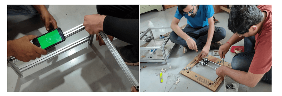
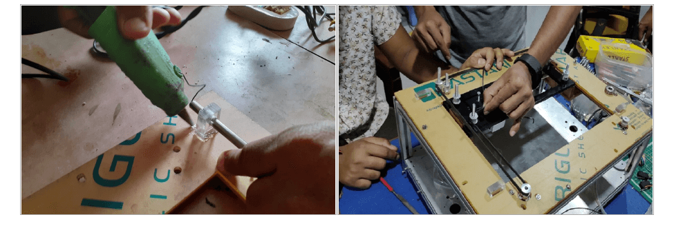
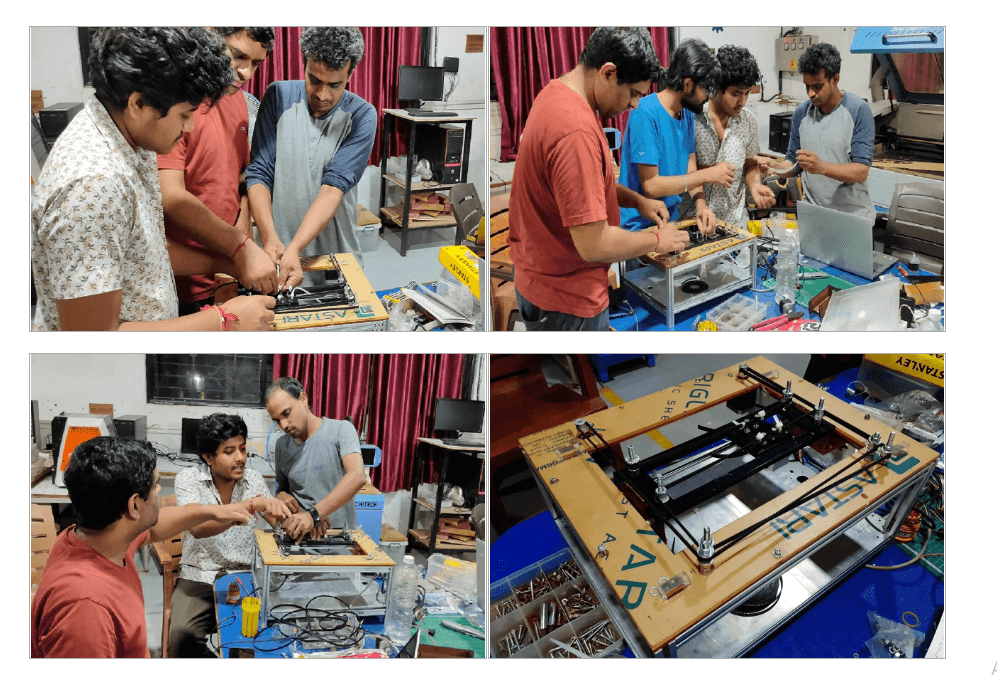
Assembly
Once all the parts were in place (either purchased, laser cut or from our
lab inventory), we started to assemble the machine. Following is a
picture of all the material in place.
Assembly Video
.
We started with building the base frame with the aluminium extrusions we had. We levelled
them as we were assembling them.
We started assembling the main frame sub-assembly and middle frame sub-assembly.
The T-slots we had cut on laser were not cut as per the designed specifications.
So, they were not sitting in place. We fixed them using the glue just to check if
the assembly works. This was not a permanent solution though.
We started assembling all the parts to the assembly, like stepper motors,
pullies, timing belt, hardware, etc.
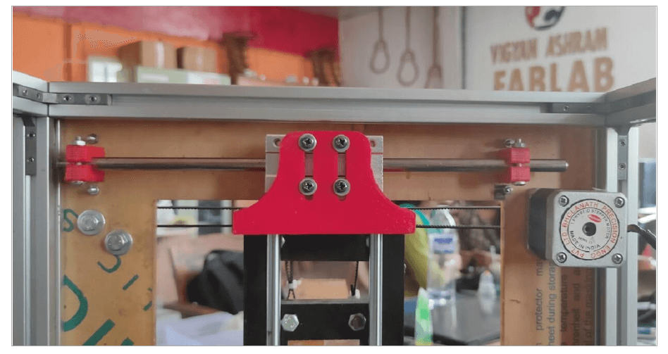
However, during the assembly process, we had fitment and alignment issues with T slot
brackets that hold the guiderails along the Y axis,
L shape bracket that hold the linear bearings. The T-slots cut by laser were not having
proper press-fit and the L-shape bracket was not
at perfect 90 degrees. Apart from that these guiderails had single linear bearing each, so
the movement of the mechanism along the Y axis
was not happening smoothly, it was wobbeling too much.
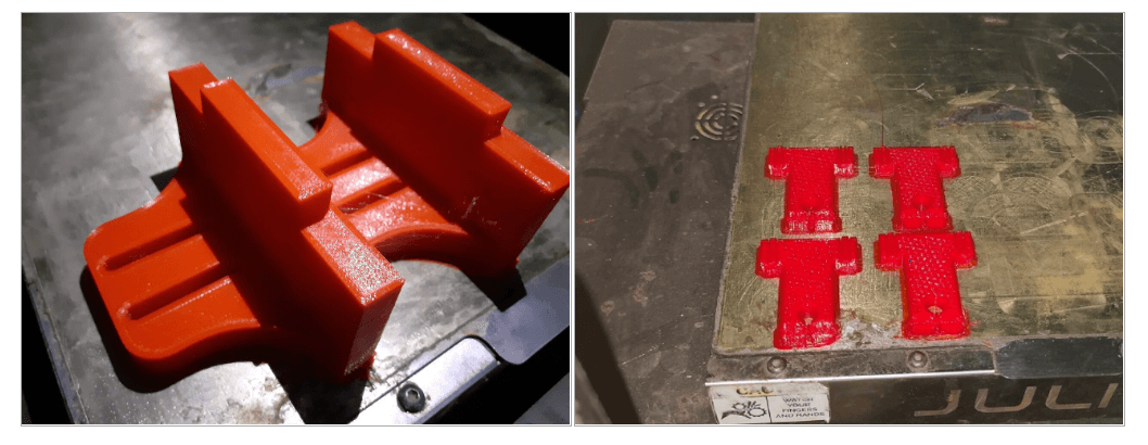
So we decided to go for 3D printing of T brackets for holding guiderails and L bracket for
mounting linear bearings. Also we added an
extra bearing each to the Y-axis guiderails as shown below.
This major hurdle in building our machine was thus removed successfully after
implementing this solutions. The mechanism was working perfect now.
Actuation
After we replaced these parts and adding extra bearings, we re-assembled all the
parts again and we were able successfully actuate the mechanism as shown in the
video below. It works pefrectly fine on all 6 different movements.