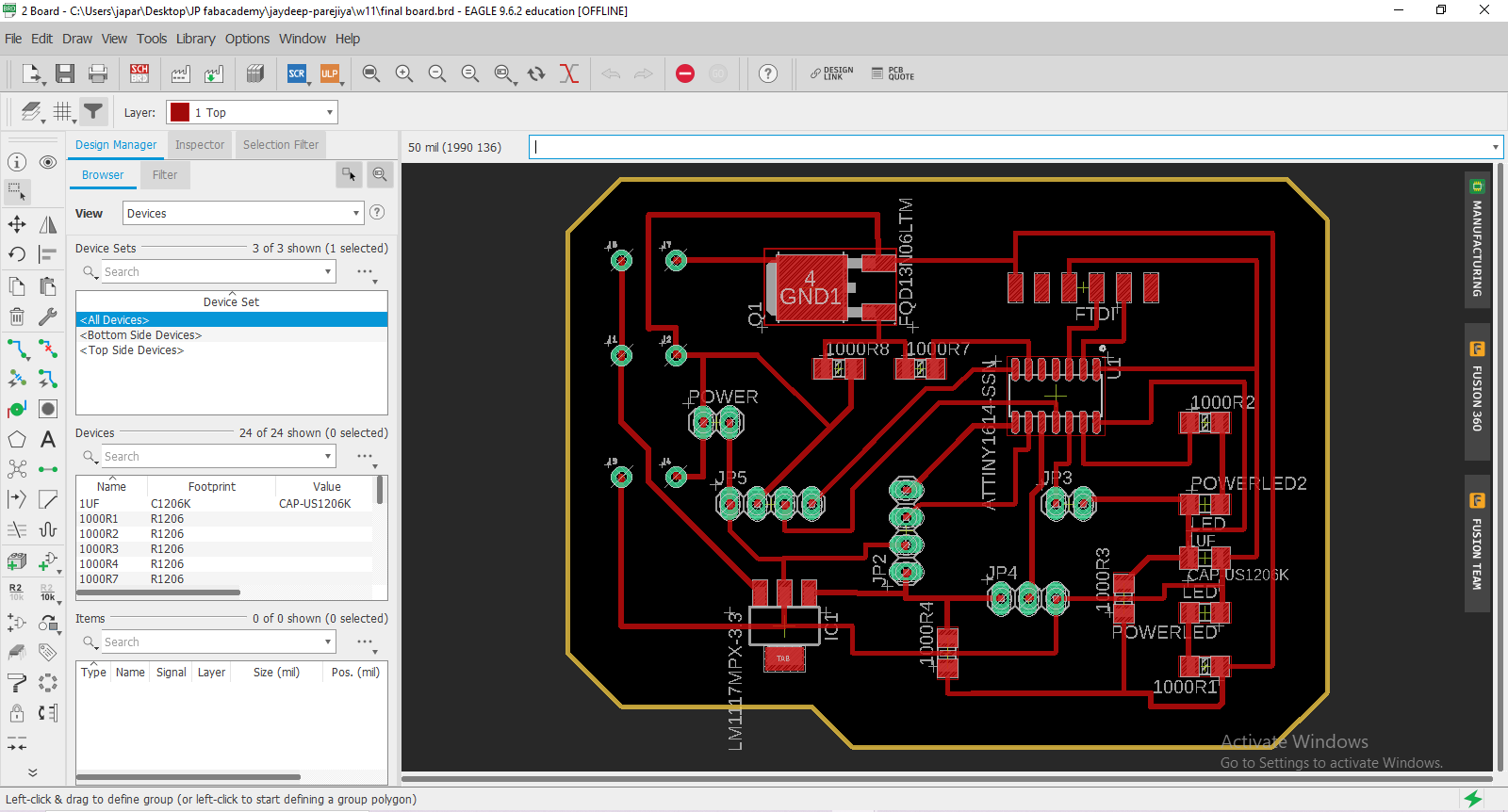
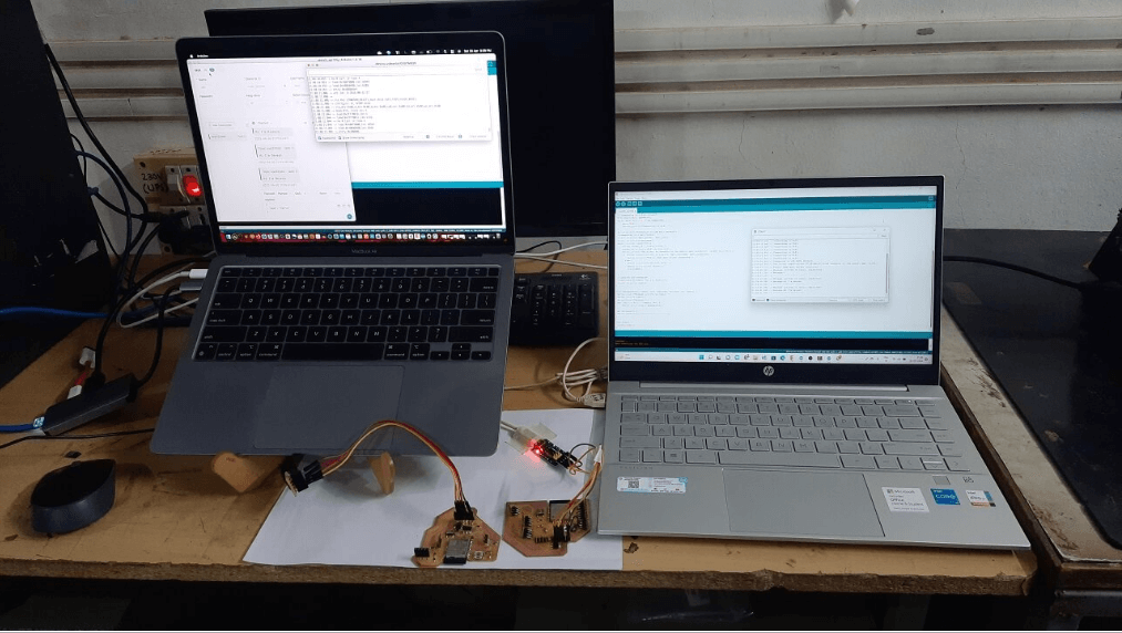
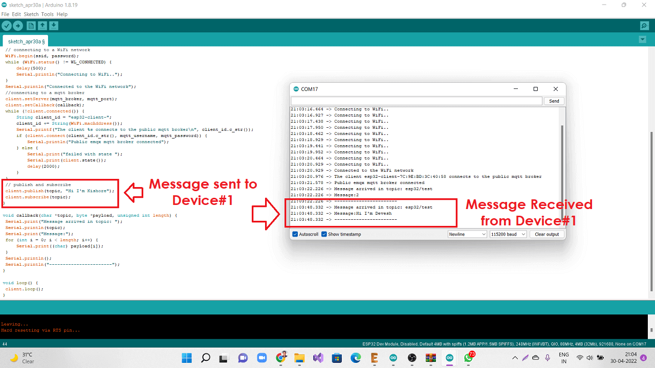
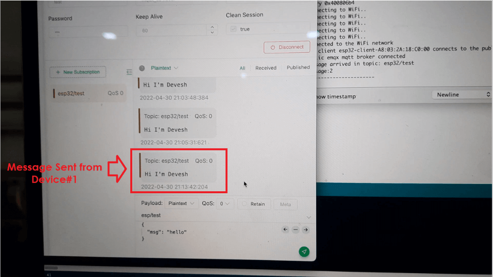
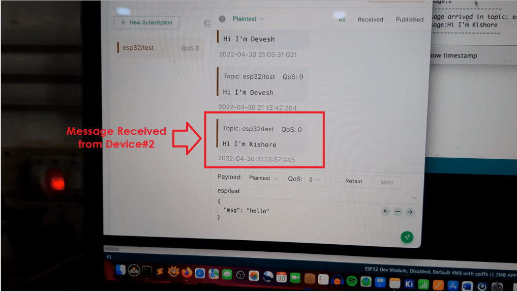
For the purpose of this group assignment, we established communication between two of our
project
boards having ESP32-Wroom microcontroller and were able to send messages between the boards
as shown below.
design, build, and connect wired or wireless node(s)
with network or bus addresses
Networking
It is the linking of various devices via multiple channels for data or media transmission.
These data are
transmitted by cable, wires, or fiber optic cables, as well as wireless media such as Wi-Fi.
Communication
Communication refers to the transfer of information or commands from one board to another.
The types of communication are as follows.
Parallel Communication
Parallel interfaces allow several bits to be transferred at the same time. They frequently
necessitate data buses, which transfer data over eight, sixteen,
or more wires. The data is sent in massive, crashing waves of 1s and 0s. It sends out
numerous bits of info at once. They necessitate data buses that transmit
across eight, sixteen, or more wires.
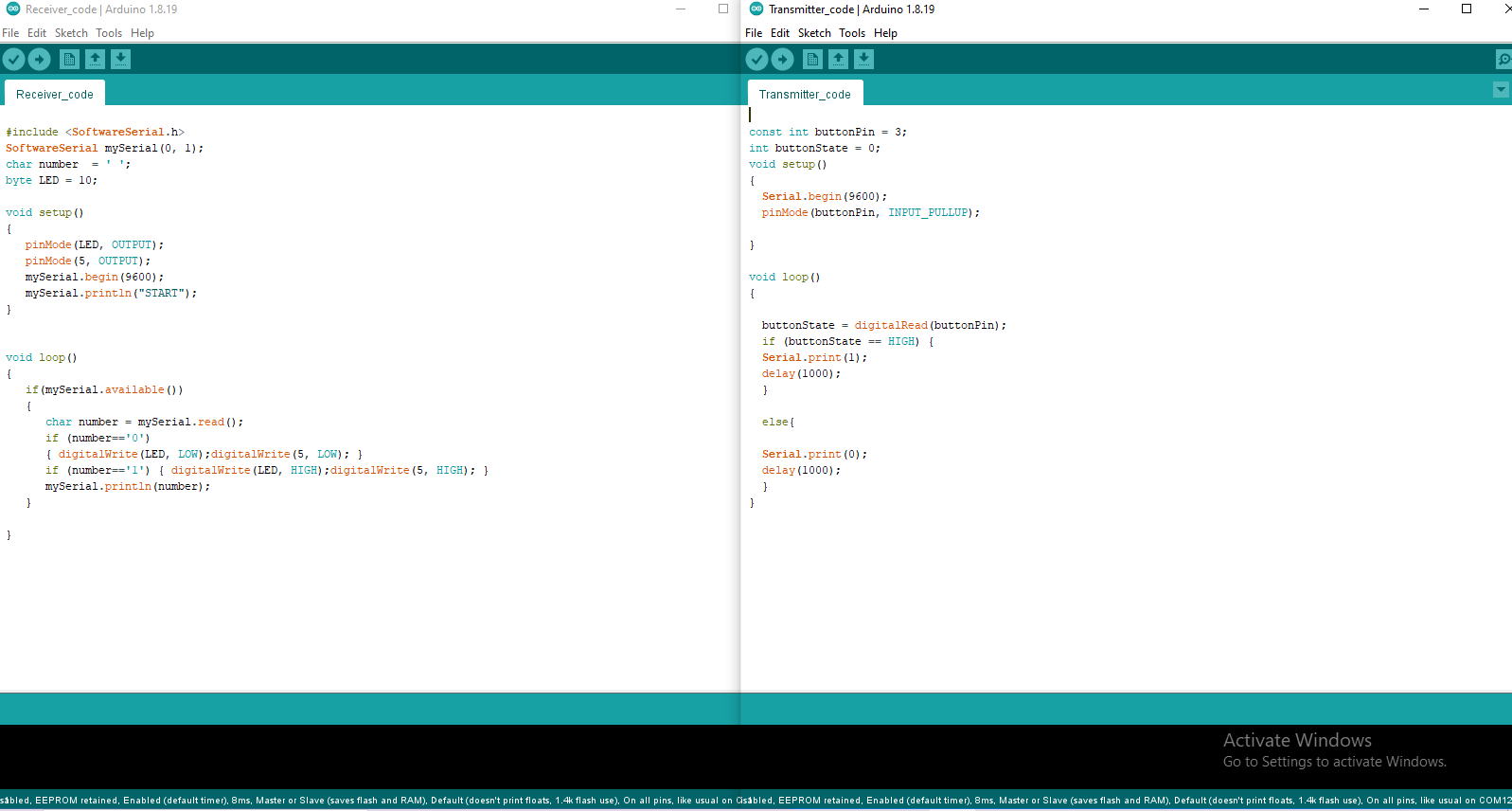
Serial Communication
Serial interfaces send data one bit at a time across a wire. These interfaces can work with
as few as one wire, but rarely more than four. However,
this kind of communication is slower than Parallel, but it is more reliable.
Synchronous serial interface
The sender and receiver share the same clock in synchronous serial interface.
This results in a more straightforward and typically faster serial transfer, but
it also necessitates the use of at least one additional cable between the communication
devices.
SPI and I2C, for example.
Asynchronous serial interface
Data is sent asynchronously, without the use of an external clock signal. This type of
transmission is ideal for reducing the number of
cables and I/O pins required. The Rx and TX pins on MCUs are used to implement this
strategy. This mode connects devices such as GSM, GPS, and Xbee.
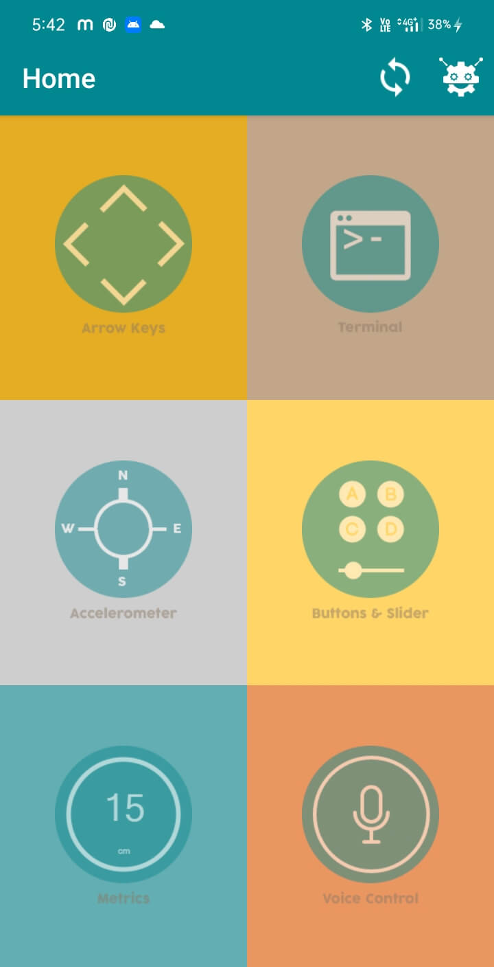
It is used for many applications like wireless headset, game controllers, wireless mouse,
wireless keyboard and many more consumer applications.
It has range up to 100m which depends upon transmitter and receiver, atmosphere, geographic
& urban conditions.
It is IEEE 802.15.1 standardized protocol, through which one can build wireless Personal
Area Network (PAN). It uses frequency-hopping spread spectrum (FHSS) radio technology to
send data over air.
It uses serial communication to communicate with devices. It communicates with
microcontroller using serial port (USART).
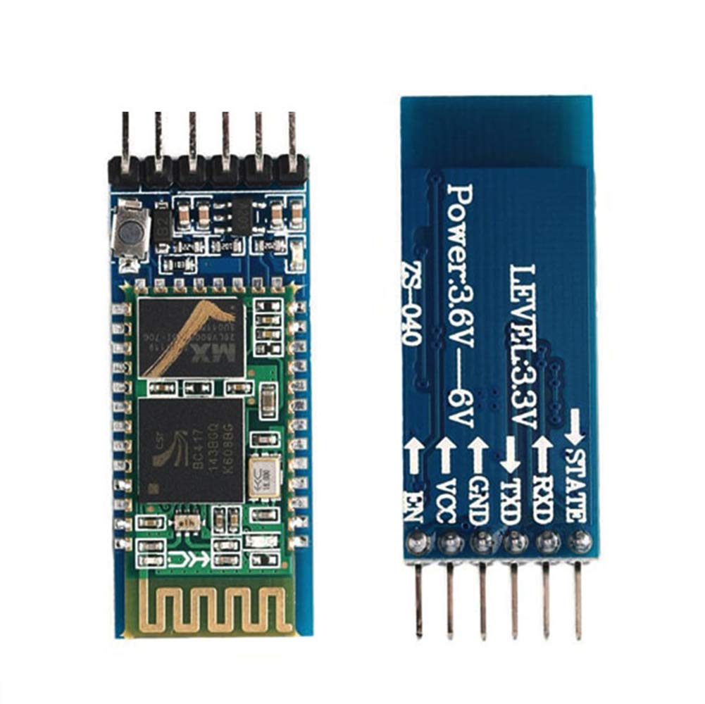
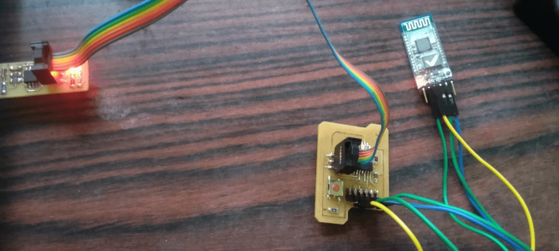
HC-05 Bluetooth Module
HC-05 is a Bluetooth module which is designed for wireless comunication. This module can be
used in a master or slave configuration.
Bluetooth serial modules allow all serial enabled devices to communicate with each other
using Bluetooth.
It has 6 pins,
Key/EN:
It is used to bring Bluetooth module in AT commands mode. If Key/EN pin is set to high,
this module will work in command mode. Otherwise by default it is in data mode.
The default baud rate of HC-05 in command mode is 38400bps and 9600 in data mode.
HC-05 module has two modes,
Data mode
Exchange of data between devices.
Command mode:
It uses AT commands which are used to change setting of HC-05.
To send these commands to module serial (USART) port is used.
VCC:
Connect 5 V or 3.3 V to this Pin.
GND
Ground Pin of module
TXD
Transmit Serial data (wirelessly received data by Bluetooth module transmitted out serially
on TXD pin)
RXD
Receive data serially (received data will be transmitted wirelessly by Bluetooth module).
State:
It tells whether module is connected or not.
HC-05 module Information
HC-05 has red LED which indicates connection status, whether the Bluetooth is
connected or not. Before connecting to HC-05 module this red LED blinks
continuously in a periodic manner. When it gets connected to any other
Bluetooth device, its blinking slows down to two seconds.
This module works on 3.3 V. We can connect 5V supply voltage as well
since the module has on board 5 to 3.3 V regulator.
As HC-05 Bluetooth module has 3.3 V level for RX/TX and microcontroller
can detect 3.3 V level, so, no need to shift transmit level of HC-05 module.
But we need to shift the transmit voltage level from microcontroller to RX of HC-05 module.
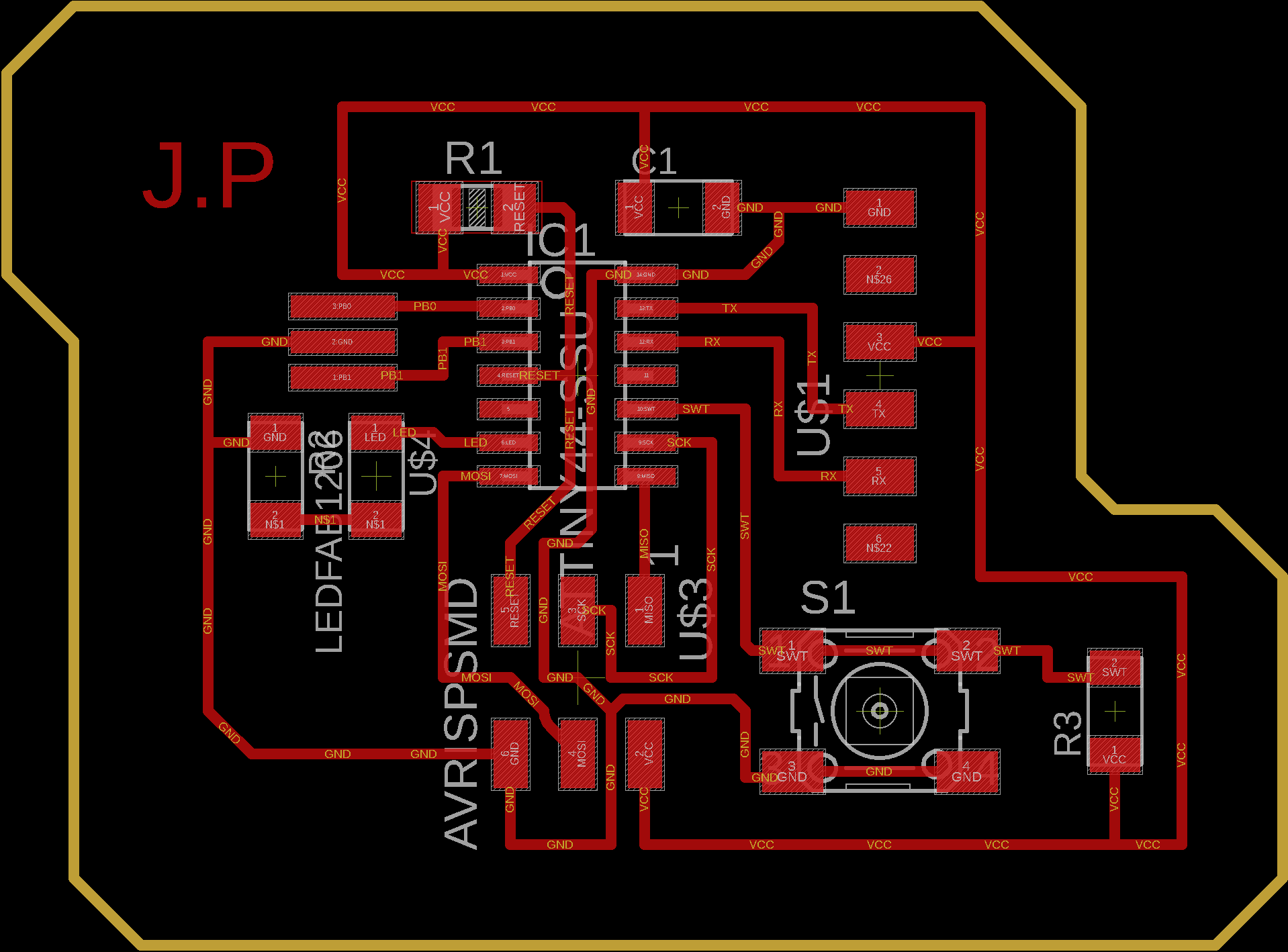
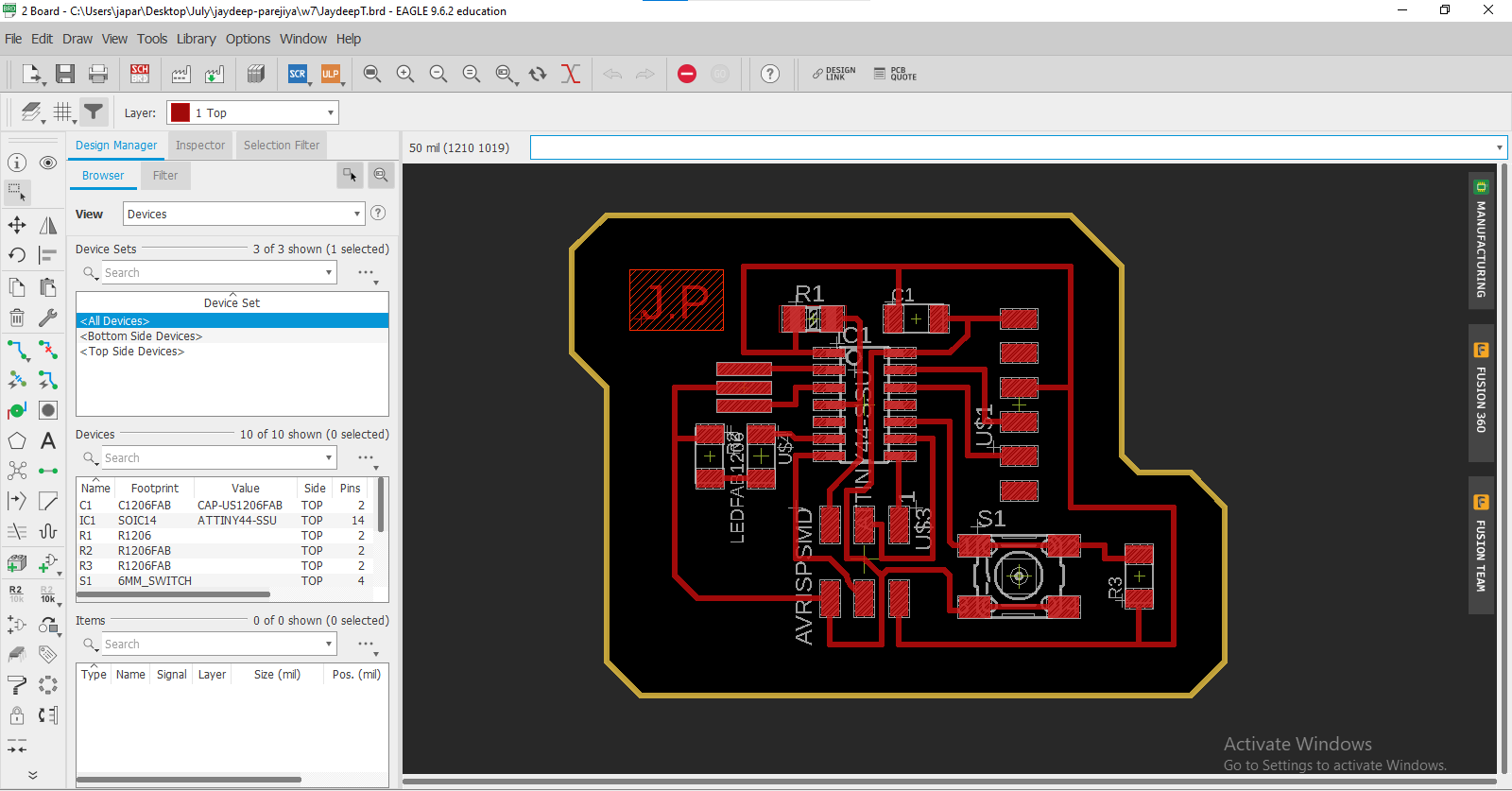
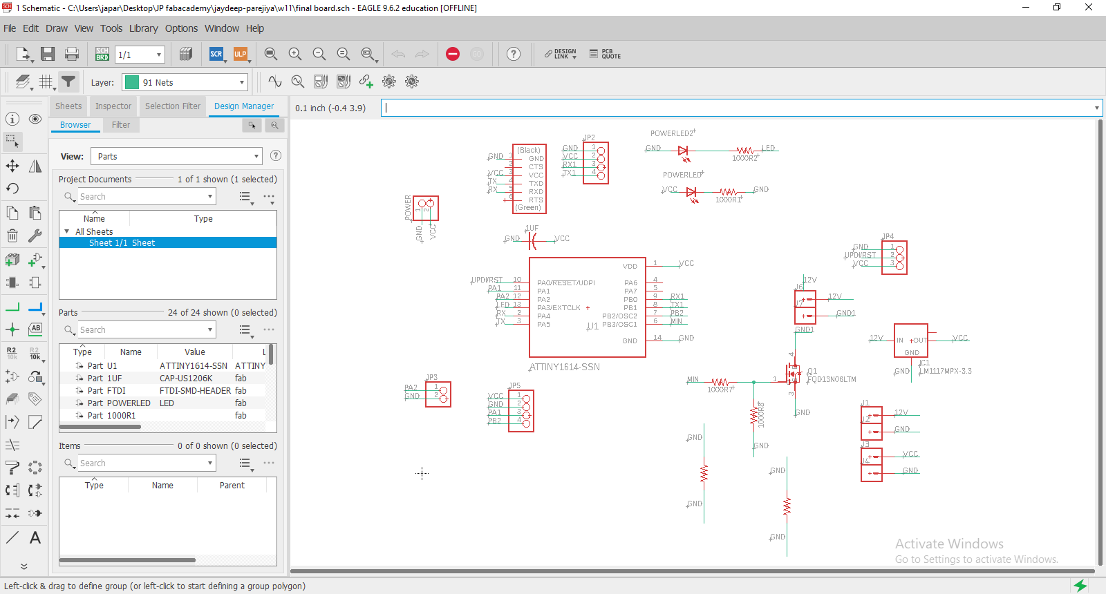
Then when it didn't happen on Attiny 44, I used attiny1614 IC.
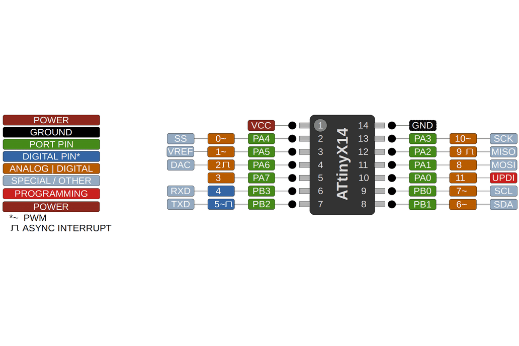
What is the attiny1614.
The ATtiny1614 is a 14-pin microcontroller with an 8-bit AVR® processor with
a hardware multiplier that runs at up to 20 MHz and has 16 KB Flash, 2 KB SRAM,
and 128B of EEPROM.