An input device, such as a Micro Controller, is a piece of equipment or a component that
provides data
and control signals to an information processing system. Sensors, cameras, and other input
devices are
examples of input devices.
Analog Sensors
Different types of analogue sensors create a continuous analogue output signal and are
referred to as
analogue sensors. The analogue sensors give a continuous output signal that is proportional
to the measurand.
Analog sensors come in a variety of shapes and sizes; practical examples include
accelerometers, pressure sensors,
light sensors, sound sensors, temperature sensors, and so on.
Accelerometers
Accelerometers are analogue sensors that detect changes in position, velocity, direction,
shock, vibration,
and tilt via sensing motion. Based on the range of configurations and sensitivities, these
analogue accelerometers
are divided into distinct categories.
Light Sensors
Light Dependent Resistor
Light sensors are analogue sensors that are used to detect the amount of light striking the
sensors.
These analogue light sensors are further divided into photo-resistor, Cadmium Sulfide (CdS),
and photocell varieties. The light dependent resistor (LDR) can be used as an analogue light
sensor to turn on and off loads automatically based on the amount of daylight falling on it.
The LDR's resistance increases with lower light levels and diminishes with higher light
levels.
Sound Sensors
Analog Sound Sensor
Sound sensors are analogue sensors that are used to detect sound levels. For sound level
sensing,
these analogue sound sensors convert the amplitude of the acoustic volume of the sound into
an electrical
voltage. This approach necessitates some circuitry and makes use of a microcontroller and a
microphone
to generate an analogue output signal.
Pressure Sensor
Piezoelectric Sensor
Analog pressure sensors are analogue sensors that are used to measure the amount of pressure
applied to a sensor.
The amount of applied pressure is proportional to the analogue output signal produced by the
pressure sensor. These
pressure sensors are utilised in a variety of applications, including piezoelectric plates
and piezoelectric sensors
for electric charge generation. These piezoelectric sensors are a form of pressure sensor
that may create an analogue
output voltage signal proportional to the applied pressure.
Analog Temperature Sensor
Temperature sensors, both digital and analogue, are commonly accessible. Thermistors are the
most common analogue temperature sensors.
Thermistors come in a variety of shapes and sizes, and they're utilised for a variety of
purposes. Thermistor is a temperature-sensitive
resistor used to monitor temperature changes. The electrical resistance of the thermistor
increases as the temperature rises. Similarly,
as the temperature drops, so does the resistance. It can be found in a number of temperature
sensor applications.
A thermistor-based temperature control system is an example of an analogue temperature
sensor in action. This project is used to keep a room
at a consistent temperature. A temperature control system block diagram includes a bulb
(which depicts a cooler), a temperature sensor or thermistor,
and a relay.
Digital Sensors
Digital sensors are electronic or electrochemical sensors that perform data conversion and
transmission in a digital format. These digital sensors
are replacing analogue sensors because they can overcome analogue sensors' shortcomings. The
digital sensor is made up of three main parts: the sensor,
the cable, and the transmitter. The signal measured by digital sensors is instantly
transformed to a digital signal output within the digital sensor.
And this digital signal is digitally delivered through cable. Different types of digital
sensors exist to address the drawbacks of analogue sensors.
Digital Accelerometers
Pulse-width modulation is the way of generating variable frequency square wave output from a
digital accelerometer. The pulse width modulated accelerometer
takes data at a constant rate, usually 1000 Hz (but this can be configured by a user based
on the IC used). The acceleration value is proportional to the
output PWM signal, pulse width, or duty cycle.
Digital Temperature Sensor
igital Temperature Sensor DS1620
The DS1620 is a digital temperature sensor that offers 9-bit temperature data for devices.
With its three thermal alarm outputs, it functions as a thermostat.
THIGH is driven high if the device's temperature is more than or equal to the user-defined
temperature TH. The TLOW is driven high if the device's temperature
is less than or equal to the user-defined temperature TL. The TCOM is driven high if the
device's temperature exceeds TH and remains high until it falls below
that of TL.
Objectives of the Group Assignment:
Probe an input device's analog levels and digital signals
Input Device that we probed for it's analog and digital signals:
IR sensor
Potentiometer
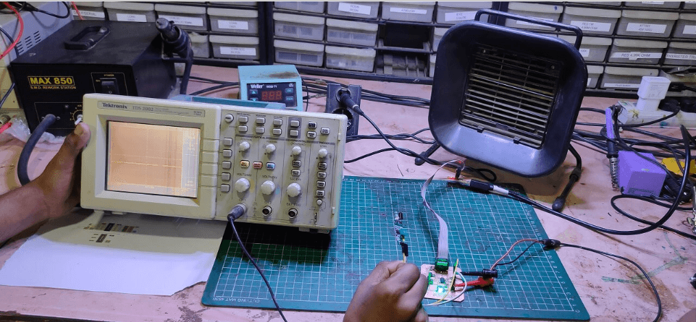
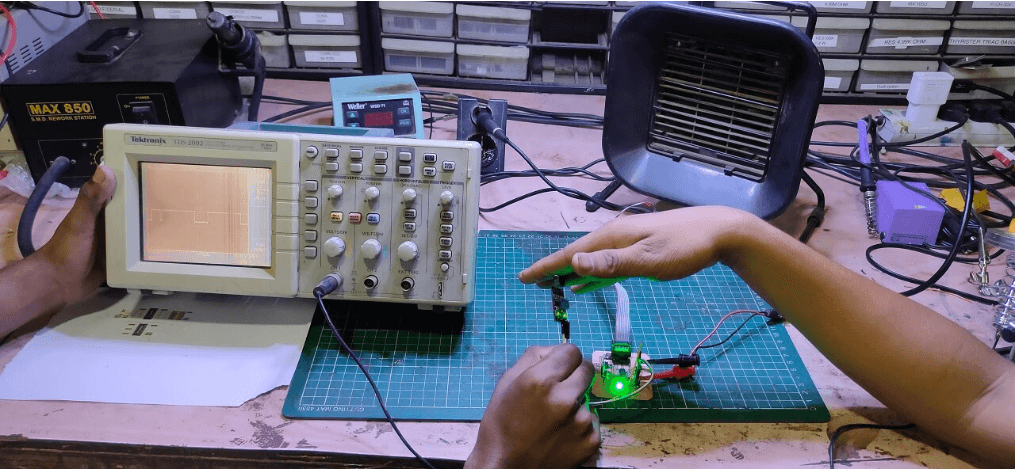
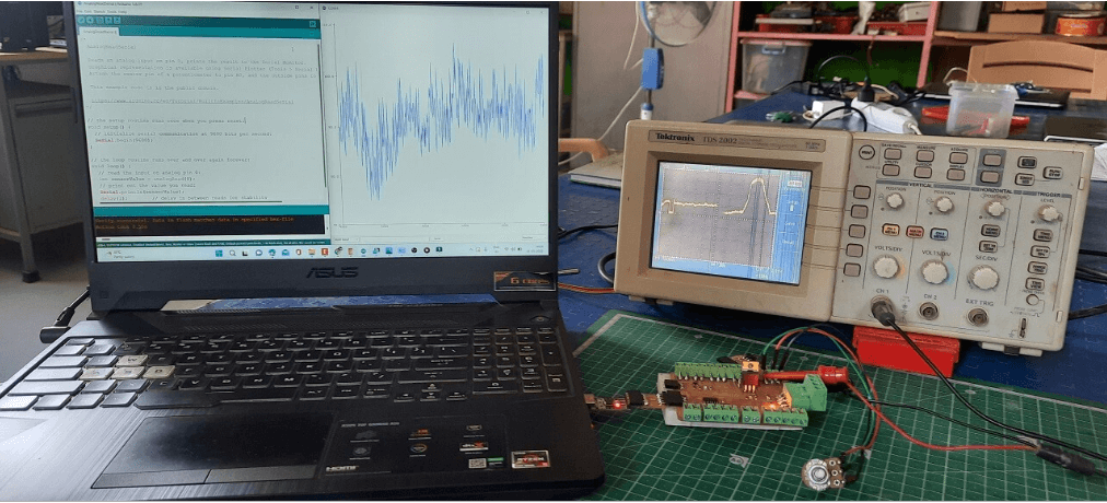
To probe the digital signal of an input device, we connected IR sensor to the Input devices
board and activated the sensor after programming the board through arduino IDE.
First connected the board to DSO (Digital storage oscilloscope) and probed in to sensor's
digital waves as shown below.
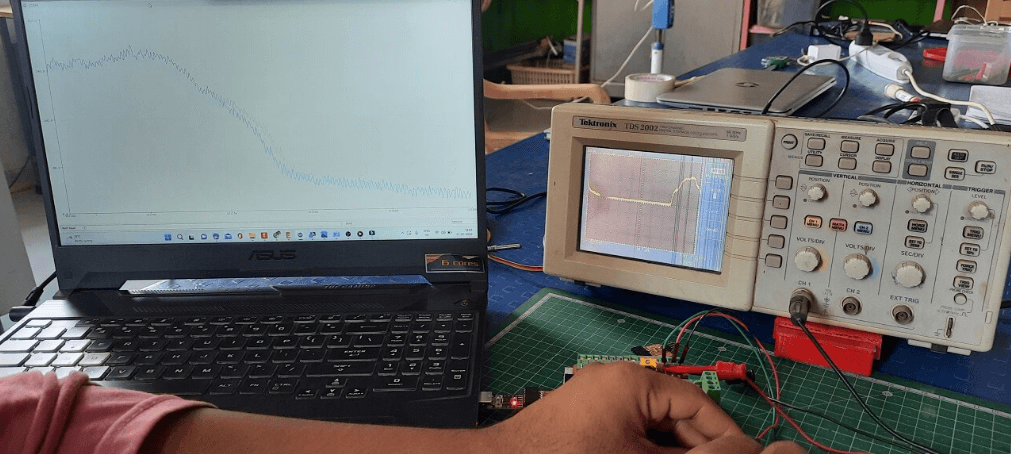
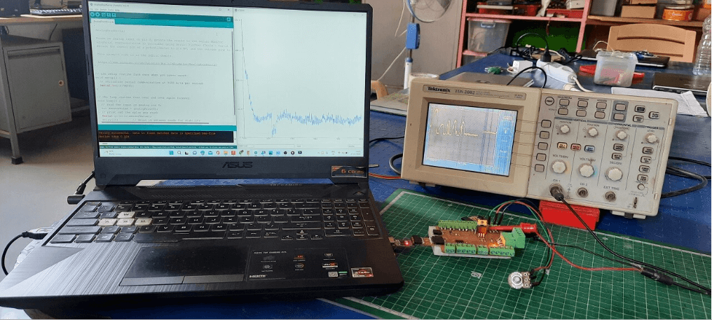
Later to probe the analog levels of an input device, we connected potentiometer to the Input
devices board and progammed the board for analog read through arduino IDE.
After that we connected the board to DSO (Digital storage oscilloscope) and probed in to
sensor's analog levels waves as shown below.
I first made the board of Attiny1614, then the IC of that board flew away and if that IC was
not in stock then I made Attiny3216.
And if I had to work on another IC, I worked further on Attiny3216.
And if I worked on the next Attiny44 and my Bluetooth didn't work, I didn't have the IC
cloud this time then I saw everything this time and chose the IC.
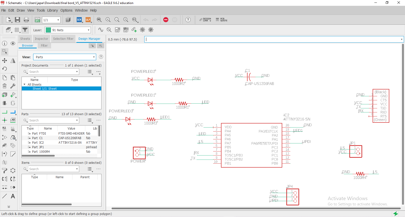
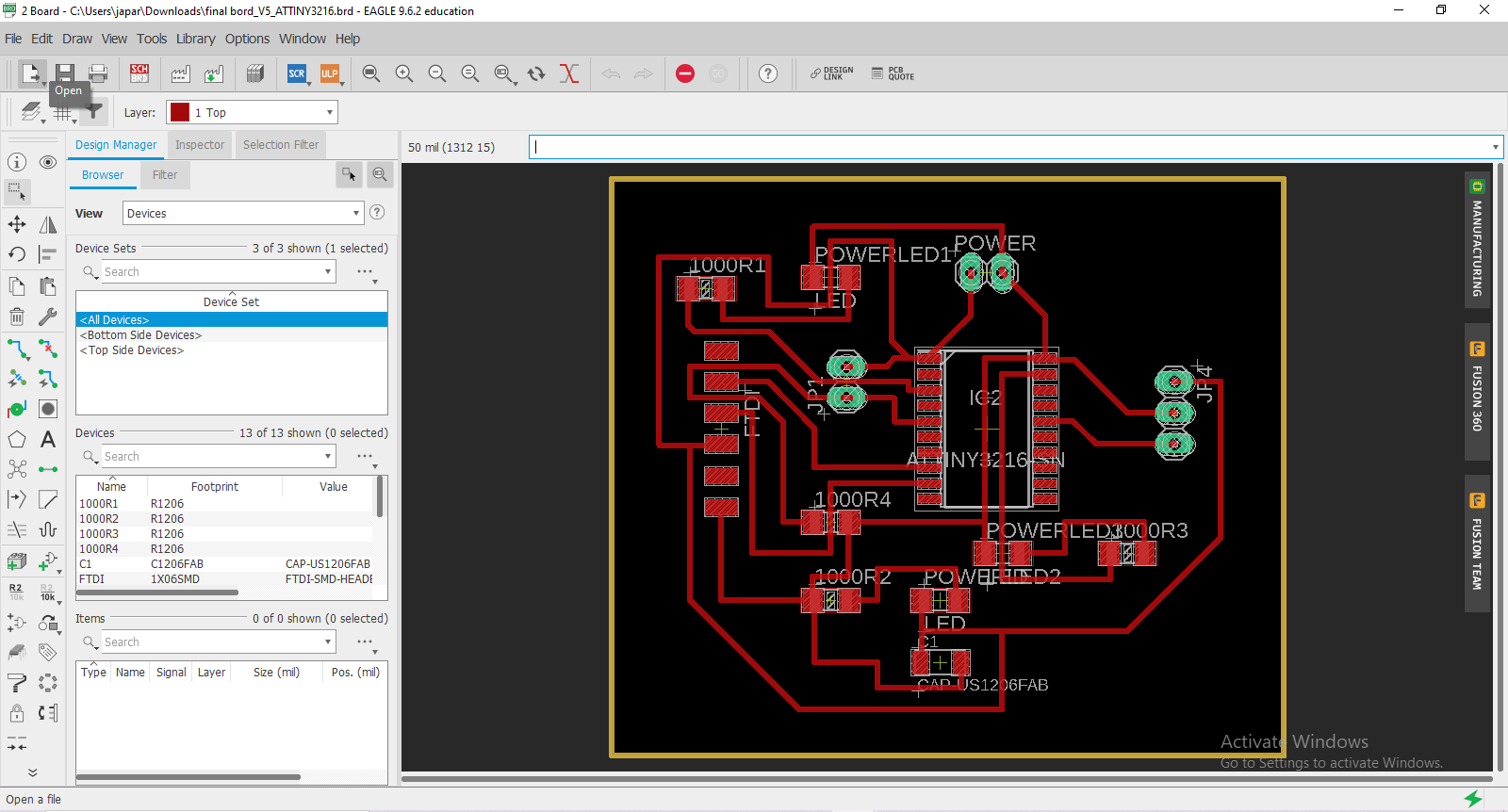
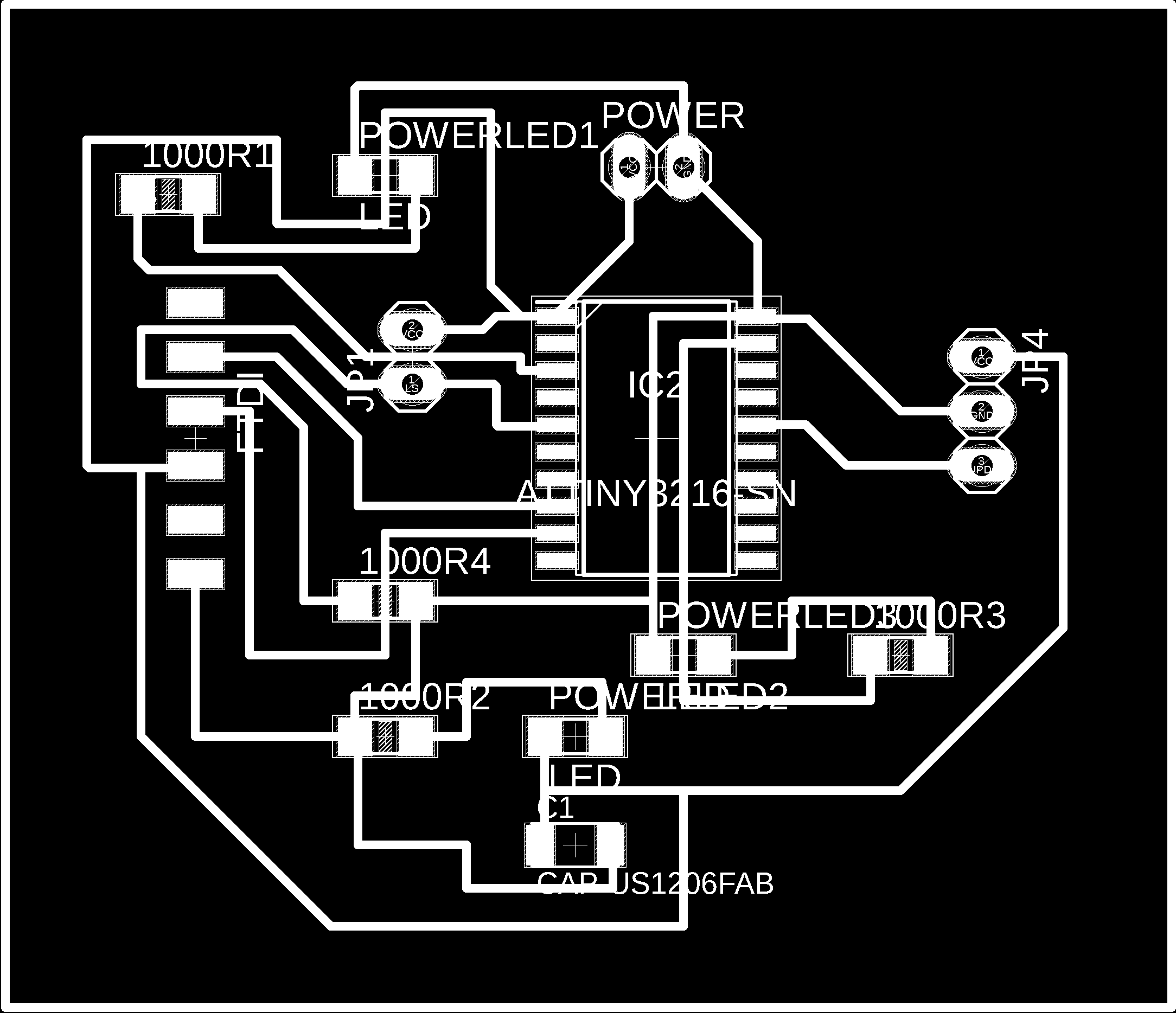
Individual Assignment
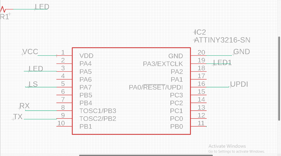
Make my final Project Board this week.
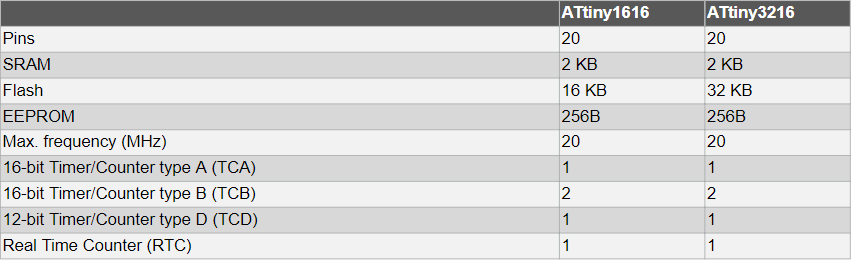
Microcontroller Use Attiny3216.
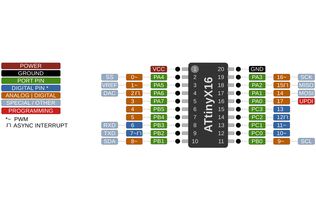
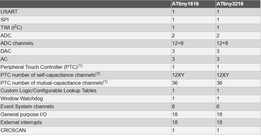
Attiny3216
What is the Attiny3216?
The ATtiny3216 line of microcontrollers contains an 8-bit AVR® processor with a hardware
multiplier that
runs at up to 20 MHz and comes in 20-pin packages with up to 32 KB Flash, 2 KB SRAM, and
256B of EEPROM.
The series makes advantage of the most up-to-date Core Independent Peripherals with
low-power capabilities.
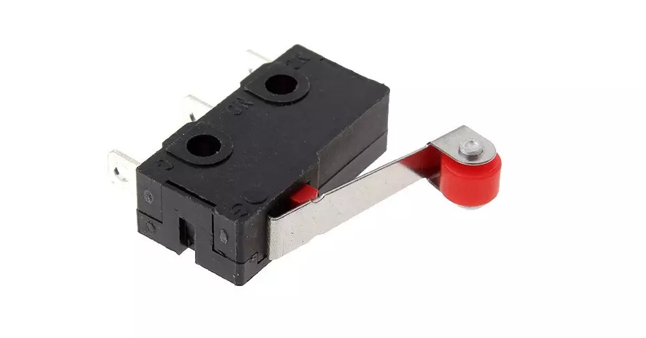
I have used the limit switch inside the input sensor.
What are Limit Switches?
Limit switches are used to automatically detect or sense the presence of an object or to
monitor and indicate whether the movement
limits of that object have been exceeded. The original use for limit switches, as implied by
their name, was to define the limit or
endpoint over which an object could travel before being stopped. It was at this point that
the switch was engaged to control the limit
of travel.
How does a limit switch work?
A standard limit switch used in industrial applications is an electromechanical device that
consists of a mechanical actuator linked
to a series of electrical contacts. When an object (sometimes called the target) comes in
physical contact with the actuator, the actuator plunger’s
movement results in the electrical contacts within the switch to either close (for a
normally open circuit) or open (for a normally closed circuit) their
electrical connection. Limit switches use the mechanical movement of the actuator plunger to
control or change the electrical switch's state. Similar devices,
such as inductive or capacitive proximity sensors, or photoelectric sensors, can accomplish
the same result without requiring contact with the object. Hence,
limit switches are contact sensors in contrast to these other types of proximity sensing
devices. Most limit switches are mechanical in their operation and
contain heavy-duty contacts capable of switching higher currents than those of alternative
proximity sensors.
The designs are generally simple and straightforward
They work well in almost any industrial setting
They exhibit high accuracy and repeatability
They are low power consumption devices
They can switch high-inductance loads
They can be used to switch multiple loads
They are simple to install
They are rugged and reliable
They typically have heavy-duty electrical contacts meaning they can be used to switch higher
levels of
current directly without the need to utilize secondary relay control
Limit switches also have several limitations, which means they may not be suited for every
application:
Because they rely on mechanical action, they generally are used in equipment that operates
at relatively low speeds
They are contact sensors, meaning they must make physical contact with the target for them
to operate
The nature of their mechanical design means that the devices are subject to mechanical wear
or fatigue
over time and will need eventual replacement
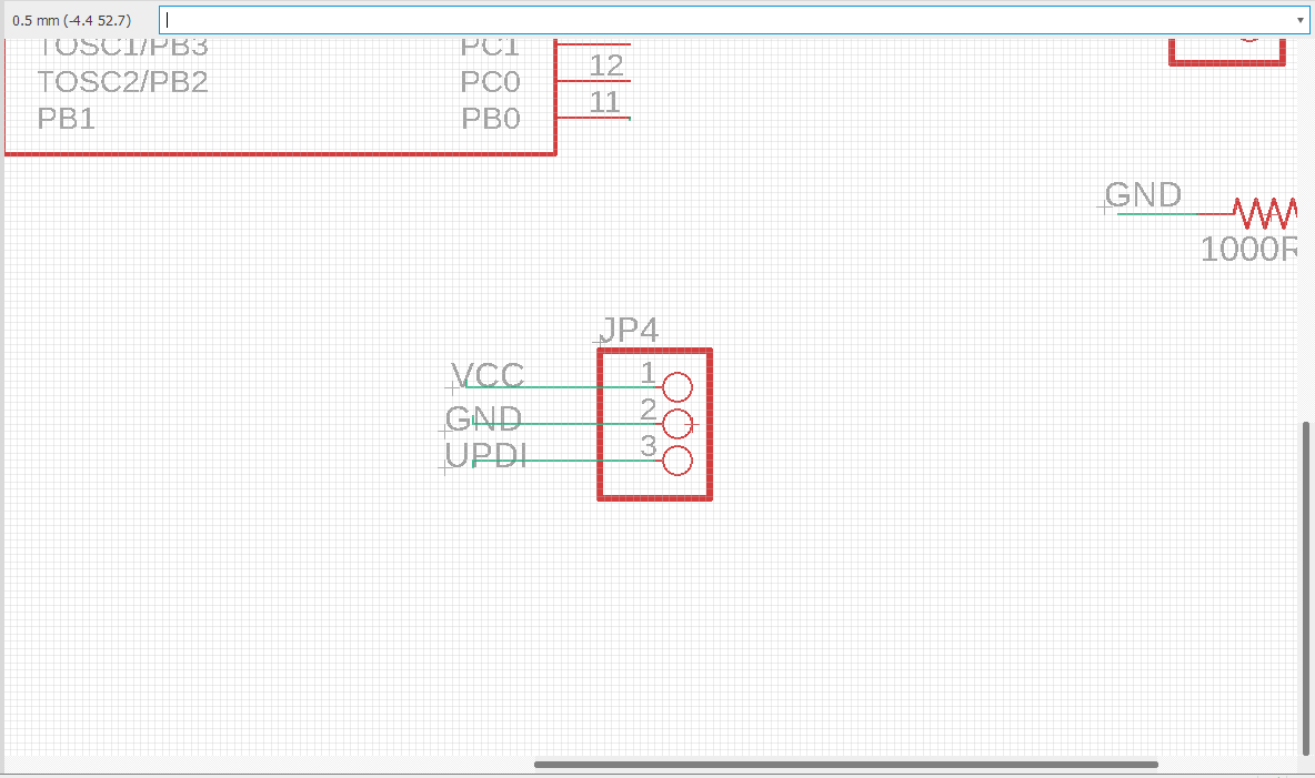
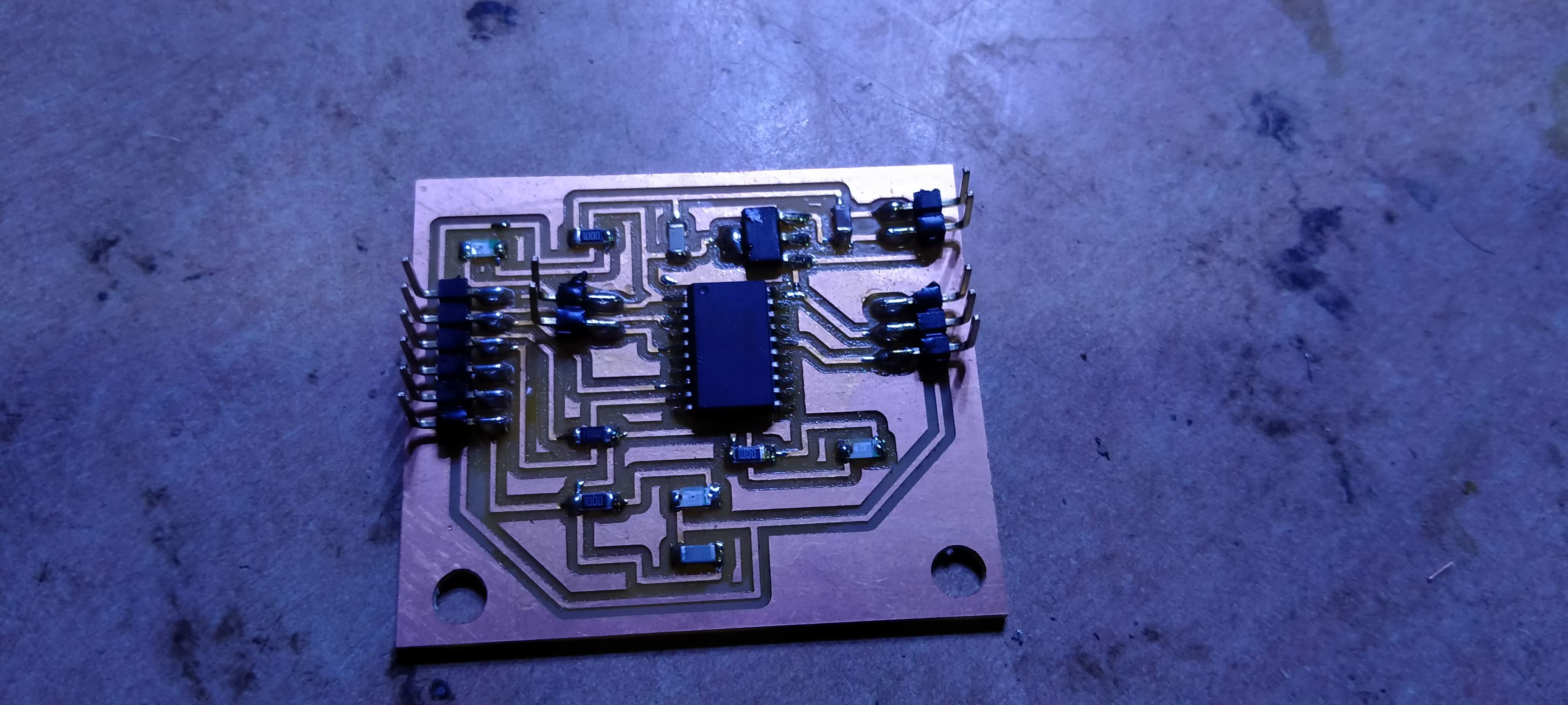
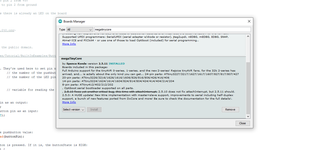
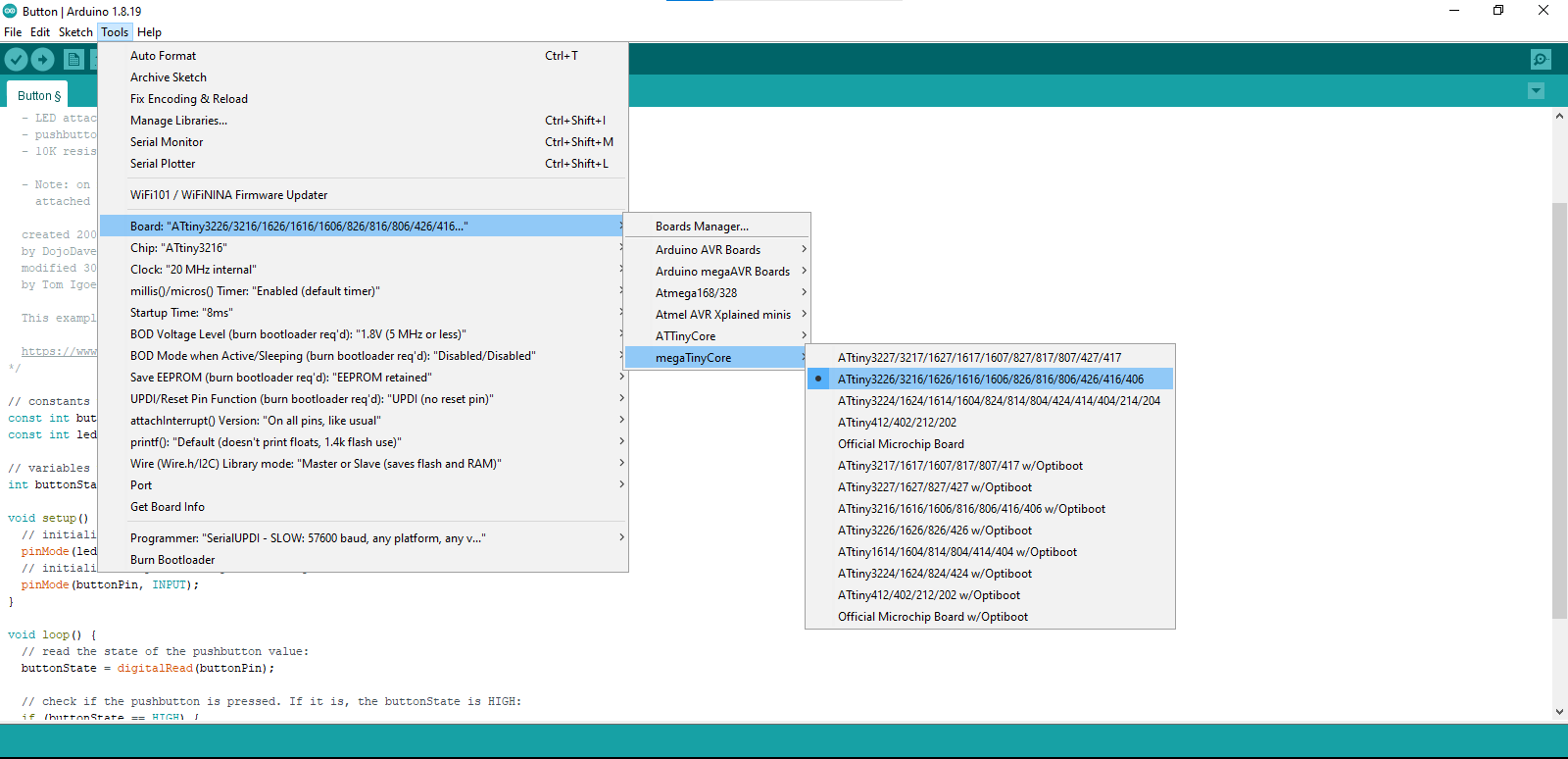
My Attiny3216 board programmed from the UPDI programmer.
Download Board "MegaTinyCore"
Then Select Board Attiny3216.
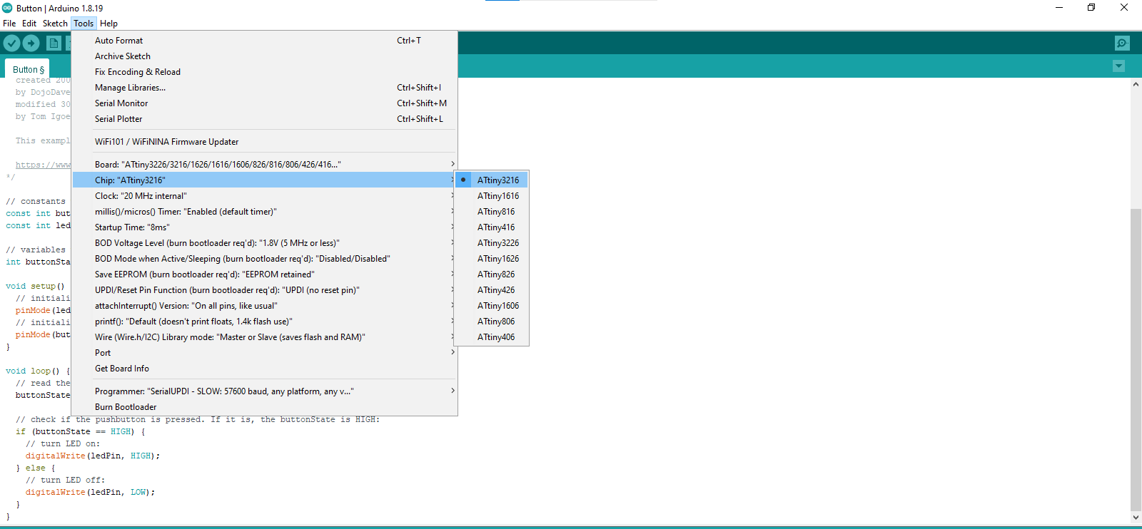
Select Chip Attiny3216
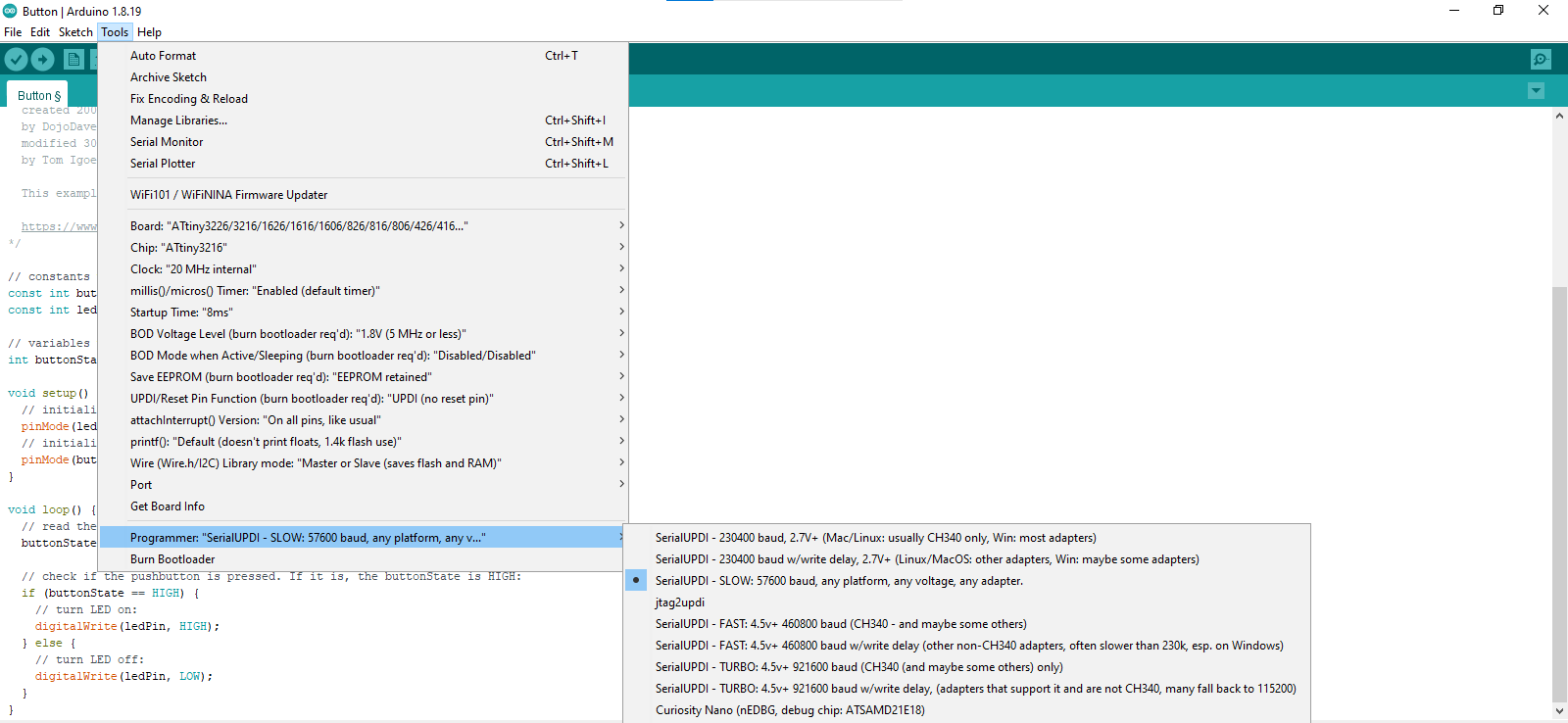
Select programmer.
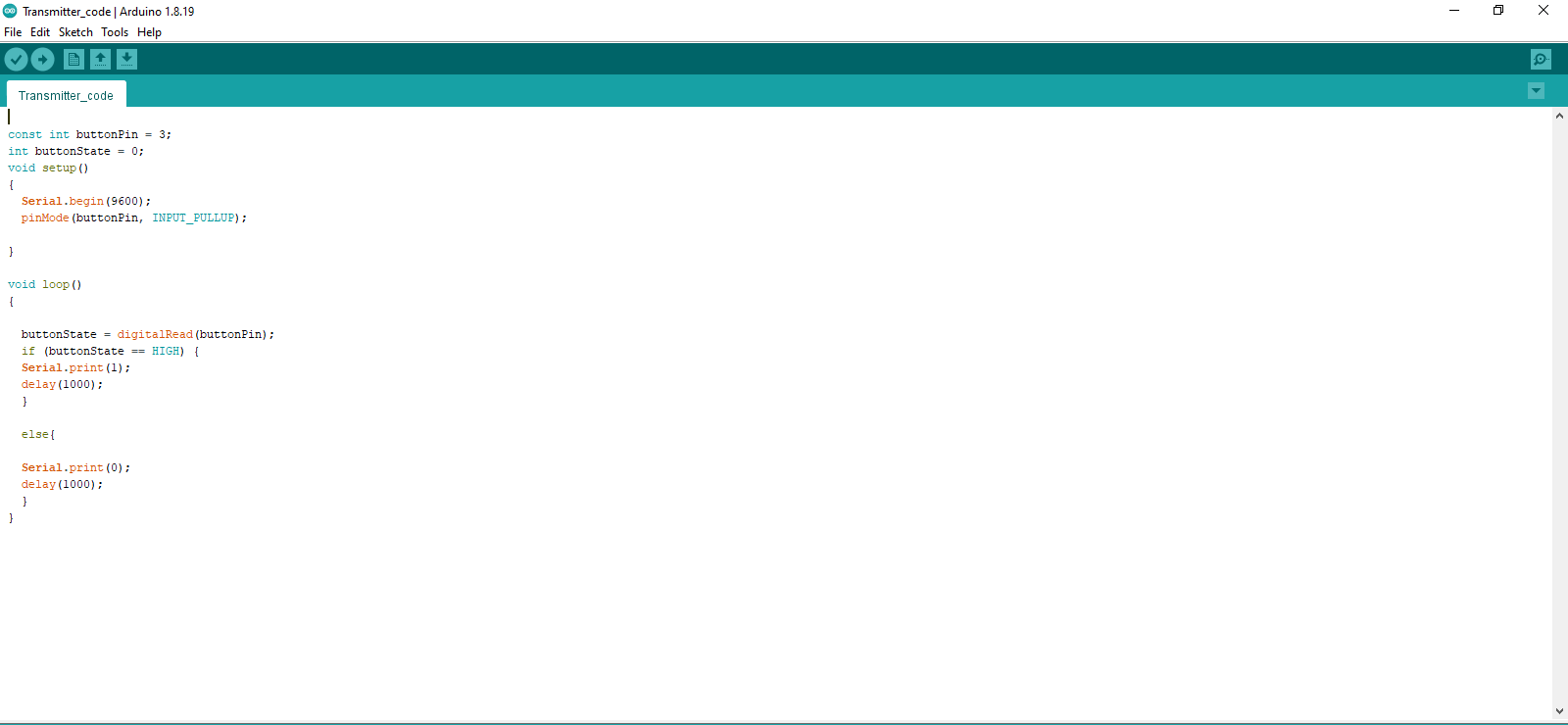
Upload Code
My button or my input device has pin number 3.
Final Output Video
The one that is my TX board sends a signal to the RX board.
It sends an ON signal to the LED when I press the button and an off-signal when the button
is not pressed.
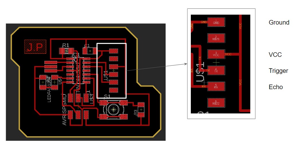
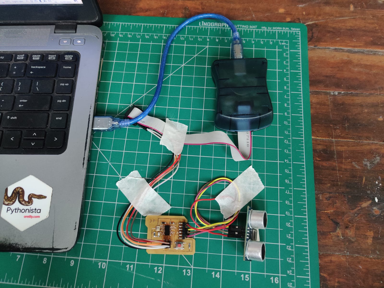
Ultrasonic Sensor ( Distance Sensor) using Attiny44 Board
I have done input based assignment which had push button based input which was not mounted on the board so a new assigment of taking variable input i have document here.
Input as Ultrasonic Sensor ( HC SR 04 ) for reading distance.
For making this project I have used my Hello World Board Week 7.
In this input project I have used the pinput shows below.
sensor has trigger and echo is singal which I have connected to pin 4 & pin 5 of ATTiny44.