Molding (see American and British English spelling variants) is a manufacturing
process that involves shaping liquid or malleable raw materials with a rigid
frame called a mold or matrix. This could have been created from a pattern or
model of the final product.
Molded furniture, molded home products, moulded casings, and structural
materials are all common uses for moulded plastics.
Casting:-
Casting is a manufacturing method in which a liquid substance is poured into
a mold with a hollow hole of the required shape and subsequently solidified.
To complete the process, the solidified portion, also known as a casting, is
ejected or broken out of the mold.
Epoxy, concrete, plaster, and clay are examples of casting materials that cure
after mixing two or more components together.
What is the difference between molding and casting?
Both processes are intertwined or, to put it another way, they are one and the same.
Both procedures entail pouring molten metal into a mould or die, which solidifies into the
shape of a cavity mould or die.
The manner by which molten metal is poured is the primary distinction between moulding and
casting. Metal
is poured under pressure in moulding, but it does not require any external pressure in
casting due to the
low viscosity of the metal, which allows it to move freely under gravitational force.
Moulding also offers you the finished result, but this is not always the case with casting,
and you may wind up with an unfinished part depending on your final product requirements.
(after-casting machining required)
Casting uses a one-time mold but molding can use molds on repetition too.
There are three basic machining operations in the milling process.
Surfacing.
Rough cut.
Finishing.
For each of these three procedures, I'll create a tool path as shown below.
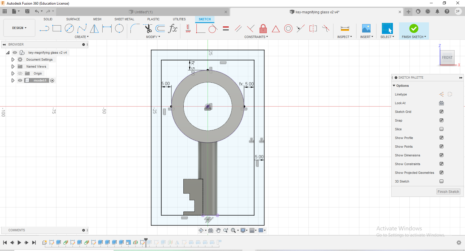
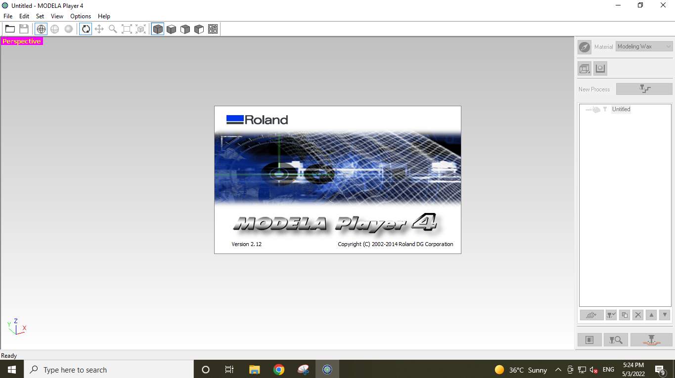
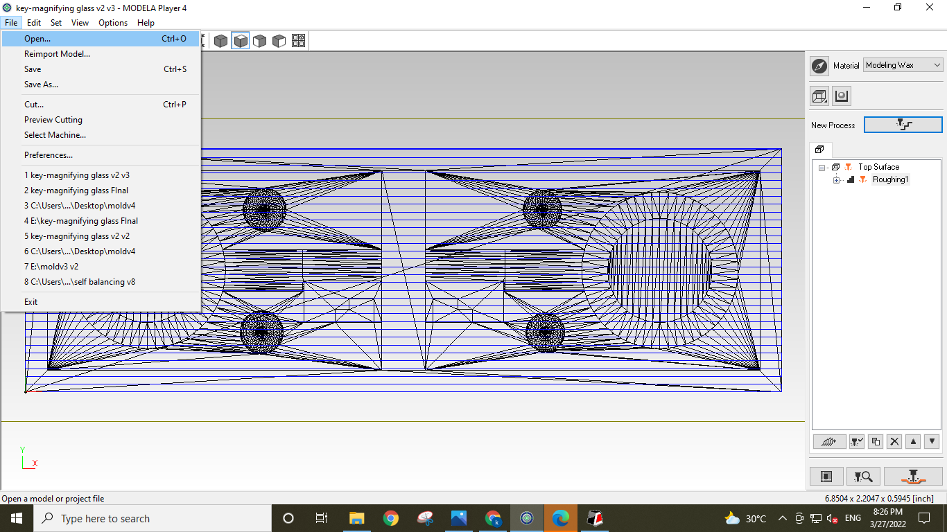
open the Modela Player 4.
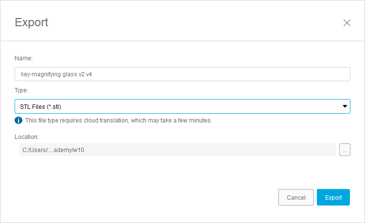
.Import the Mold Design. As I mention the file I am using is an STL format file.
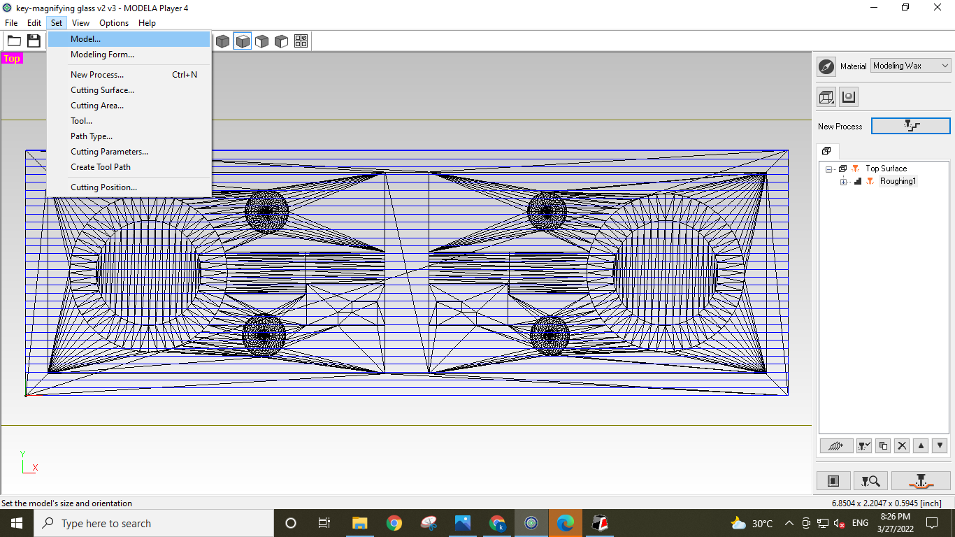
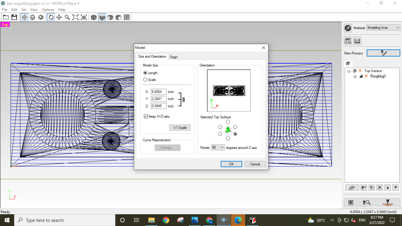
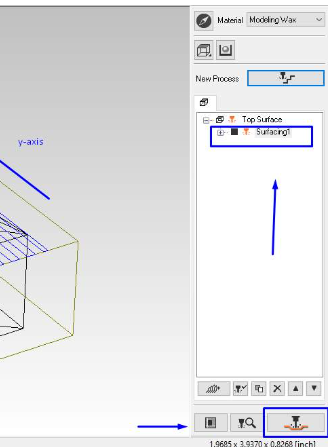
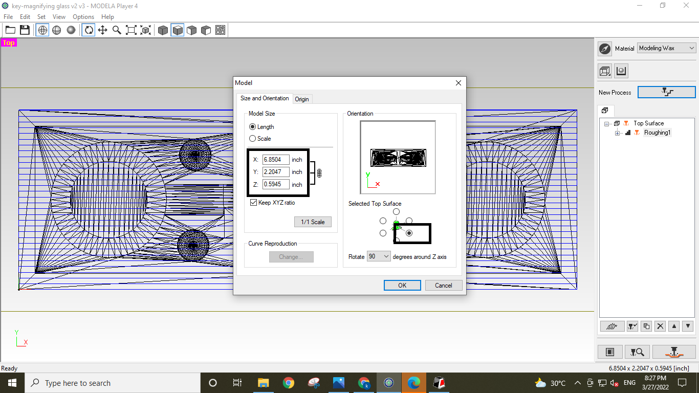
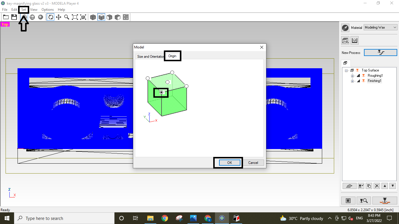
Then Setting the mold's size, orientation, and place of origin for machining.
Toolbar>Set>Model>
There, I choose the top perspective while choosing the top surface side. As seen in the
figure, I also put the matching origin at the corner of the machining wax block.
It's time to make the first cut for an operation that is currently surfacing. Because the
Wax block I'm
using doesn't have a consistent surface, surfacing is crucial. There is a slope there.
Therefore, if I neglect
this step, it's probable that the mould will be cut in an uneven manner from the topside due
to the unevenness
in the surface.
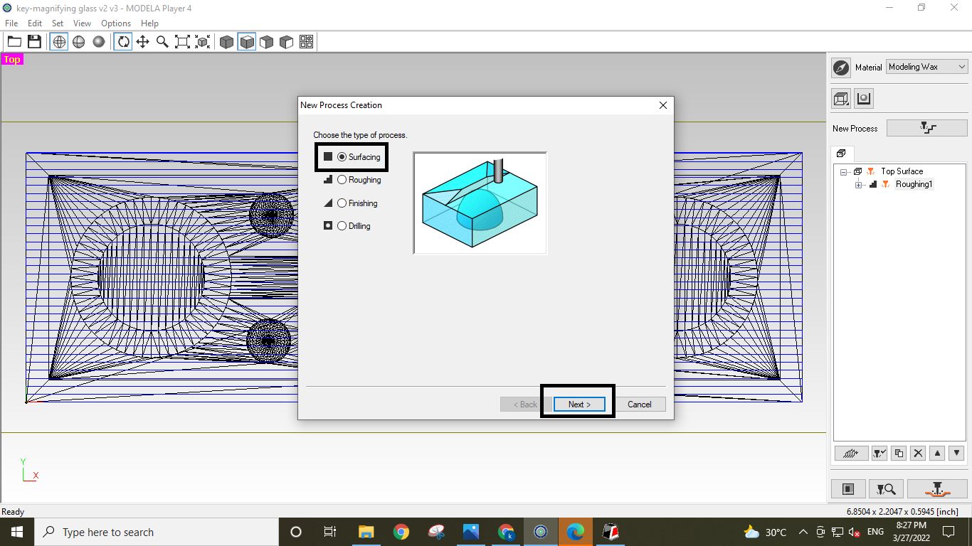
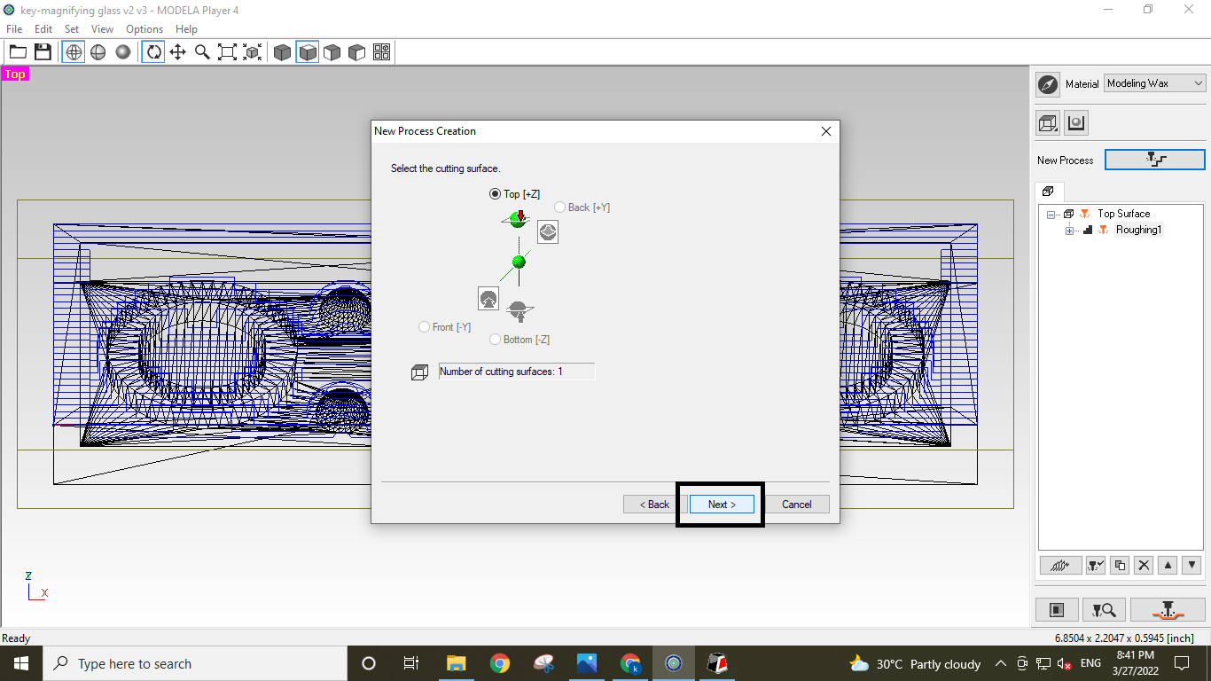
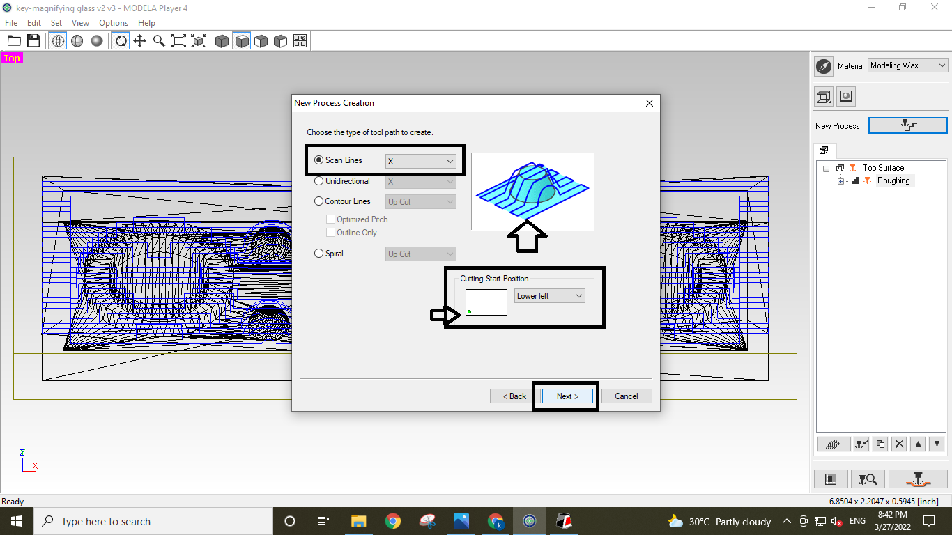
to design a toolpath for a surface. To establish a new Processing Path, I click Surfacing
after selecting the new process.
The next step is choosing an appropriate surface for surfacing. which, naturally, is Top
along the Z-axis.
The surfacing can also be carried out from the block's side in either the X or Y direction.
But in my situation,
I believe it is needless.
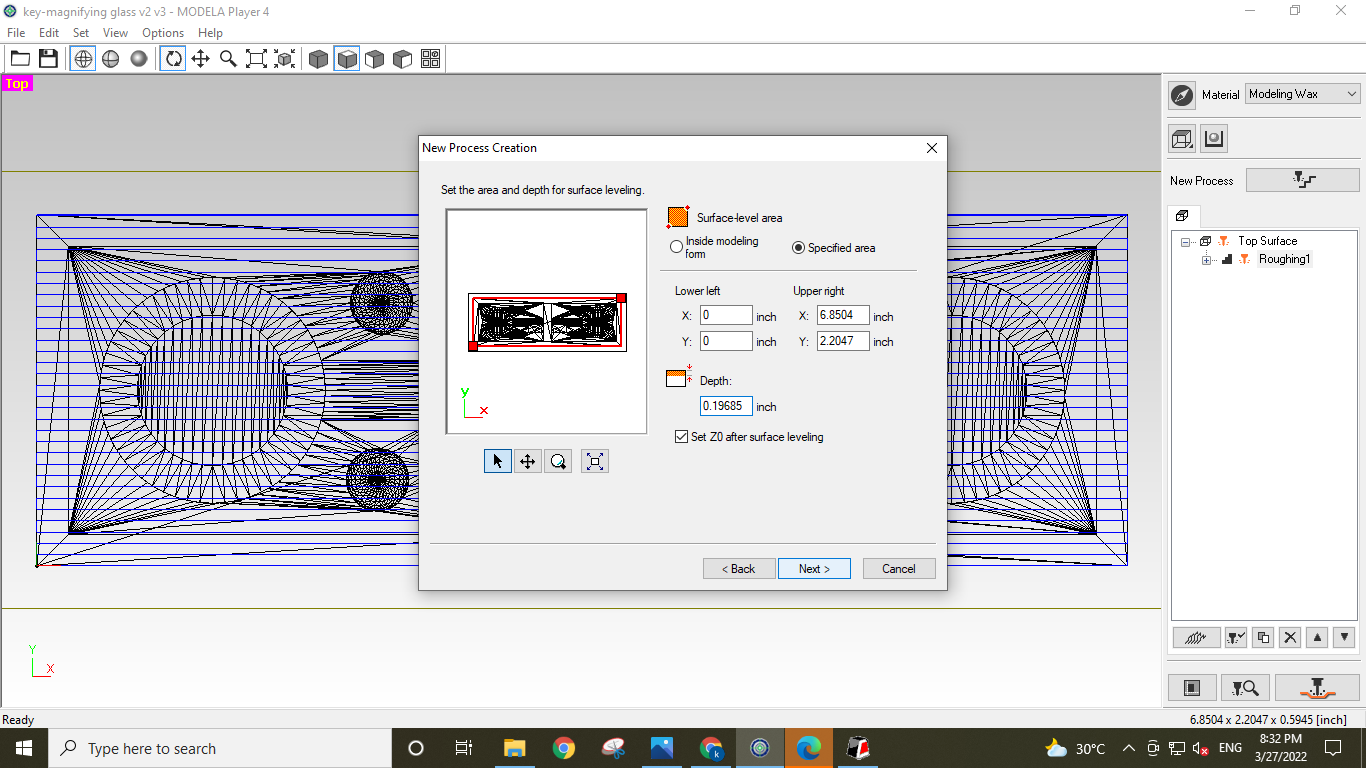
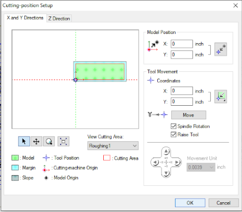
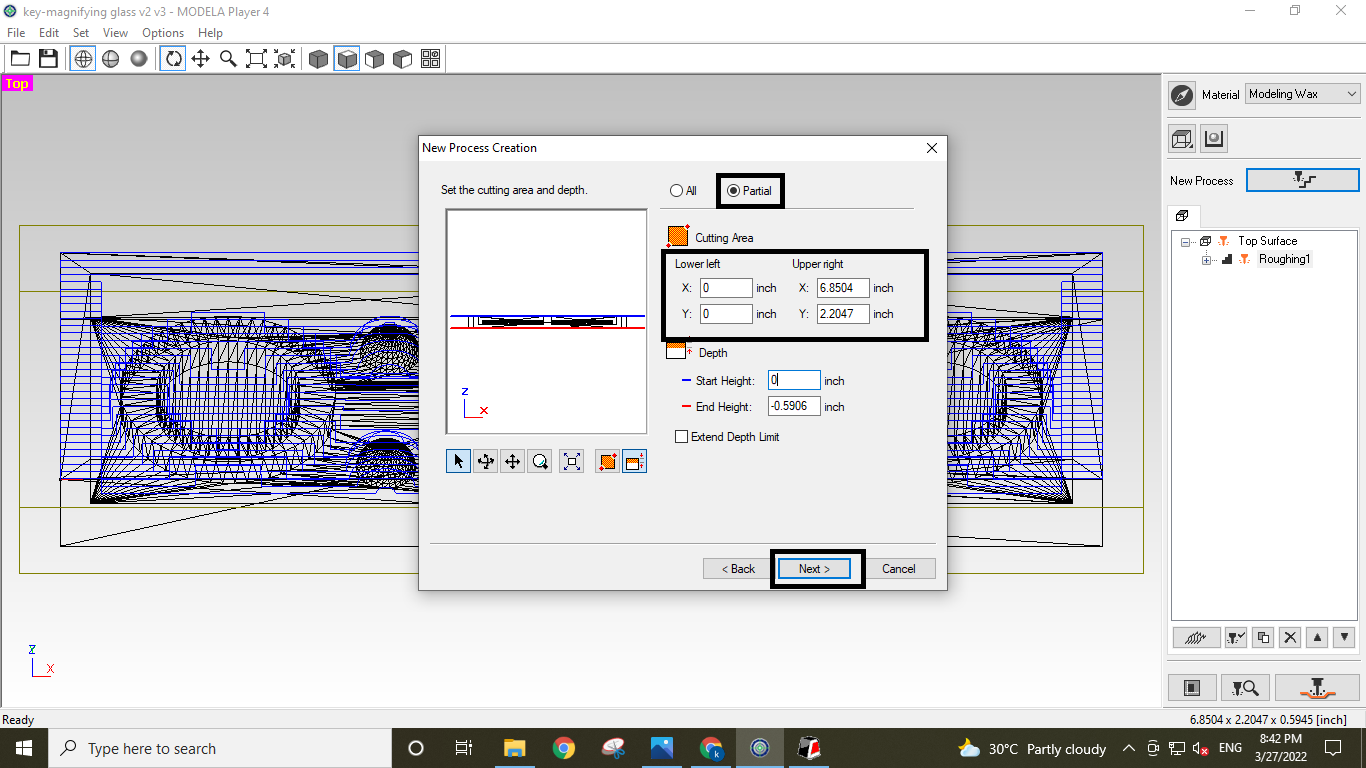
Setting the depth and area of surfacing comes next. I alter it as needed by choosing a
particular spot for my wax block.
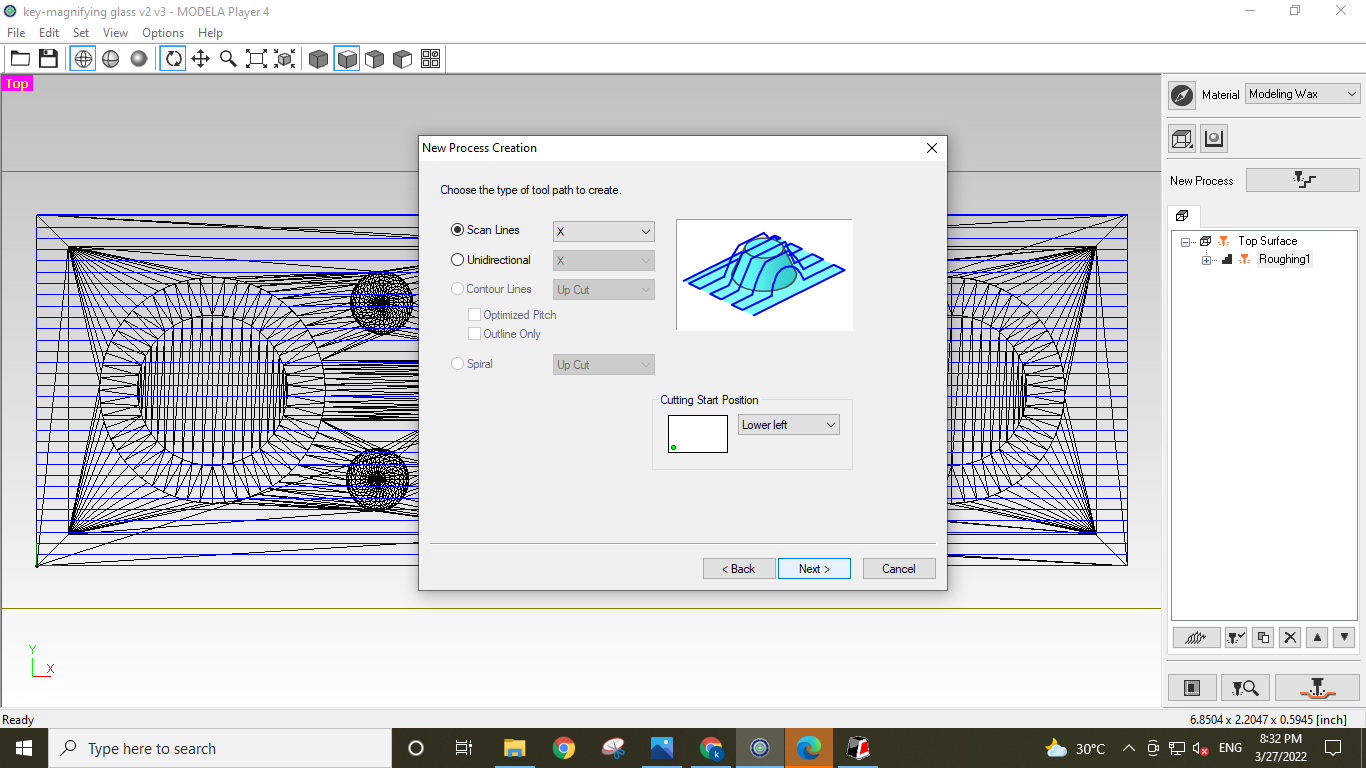
I must now select the tool's movement vectors in this phase. Because my main goal was to
create a surface plane and also in the
Y direction, I chose Y in the state of the X and X-Y options. The Y direction will be faster
because it has travelled a longer 100mm.
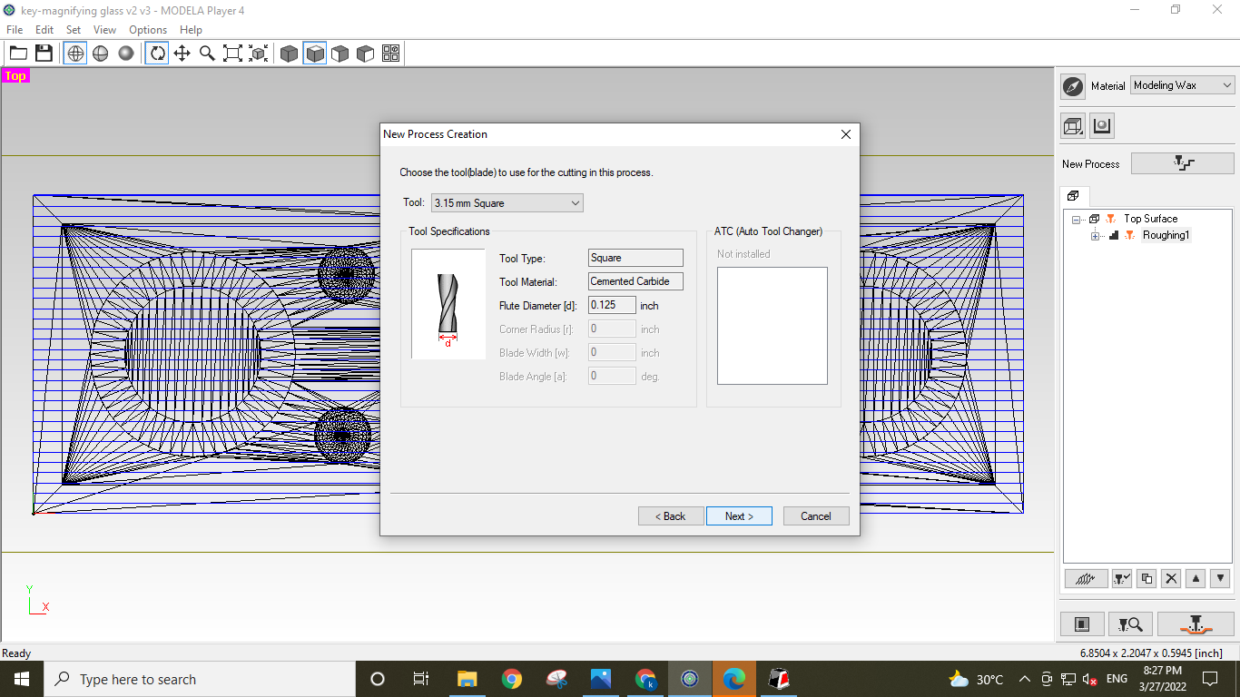
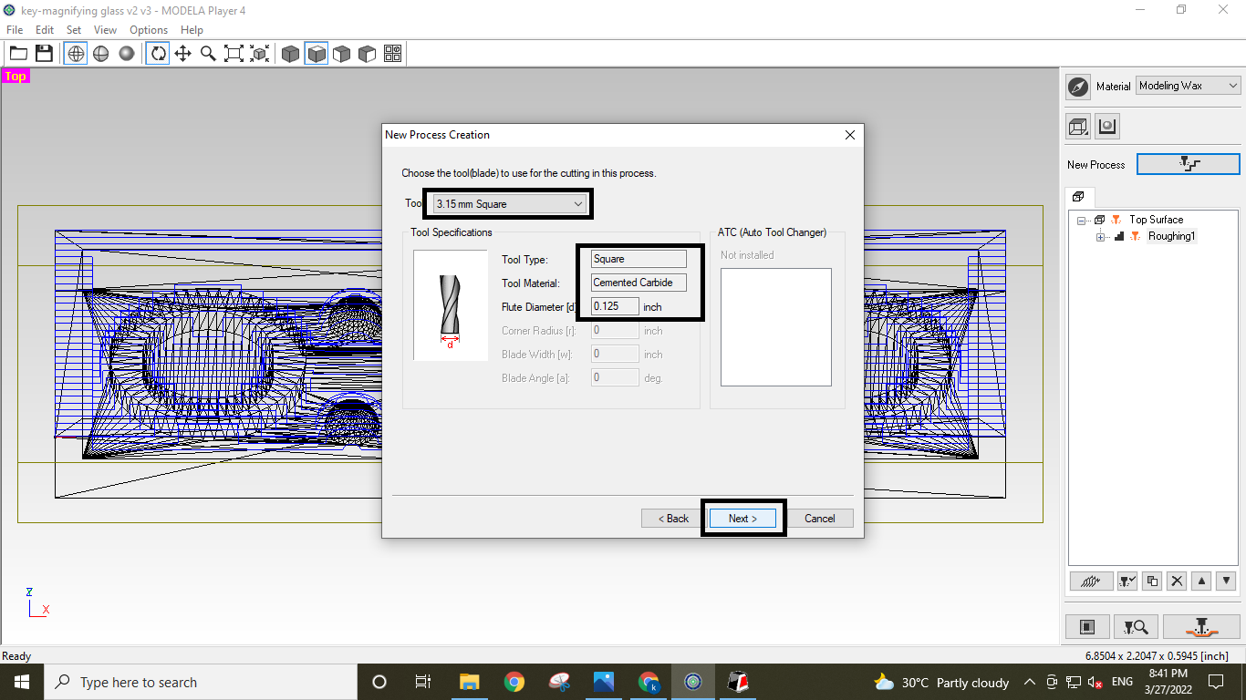
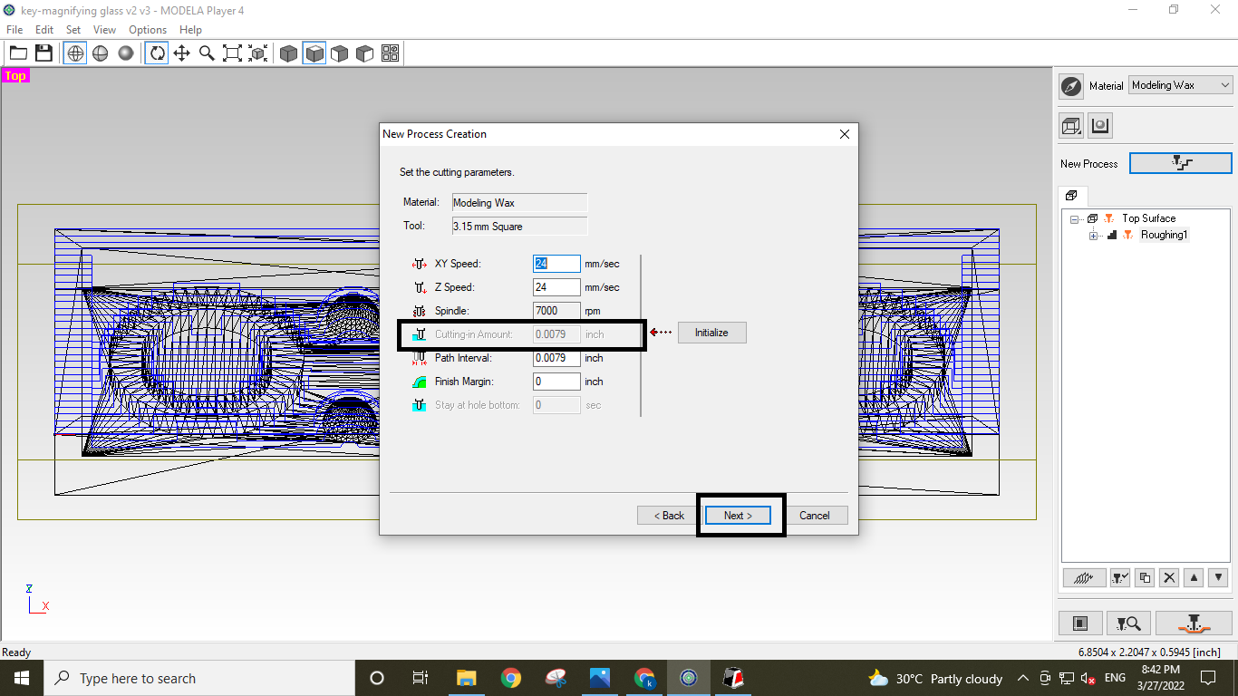
Select Cutting Tool.
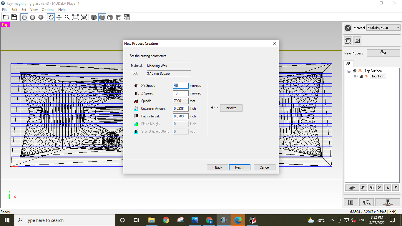
I have to choose the cutting parameter in this phase. The cutting quantity each tool pass
can be altered in this phase, but I leave it alone.
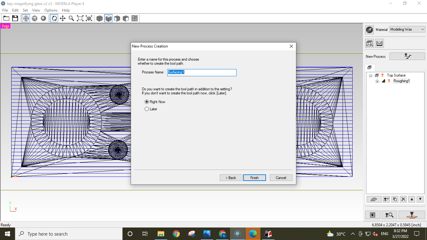
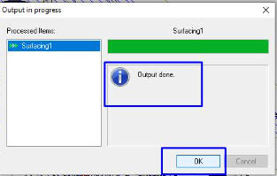
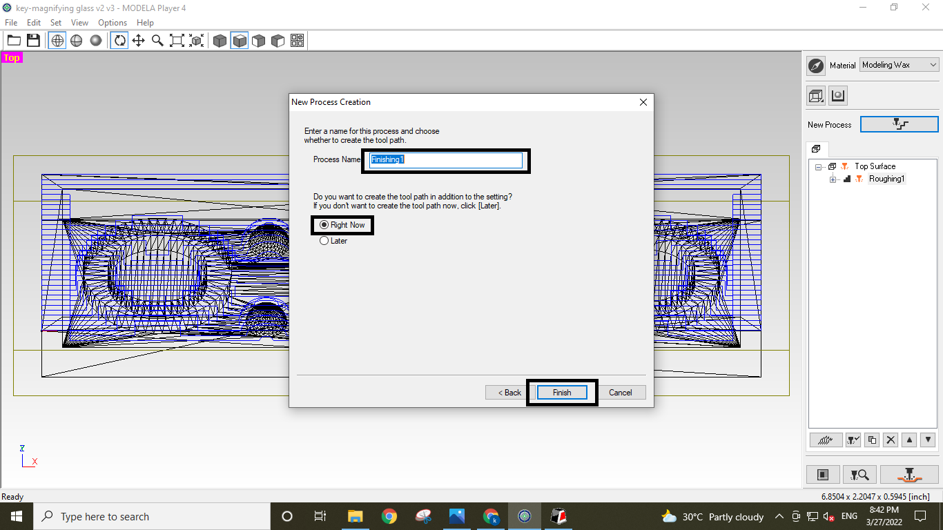
It's time to give the tool path a name now that it is virtually complete. It was clearly a
given. I
click it now to complete the process since I want to generate it on time.
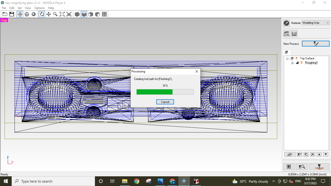
Tool path ready
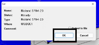
The tool path definition is displayed in an open window. I suppose that I don't take it
seriously and press the "ok" button.
press ok to start the surfacing.
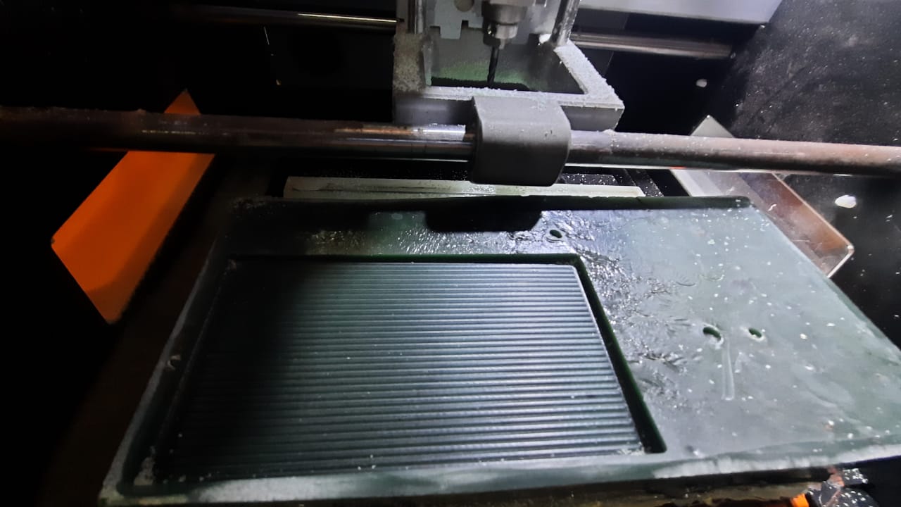
On the wax block I'm using, this is how the finished surfacing looks.
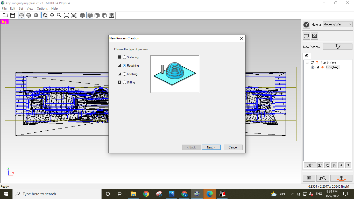
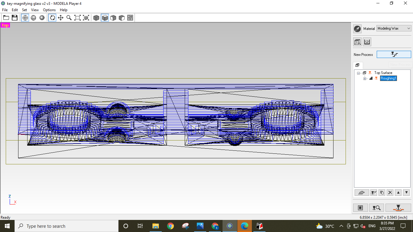
Roughting
In a similar vein, I make a second cut to create a mould for it.
a rough cut, which. Prior to the finish cut, the rough cut is applied to
remove the maximum amount of material from the machining process. Its primary
goal is to produce a quick machining operation while keeping the object's shape,
which need not be exact.
to assemble a basic toolpath. To establish a new Processing Path,
I click on the new process and then rough. I use the same flat endmill
bit for rough-cutting as well as the same process and parameters.
Rough cut
Finishing
Open File.
CLick Set and Open model
Select Your Design Top view.
Then Check Your Design X,Y and Z Dimension.
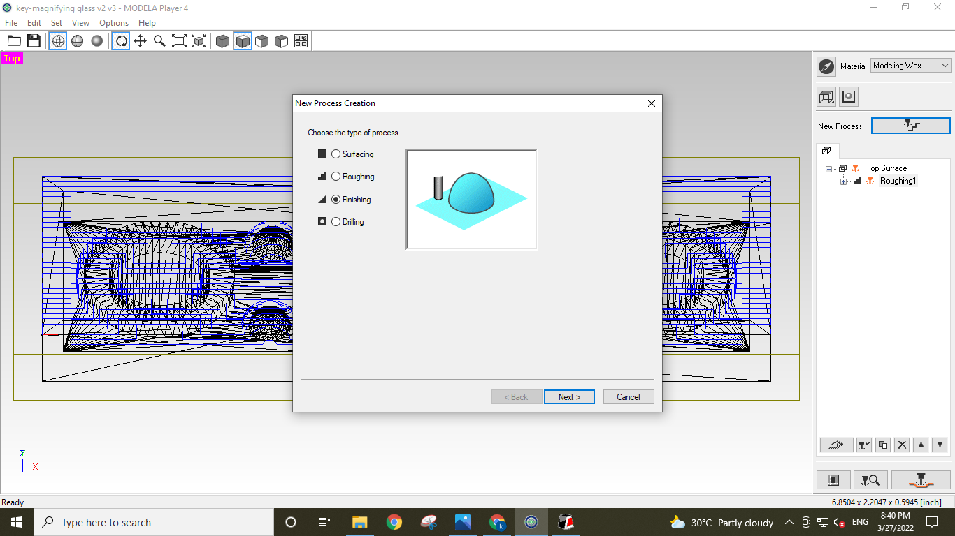
I followed the steps below to do generate the finishing toolpath. All the steps are same as
that I
followed for surfacing and roughing. Only difference is the process I have selected as
'Finishing'
for generating the toolpath.
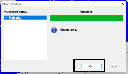
Let the 'Process name' be 'finishing1' and select 'Right now' option.
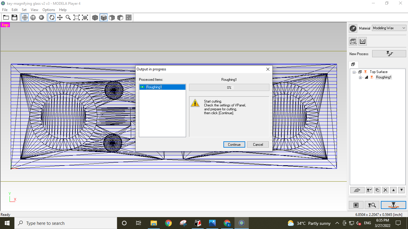
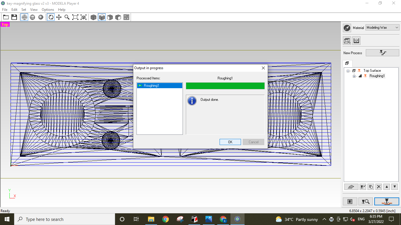
Milling a Mold:
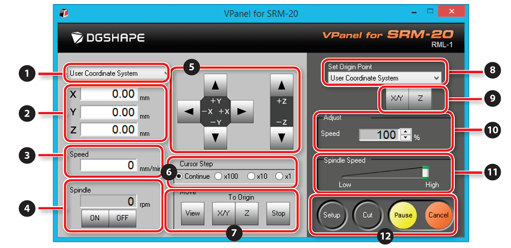
I utilised modela player 4 software to produce toolpaths for operations like surface,
roughing, and finishing paths in order to make a positive mould out of machinable wax.
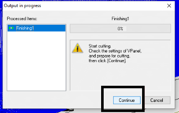
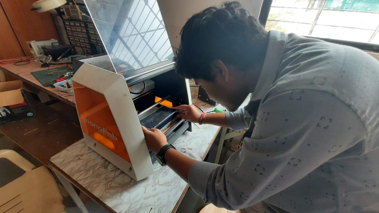
We need to utilise 'VPanel' for SRM-20 and set up the task, as well as the XY and origin for
the tool, before we can use modela and toolpath created.
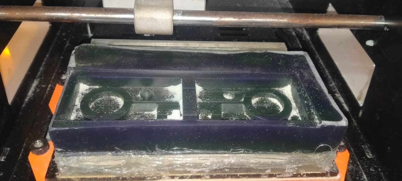
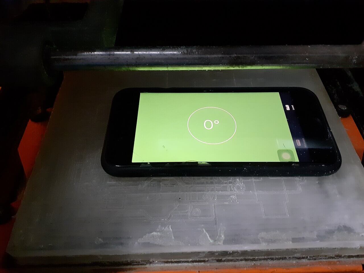
I put double-sided tape to the bottom of the stock, checked the level of the machine bed,
and added hot glue around the wax stock to ensure that the job is solid and does not move
throughout the machining process, as we do not use any other clamps during the machining
process.
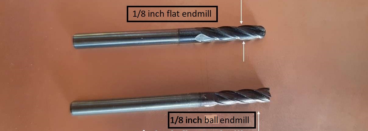
Selection of milling bit:
I use SRM-20 for the wax machining and a 1/8" flat end and ball endmill for the mould.
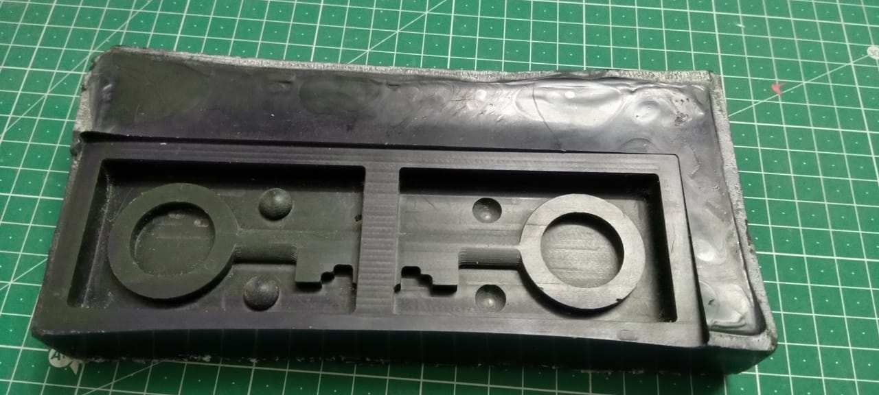
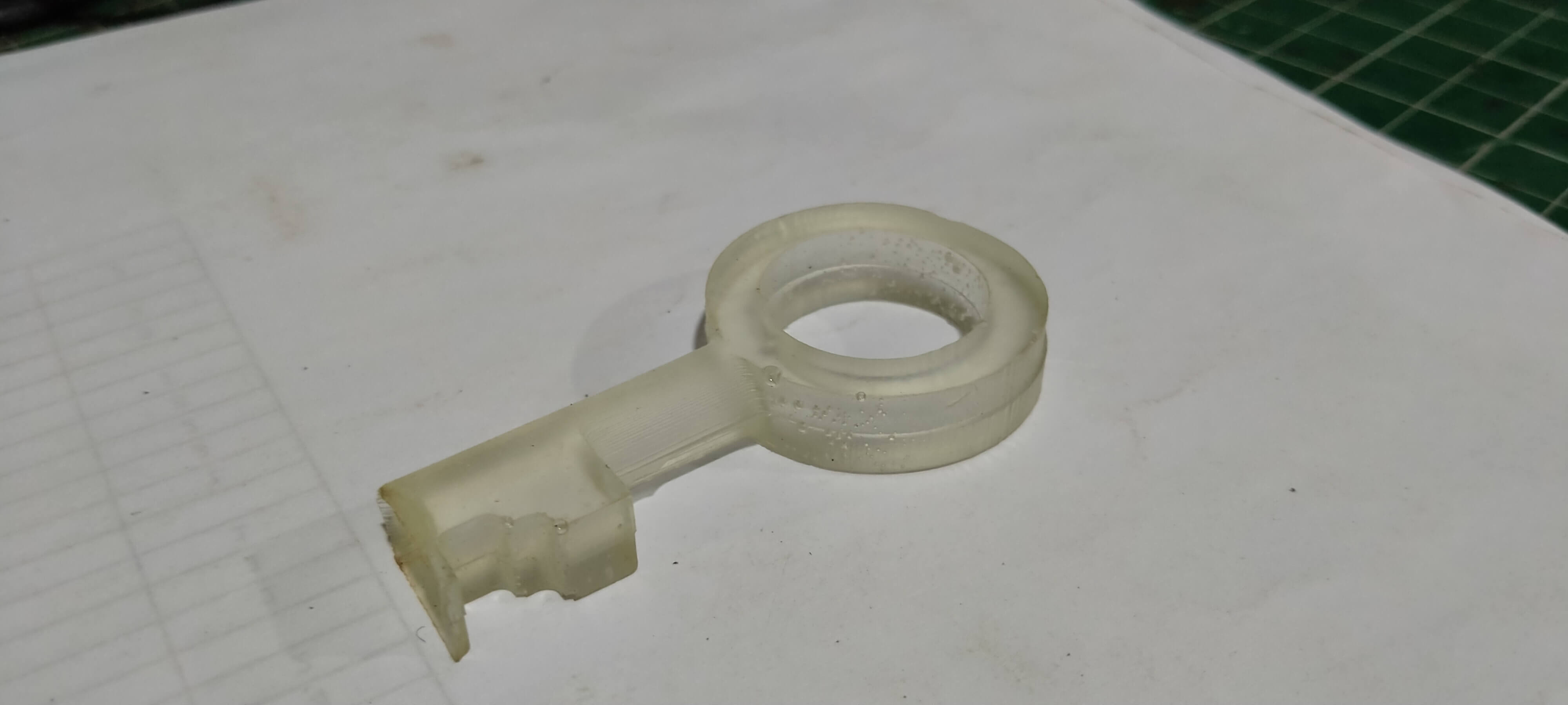
Final Output Photo
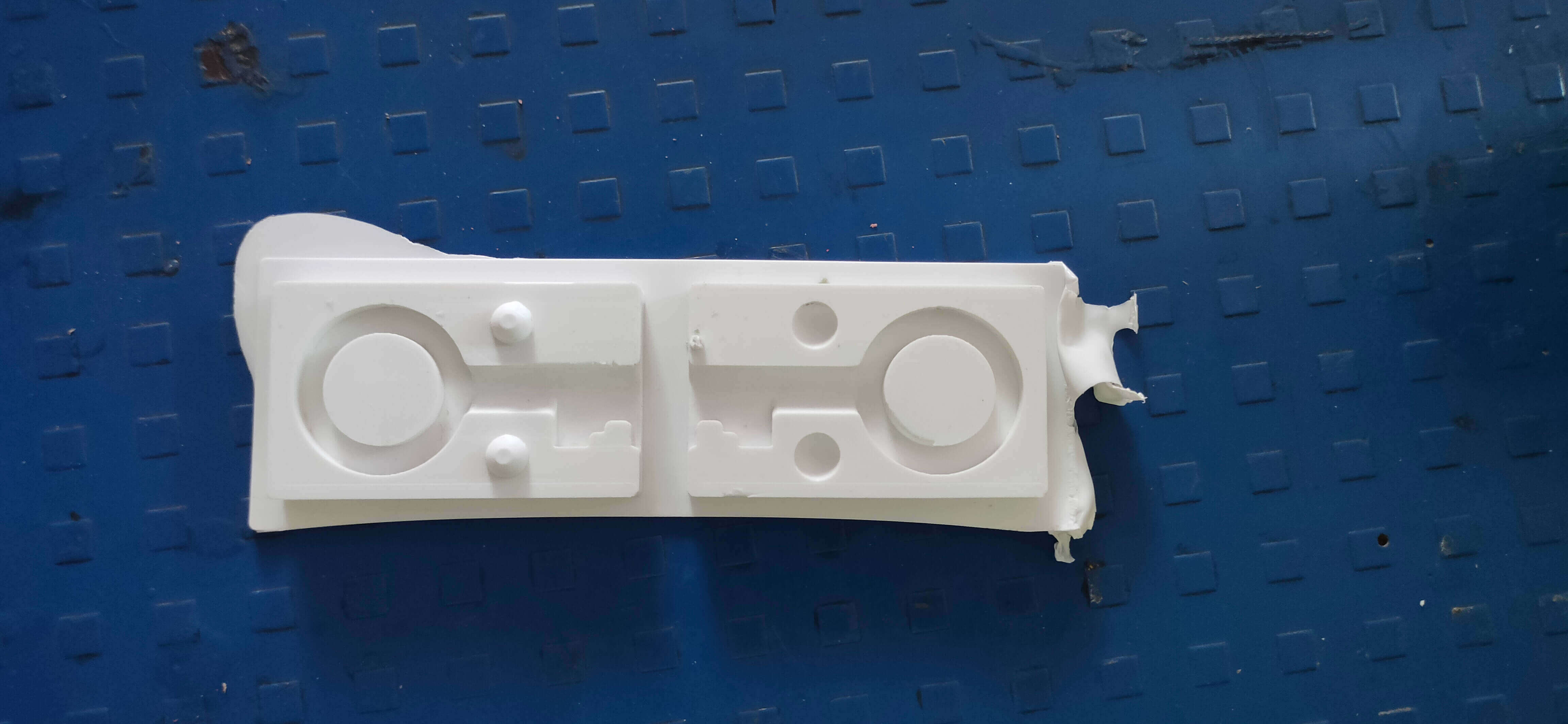
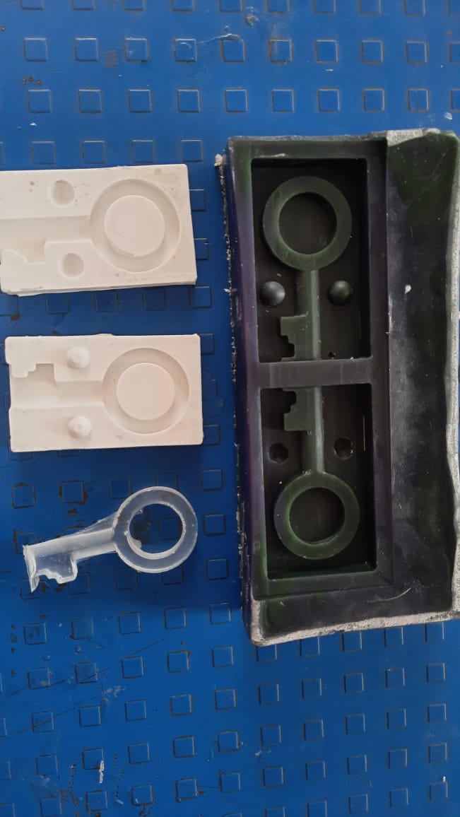
Negative Mold:
What Is the Nagative Mold
In order to replicate the model (thing) the mould was formed from, casting materials are
shaped using moulds,
which are negative forms. The finished cast will closely resemble the design of the hollow
mould form.
What is the positive mold
Convexity characterises a positive mould. Thermoforming employs both kinds. For the positive
mould, the heated
sheet is positioned over the convex form, and either positive or negative pressure is
applied to push the plastic
against the mold's surface.
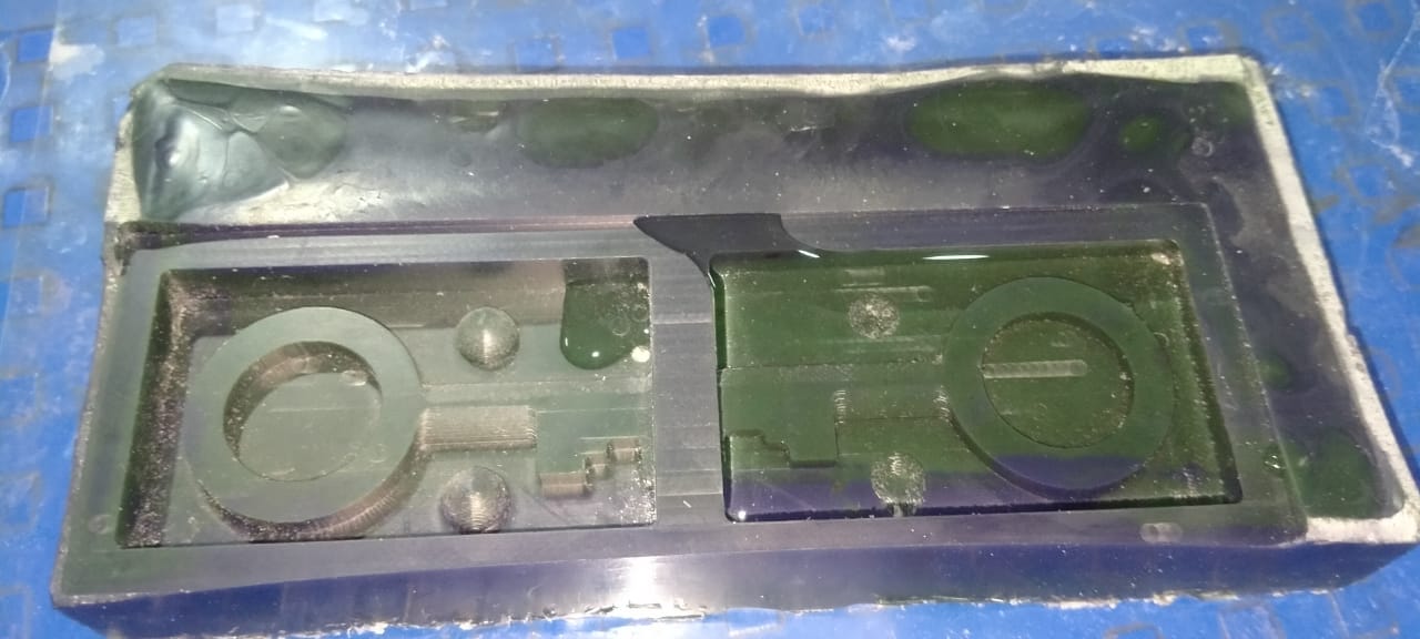
Volume Measurement:
The mould we use to cast the thing is a positive mould. The primary material we utilise
to create it at Fab Academy is silicon. for creating a successful mould. I need to figure
out how much silicon I'll need to make the mould. In Fusion 360, I have no idea how to
calculate it.
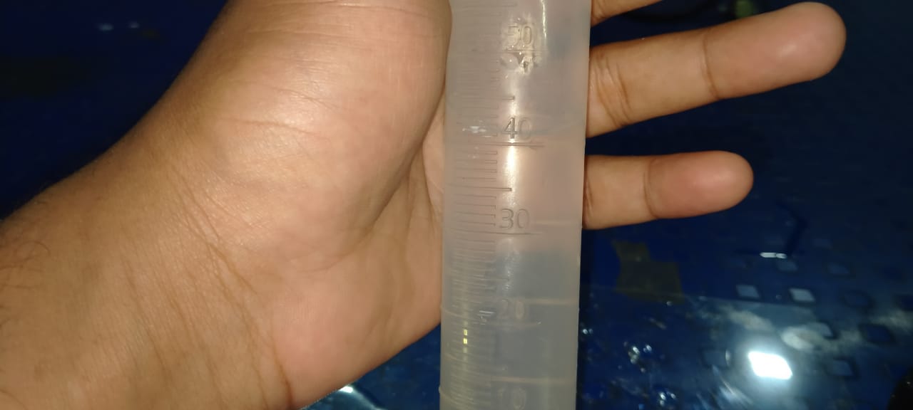
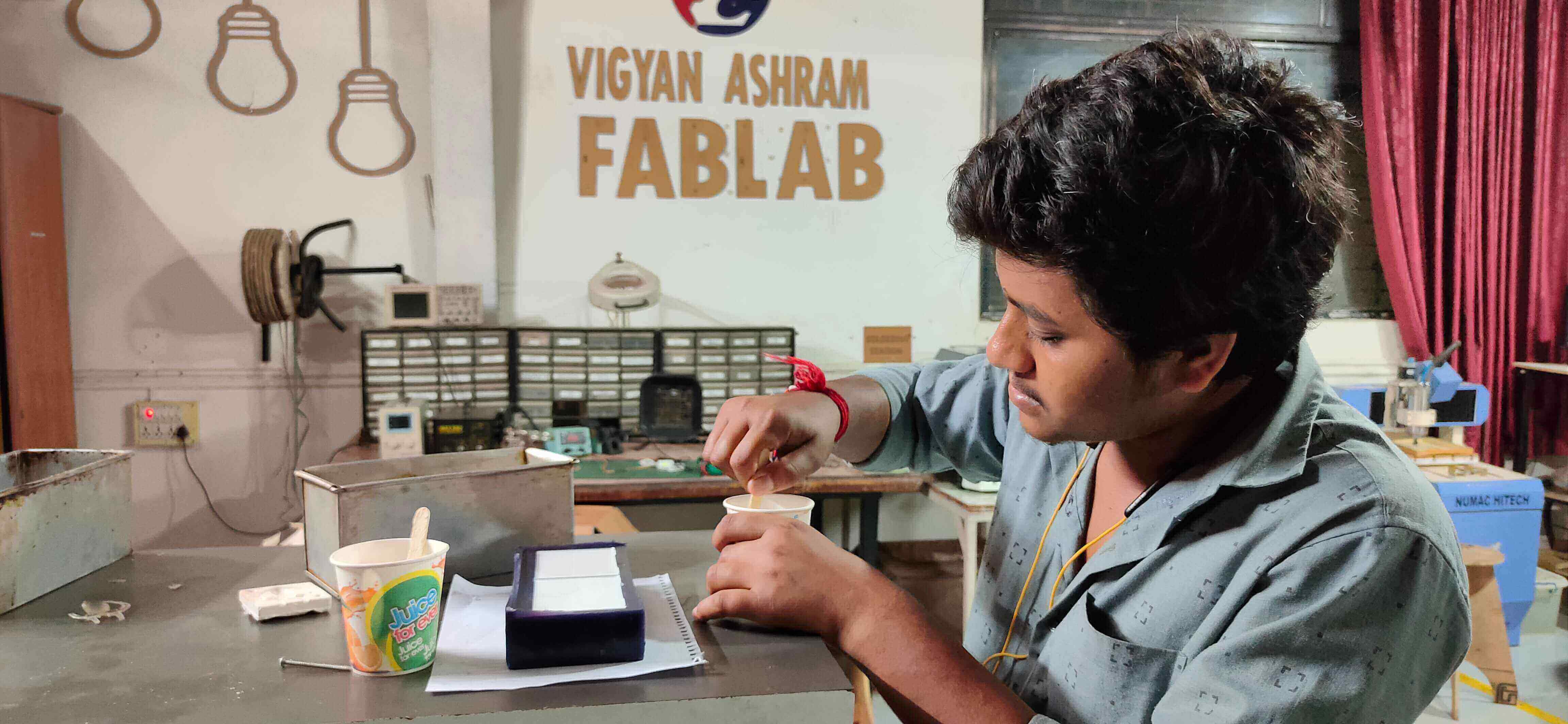
Instead of trying, I take the easiest road to measure. I measure the amount of water needed
to fill
each negative mould once I have poured the water into the mould. which I estimated to be
40ml. I will
need 40+40=80ml of silicon solution to make these moulds.
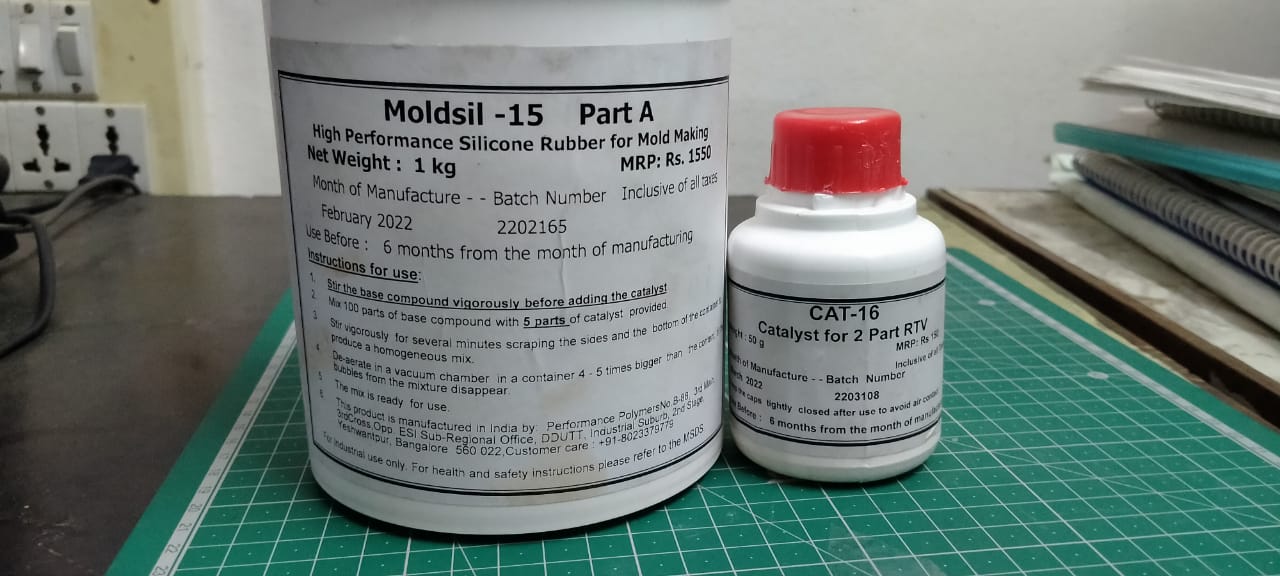
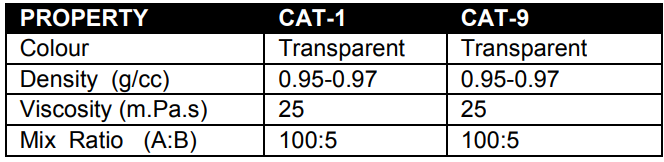
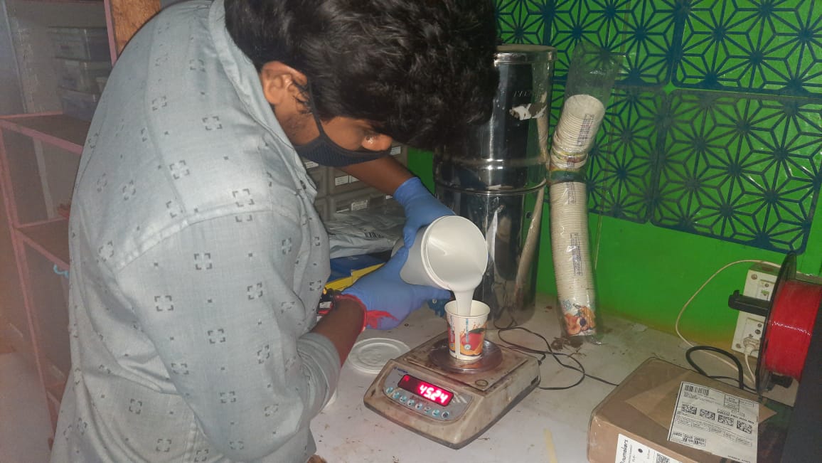
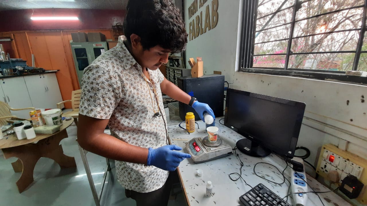
I create a slicon solution using this ratio in order to create a Negative mould. I weigh
them using a scale in our lab and mix it according to the stated ratio. The bubbles there
should be avoided.
Mix Ratio: Part A:80ML and Part B:4ML Use.
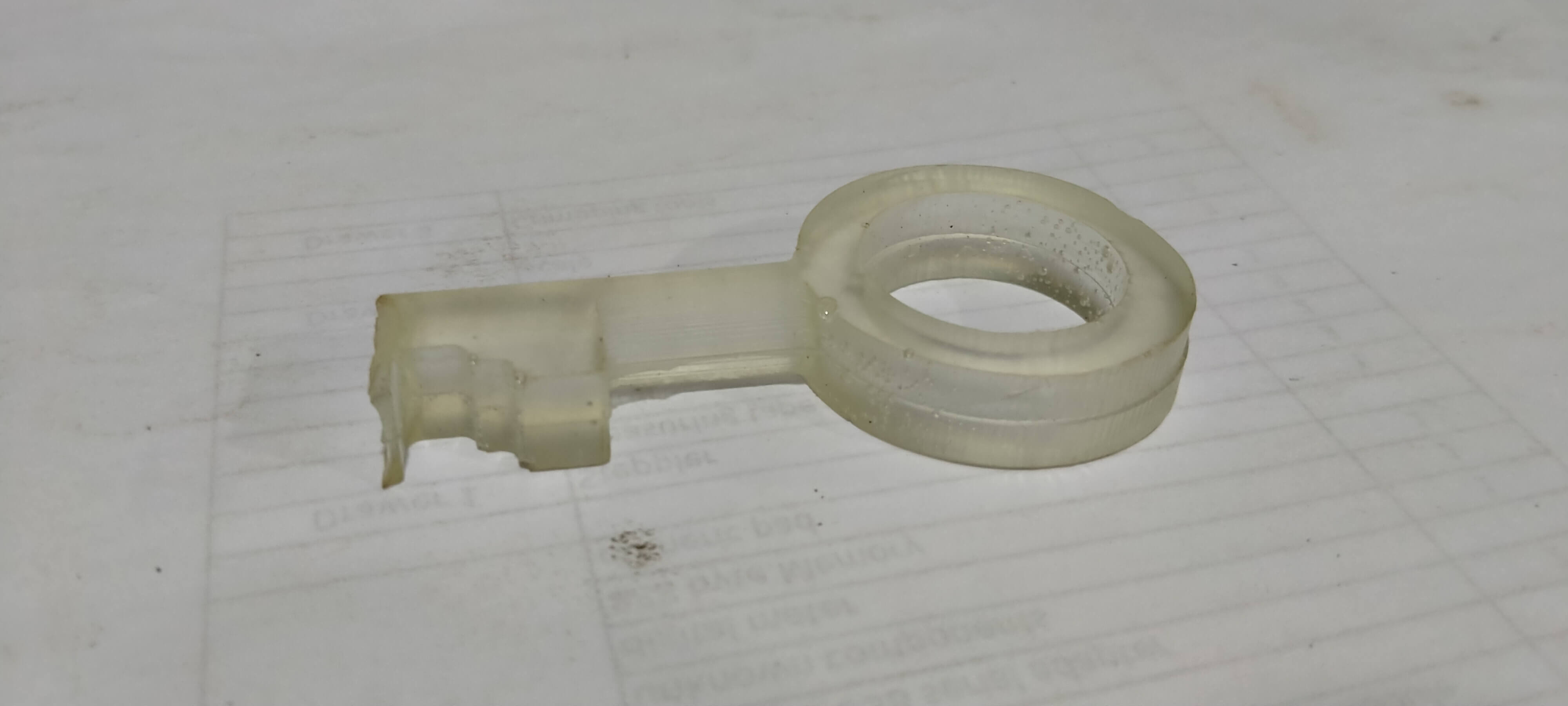
Positive mold:
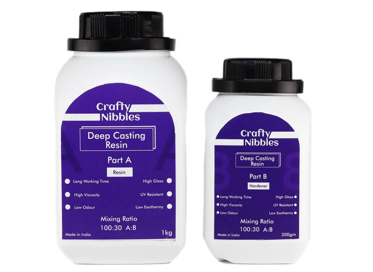
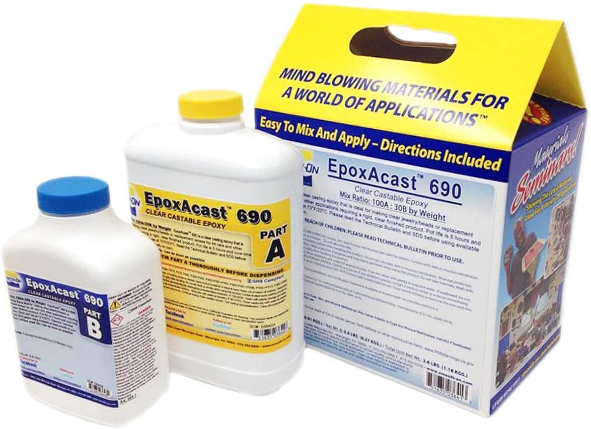
Epoxy Resin
Epoxy resin is known for its strong adhesive qualities, making it a versatile product in
many
industries. It offers resistance to heat and chemical applications, making it an ideal
product
for anyone needing a strong hold under pressure. Epoxy resin is also a durable product which
can
be used with various materials, including: wood, fabric, glass, china or metal. It is
important
to note, however; epoxy resin is not considered to be water resistant. Repeated moist or wet
conditions can cause deterioration over time which will affect durability.
Casting epoxy resins are suitable for a variety of industrial and art related projects
requiring a rigid,
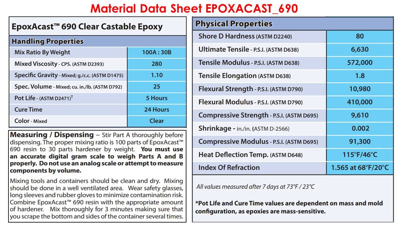
clear finished casting. It is mixed 100A:30B by weight (gram scale required) and features a
very low viscosity
for easy mixing and minimal bubble entrapment.
Details:
Clear and optically transparent with a glass clear quality.
It is a low viscous resin made specifically for casting.
Use 100 parts resin to 30 part hardener by volume (100:30) to ensure a hard finish once set.
You MUST follow the instructions accurately. Do NOT change the mixing ratio - this will
alter the properties of the resin
Stir Part A and Part B together thoroughly for at least 3 minutes.
If cured at 25 degree C this resin should be touch dry within 24hours.