11. Mechanical design, Machine design
Group assignment
- design a machine that includes mechanism+actuation+automation+application
- build the mechanical parts and operate it manually
- document the group project and your individual contribution
This week I worked on creating a claw machine! See more infomation in Fablab Taipei
My works
I responsible for mechanical structure in this project for 3 parts:
- Machine structure & decoration
- Rail system
- Claw system
Design process
Structure try and fail
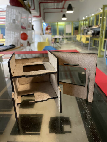
I first designed machine structure all with 3mm MDF board, if failed completely even with just small size prototype (too tight to assemble all parts, and also too fragile to carry weight when getting bigger.)
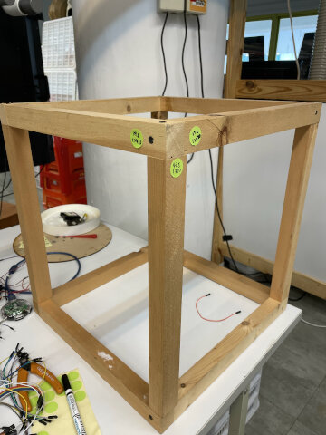
Eventually we found this wood frame in lab and use it as core frame of machine structure, and later I designed the base, wall and decorations base on it.
We named it fabgrab because we want to match the feature of claw machine (Grab) and related to Fab academy (Fab). Also we have things we fab inside and slogan Fab whatever we fab. Using Cab image Source is a funny symbol of grab lol.
Rail assemble (Level 1&2)
I started with tied to use existing rails in lab from previous project, but it doesn’t work cause the structure I made was too fragile compare to the existing one. And the X direction force cannot align with Y direction force (need to constrain all other parts which should not move)
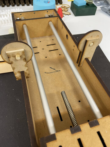
Second try with just parts and electrodrills also failed.
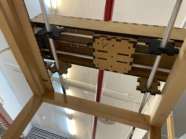
Finally with my instructor Ted’s suggestion, I started my own system design refer to Laser cut rail idea.
Claw assemble and test
Thanks to Louis (partner in Fablab Taipei), I found this MeArm claw design and refer to it, this works soon.
Mistakes and findings
Mistakes
-
Refer to the part you have, not use it directly, make a similar one: I start with thinking about the fastest way to make things work, so decide to use similar things we have in lab as parts. Such as a exsting rail (but we need 2 for X and Y). Which leads to some mismatch problem. Better refer to it and design another if not too hard.
-
Consider factors and scenarios in real world: Consider the material you are using, is it strong enough for carry weight? Or how do you going to assemble it (Such as pressfit design can be hard for the last part to fit in while assembling);
-
Doing some research first is always good: You can refer to other people’s design and know how things work. If no you may spend quite a time and design something useless because of misunderstanding mechanical force.
-
Make 3D models anyway: I did’t make a 3D assemble in fusion for these designs because of 2 reasons. First, these are for laser cut so export SVG files are enough. Second I have a plug-in in Fusion360 to export all svg file in single sketch. But it turns out that plug-in doesn’t work (and build-in export DXF fuction also export struction lines which is sucks) Maybe solution. And even laser cut should have a 3D assemble first to see if it works, also good in showing ideas to others and make it visulise. Can make all design in one sketch, extrude and use assemble function (Maybe draw in different sketch and export DXF will be easier).
Findings
-
Do spirals whatever success or failure: What I decide in the beginning is to work through each part for 1 spiral, no matter it works or not. It’s a good idea because I would’t spent too much time on one and miss the other. In this project I failed in structure and rail design in spiral 1, and after success in clae design I come back to improve them. Which is also good because the failure doesn’t feel so bad in this.
-
Using download files without parameter may cause trouble: It seems like downlaod someone’s design file and adjust a bit is a good idea. That’s how I succeed in a short time for claw design. But also be careful because those files usually don’t contain “kerf” in joint, so laser cut them directly may be a problem. I import them to Fusion360 and didn’t see “modify > change parameter” tab in the place it should be, maybe there are another way to do it and able to change parameters will solve the problem. maybe solution
Design files (for laser cut)
- Machine_structure.dxf without wood frame & decoration & control box
- rail_system.dxf you need to find stepper motors (with bar) and rail bar
- claw_design.dxf you need to find servo motor & axis (I make chopstick short as screw)
Assemble parts in 3D
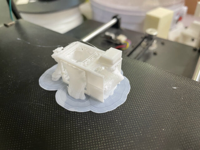
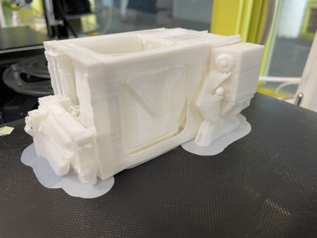
I decided to assemble them in 3D to make a small size model for my friend.
Learnings: good try to use existing models from others, servo motors and Even found lots of stepper motor model in “Insert > insert McMaster Carr component”. Also a trick is use “insert > insert mesh” to use models downloaded, and use “Mesh > Modify > Convert Mesh” to create a body from Mesh.
I also start a new design to integrate each of my design (structure, rail system, claw). To do so, output exsiting parameters and input to new design first, and copy things you need in sketch. Or a even easier way if you “just need to assemble everything in your previous project”, right click on your design log page and “insert into current design”.
When I tried to 3D print it out (originally want to make a keychain), a small one lose lots of detail, while a medium one takes lots of time but it’s hard to get rid off support. I think this kind of complicated model is not suitable for 3D print (need lots of support).