8. Embedded programming
Group assignment
- compare the performance and development workflows for other architectures
Documentation at: Fablab Taipei
Individual assignment
- read the data sheet for your microcontroller
- use your programmer to program your board to do something
- extra credit: try other programming languages and development environments
This week I worked on reading microcontroller datasheet, debugging my board and try to program it. Testing including LED blinking, LED light up when pressing, and Echo hello world.
Pre-requirement: board debugging
This week started with debt from previous week. My board still not funtioning well. I found LED suddenly lighted up when I connected it to the computer, was happy with it but soon understood it’s not normal… I did’t program it to light up!
Plus, once I changed from the converter (found later it provides 3.3V) to Arduino Uno, LED just burned itself! And I even resolder another one on it to face the same fate…
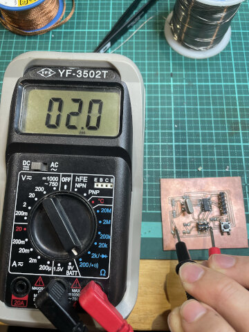
Well, the third time I used multimeter to debug carefully and thought I found the problem: the solder may accidently connected two wires that should not meet, so the ohm value shows different before and after the resistor with LED. And I resolder every of them. (Plus a crystal on my board found to be 3 pins one not 2 pins, totally wrong.)
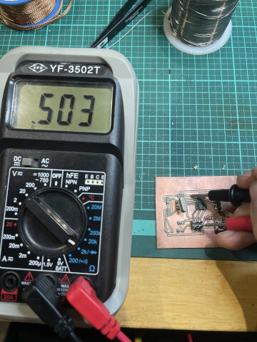
Lessons: Make sure you know what component you are using, and all wires tested with multimeter before connect to VCC/GND
But finally, it was a misunderstanding because I use “200ohm” option on multimeter to test between 510ohm resistor, so the value overpass the extreme and shows 0. Not sure what happened in the third times when Yoyo tried to help me test with multimeter, the LED light off without burned. Good news anyway!
Attiny44 datasheet
I remember this is also the assignment weeks ago, but till this week I got the necessary to read it.
First I though it would be easy because the file I downloaded only 20 pages, but later on I knew I was wrong… the completely file is about 200 pages.
Found Wiki page helps me clearify the many kinds of microcontroller. List of integrated circuit packaging types
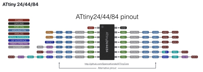
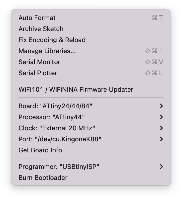
Attiny44 clock: internal 8 MHz
Press-and-lightup program (Arduino code)
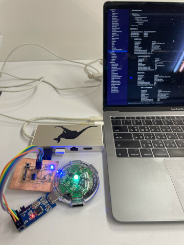
After my board seems to work, I tried to program it with my Fabisp made in week4. Connect Fabisp to the computer first, and use ISP to connect my board.
Following other students process, the Arduino IDE told me the programming successed. However the LED didn’t light up. Some trials after we changed the VCC/GND to another 5V provider, and LED lighted up suddenly!
You will also need to power the LED + Button board with an FTDI cable in case your FabIsp doesn’t supply current. Reference from Fab Tutorial Update: after weeks I found GND trace on board is broken, so the problem may because the trace is too thin to draw current passthough.
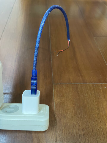
Learn 5v provider can be made with cables, just have its VCC/GND out and connect USB side with 5V adapter. Such as this one using Arduino cable and iphone adapter!
The video shows how the “press then light” program works. Just spent lots of time connecting the wire…
Also the code I used so far refer to Salman Faris. The instructions to set up Arduino inside is important. Add https://raw.githubusercontent.com/damellis/attiny/ide-1.6.x-boards-manager/package_damellis_attiny_index.json in Arduino > File > Preferences > Additional Boards Manager URLs. reference
Some said the press button and light up may use the button to connect LED, so I happen to reverse the code.
void setup()
 {
    pinMode(PA3,OUTPUT);   //set PA3 as output (LED)
    pinMode(PA2,INPUT);    //set PA2 as input (Button)
 }
 void loop()
 {
    int ButtonData = digitalRead(PA2);    //store PA2 value to ButtonData variable

    if(ButtonData == HIGH)                //check the ButtonData is HIGH (HIGH means button is pressed)
        {
            digitalWrite(PA3,HIGH);            //Turn off the PA3 (LED off)
        }
    else
        {
            digitalWrite(PA3,LOW);            //Turn on PA3 (LED on)
        }
}
Also learned
ls /Dev/tty.*command in Terminal is useful to find current port you have. (cd ~first)
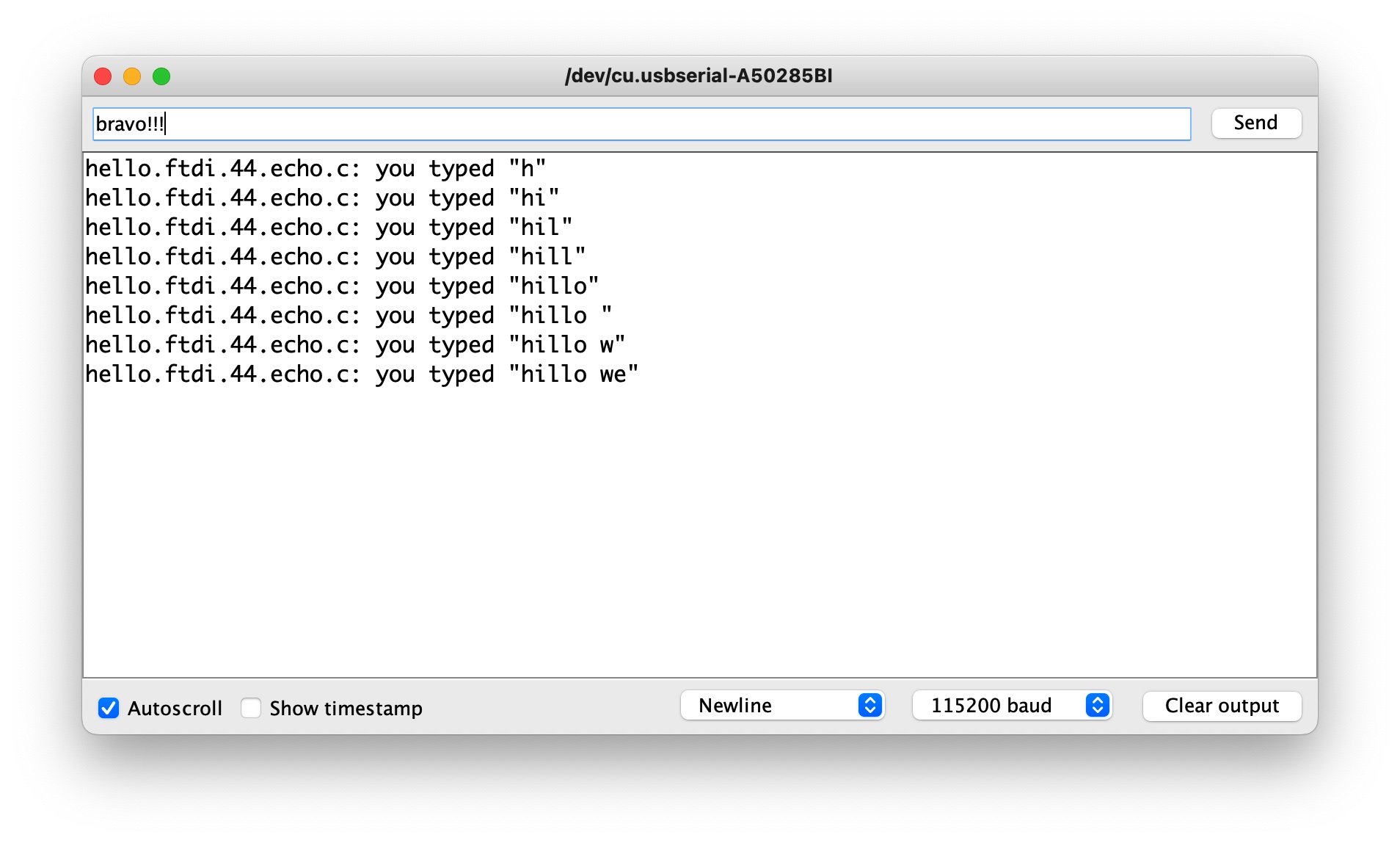
Echo-hello-world program (C code)
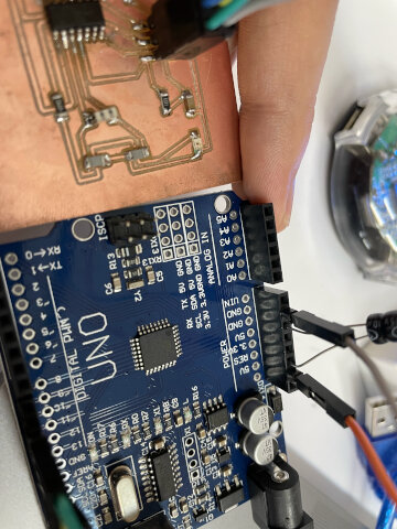
Next I’m gonna try to program C code with Professor Neil’s “Echo hello world” code. Using Arduino Duemilanove as a USB/TTL converter (Which is the only board I have at home when trying).
Have code inside microcontroller is the first step Refer to Fab Tutorial
What I learned is there are 2 parts to consider:
- Hardware/Pins
- Software/Code
My goal is to use serial monitor in Arduino IDE to communicate with my board, so Arduino board has to be a “converter”. But how?
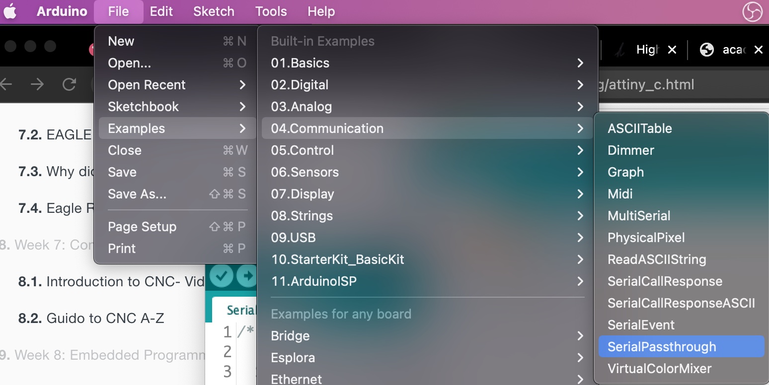
First I tried the way to connect Tx/Rx on Arduino with my board, doesn’t work. Next I got a link from instructor in Asia review, and knew the “Serial Passthrough” way, but it turns out Duemilanove doesn’t support multiple serials (can also find sample codes in arduino) reference.
So through this I got the point I need to take care of both pins and code to make Arduino board become a cnverter, then this is the link for that.
Ways to Use Arduino as USB to TTL Converter
Doesn’t need to remove ATMEL Chip (of course) or connect Reset and GND, just program the code in Arduino.
void setup(){
pinMode(0,INPUT);
pinMode(1,INPUT);
}
void loop(){
}
My screen recording:
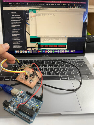
And pins connects
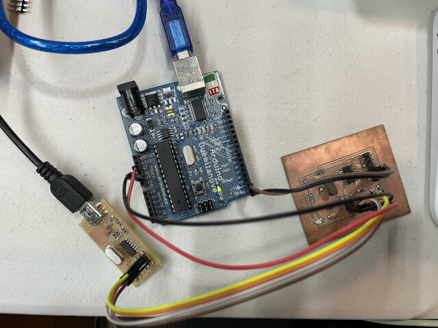
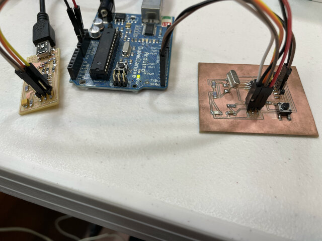
- For programming C code: Fabisp/my board - ISP connect without VCC/GND. MOSI to MOSI, RST to RST, SCK to SCK, MISO to MISO.
- For power and serial communicate: Arduino/my board - VCC to VCC, GND to GND, RX to TX, TX to RX.
And it works out like this, although still comes out jumble stuff, there’s response from my board!
Update: It works!
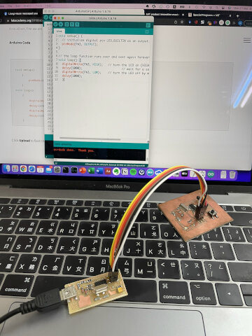
I switch to another USB/TTL converter and find the same problem, then I tried another way which is program the “echo hello world” C code direcly through Arduino IDE.
Then it works suddenly!!
but somehow when I tried later, it doesn’t works again… another hard to explain stuff
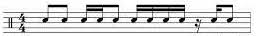
‘Rainbow clips / 11 clips’ blinking rhythm
I want to try compose some rhythm to LED flashing ways, and came up with this idea. Basically just a rhythm common in Taiwan and we use this to encourage people.
Version 2: different reaction with short press and long press
Also learn to use serial communication in Arduino code with attiny44A, reference
//  Rainbow claps / 11 claps LED blink
//  When button is pressed on the board, blink and stuff.
//  created 27 Mar 2022
//  by Heng Chang

#include <SoftwareSerial.h>
const int button = 2;   // pin PA2 on ATtiny44a
const int led = 3;      // pin PA3 on ATtiny44a
SoftwareSerial mySerial(PA1,PA0);  //define serial using (RX, TX) (need to switch sometimes)

// Define variable to use later
int buttonData = 0;
int bpm = 0;
int meter = 0;
int half_meter = 0;


void setup() {
  pinMode(led, OUTPUT); // initialize digital pin "led" as an output
  pinMode(button, INPUT); // initialize digital pin "button" as an input
  mySerial.begin(9600);  // start serial
}

void loop() {
  buttonData = digitalRead(button);   // variable for button push checking
  int mode = 0; // mode to switch from two reactions

...

// full code please download below, the page doesn't allow to show all of them
Note: something bother me quite long is that the “int” formula cannot incudes “float”. Such as
int X=(60/120)*1000, a/b = 0.5 will stop program from running. So I change it toint X=(120/120)*500and it works fine!