19. Project Development
Assignment
Complete your final project, tracking your progress:
- what tasks have been completed, and what tasks remain?
- what’s working? what’s not?
- what questions need to be resolved?
- what will happen when?
- what have you learned?
Project schedule overview
This page records my project design journal. Started from 2 weeks ago, I decided to run 1 week as “1 stage”, and at the beginning of each week I update my goal and record what I have done.
So before 6/15 (my final presentation) there are 4 stages: 5/16-22, 5/23-29, 5/30-6/5, 6/6-12.
Project overview documentation at: Final project
| Stage | Time | Goal | Spirals result |
|---|---|---|---|
| 1 | 5/16-22 | Know input/output mechanism | - |
| 2 | 5/23-29 | PCB design; programming code; build electronics prototype (sensor, Neopixels, LCD) | - |
| 3 | 5/30-6/5 | Build scorsboard & game map & magic wands & tokens; build scoreboard electronic system; integrate electronics and structure | 1 |
| 4 | 6/6-12 | Build turntable; design cards; integrate all-in-one code; acrylic decoration; wire package | 2 |
Stage 1: 5/16 - 5/22
Goal: Figure out how to use Neopixel, step response (Arduino code), and mySerial communication
First I knew my old FabISP had GND wire broken. I tried to make a new FabISP but failed… cannot figure out why. So I used the ISP programmer in lab and finally figure out to choose “USBasp” as programmer (It shows as USBasp in USB list to hint?)
Note: Using USBasp doesn’t need to select port, if choosing one and you will get error. Just keep it empty and press arrow to upload or
sketch > upload. reference
Then I did some research about neopixel, and found that it’s actually Adafruit’s branding of a few identical LED chips named WS2812, WS2811 and SK6812 respectively. (reference). So I found a ws2812 LED strip online and go buy it in store (ws2812 use 5v as supply).
Then I watched 2 videos to understand how to setup Neopixel. This instructables article is really helpful. And this one also shows you the connection and the “extra 2 wires” usually come with LED strip are spare VCC/GND. Again a Tinkercad simulation shows the rainbow effect.
In summary, just use Adafruit_NeoPixel Library for Arduino. I’m going to use “theaterChaseRainbow” funtion in Strandtest example and modify it. One thing to keep in mind is that after you give commands to LEDs, remember to show so you can see the commands work.
strip.clear();         //   Set all pixels in RAM to 0 (off)
strip.show();                // Update strip with new contents
Next I google diy cooper tape sensor and found this article. It explains many stuff but some links are missing and have some mistake in code. It’s using CapacitiveSensor Library and this official site contains a explanation video and sample codes.
This website is easier to understand. According to it, I need those thing to absorb current and become sensor: 2 digital pins and (at leeast) 1 1M resistor for each sensor.
Lastly I go back to test wired serial communication between projects with SoftwareSerial Library and even some tips for open 2 serial monitor at the same time on Mac. Documentation in Fablab Taipei site.
Extra links from Asia review: Communication between Arduino using I2C (CH); Networking and communications assignment from Kurumi.
Reflection questions
- Tasks completed?
- Get Neopixel LED strings
- Tasks remain?
- All design and fabrication
- What’s working?
- Neopixel test
- CapacitiveSensor test
- SoftwareSerial test
- What not working and need to be resolved?
- New FabISP doesn’t work
- What have I learned?
- How commercial ISP programmer works
- How to setup Neopixel
- HOw to setup CapacitiveSensor
Stage 2: 5/23 - 5/29
Gaol: Board design, programming code and get prototype with all sensors and neopixel works
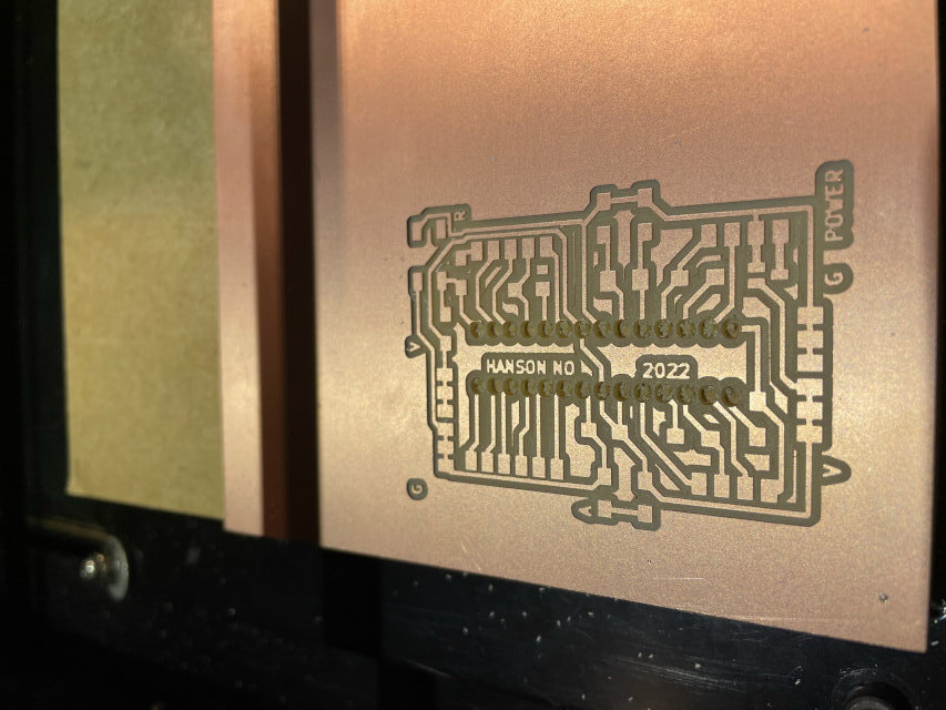
Because I started all testing with Arduino, Ted gave me a nice suggestion that I can make a board using Atmega328P(the one on Arduino Uno board) to make a board. Once makeing sure everything works fine on Arduino, I can relieve microcontroller from socket and put it on my board!
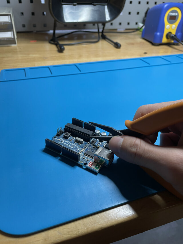
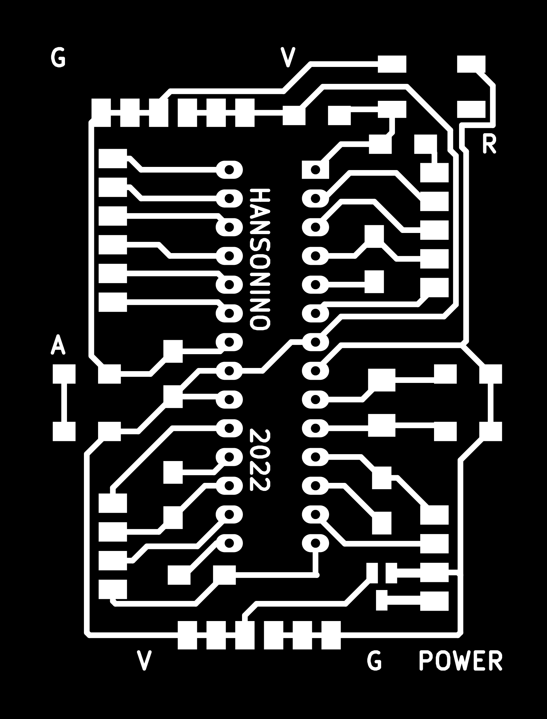
Searching on the net for DIY Arduino board, and I realized they are either too complicated, without design files or don’t satisfy my needs. Finally I refer to Neil’s hello.arduino board(with many links) and pin mapping to design my board.
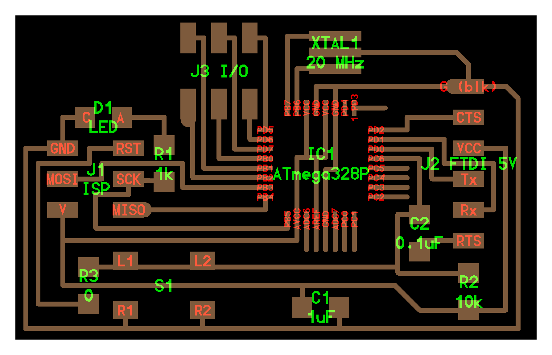
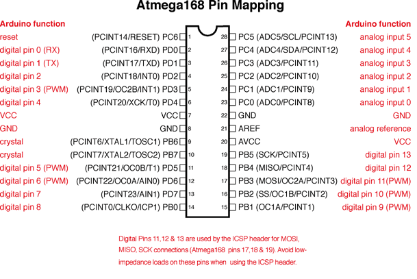
2 things to keep in mind before starting: first is the Atmega328P on PCB design must be flipped because we are using through-hole socket with single-sided copper FR1 (or it will be hard to solder between socket and FR1); Second is the crystal should use 16mhz the same as Arduino UNO to make sure speed keep the same. (together with 22 pf capacitor and should flipped as well if using through-hole one)
Pin requirements: 16 digital, 2 analog, 6 VCC, 1 Vin, 7 GND.
- 4 sensors: 8 digital pins (4 inputs, 2 digital pins for each) update: actually can use only 5 digital pins, 4 sensor pin and 1 reference pin
- Communication with / supply power to another board: 2 digital pins, 1 VCC, 1 GND
- 4 leds (neopixel): 4 digital pins, 4 VCC, 4 GND update: using series connection only cost 1 digital pns, 1 VCC, 1 GND
- OLED: 2 analog pins, 1 VCC, 1 GND
- Power supply / reset: 1 RESET, 1 Vin, 1 GND
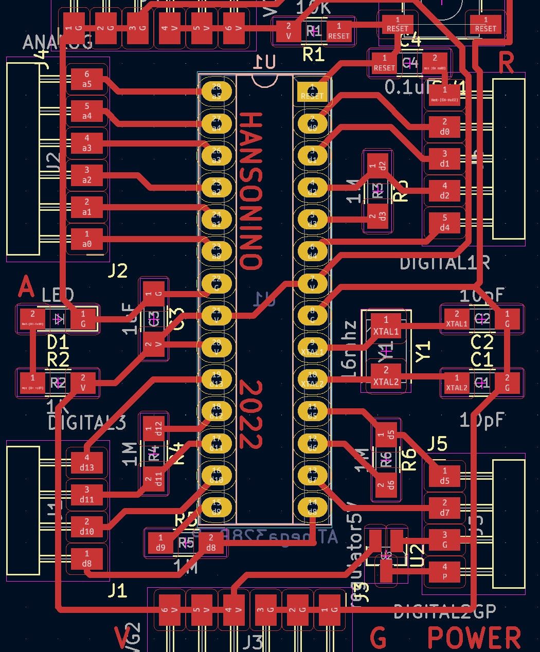
Thus I used all digital pins and get 4 analog pins left. Another thing to record is about through hole (TH). This time I’m using TH package microcontroller, so the question is how to mill these holes?
I found these holes are in layer ‘F Mask’ (front) or ‘B Mask’ (Back because I flip microcontroller) in Kicad. So first way is to export svg including this layer. Or another way is open ‘F_cu’ (traces) layer in illustrator, and you can find these holes in WHITE. So just delete traces and turn these holes into BLACK!
Difference between these 2 ways is: using ‘MASK’ layer including copper surrounding holes so it will be bigger. And if your endmill is smaller than this that may be a problem. While holes in ‘F_cu’ layer is actually size of hole.
Edit footprint: Click each hole footprint and press ‘e’ to edit its size (can only fo it one by one?), or right click the whole component and choose ‘properties’ change footprint in library.
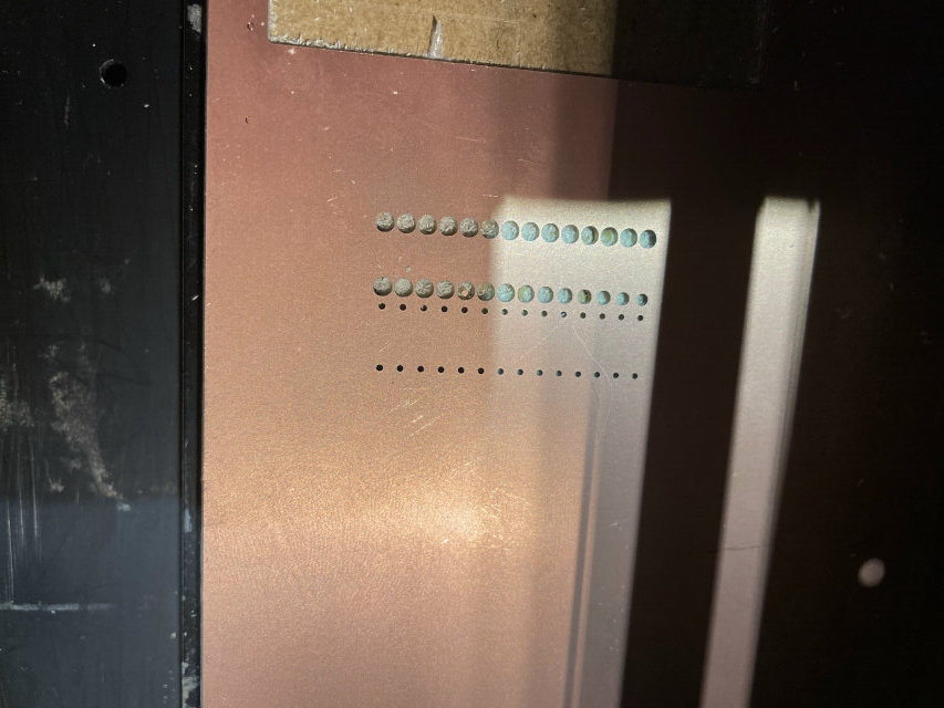
Next important stuff is when using 1/32 endmill (cut out board) to mill holes, I made a mistake to invert colors and the holes become so big and mess up! So these are the right color set for milling! (Not yet try to combine through holes and edge cut together)
Pin header design tip: if you are using male pin header, make distance shorter and add mounting holes may help them be more stable; if you are using female pin socket, make distance longer (even longer than socket) or even stick them on board usig some ways.

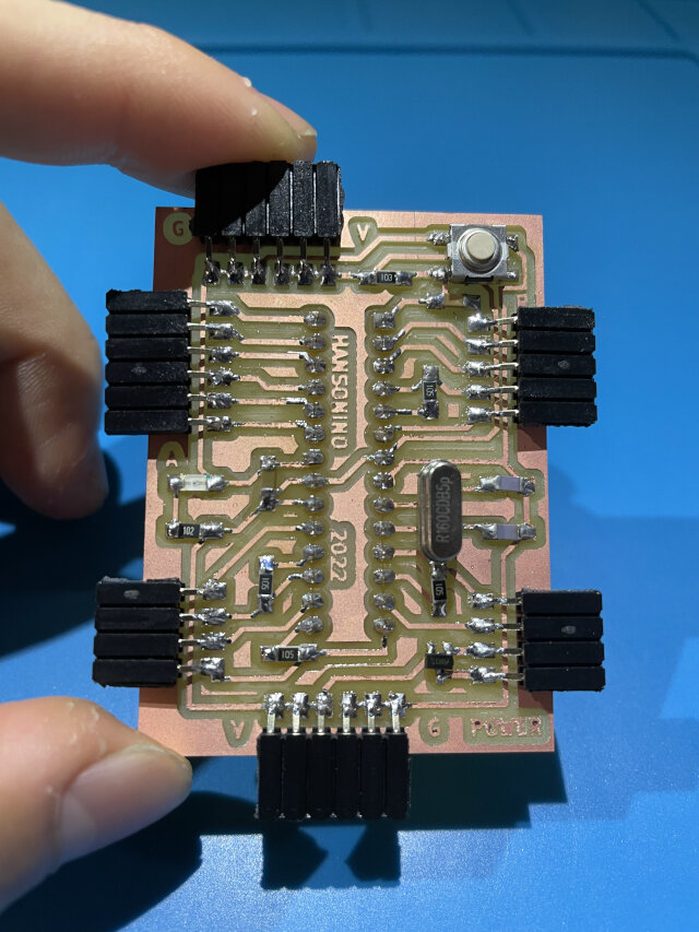
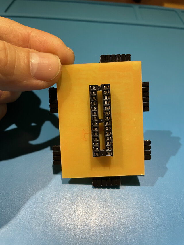
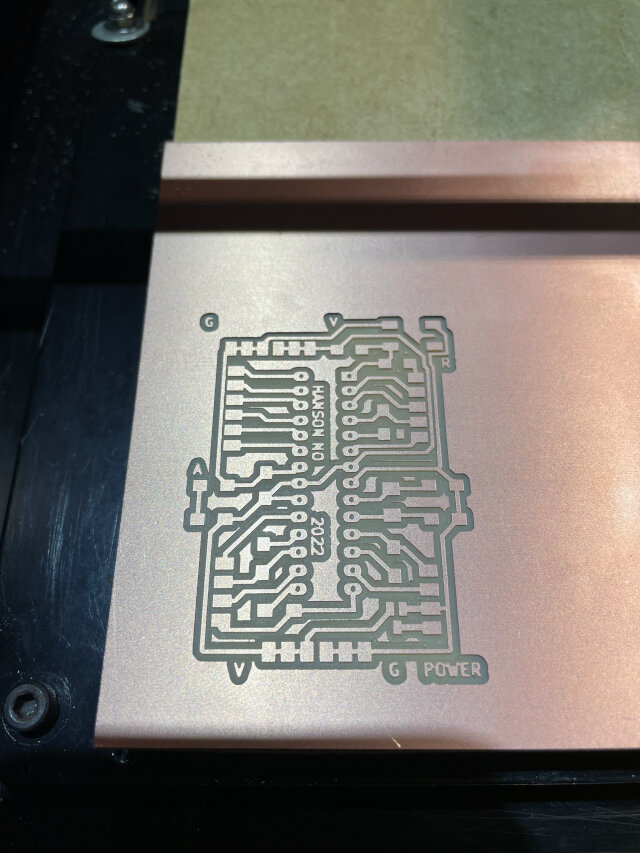
Then I test my Hansonino with those sensors and Neopixel, it works!
I encountered a issue that
Serial.print()from Hansonino doesn’t work, serial monitor kept receiving nonsense charactor and even every time I press the sensor these’s something print out (I didn’t have that in code!). Because I changed Neil’s 20mhz to 16mhz, I thought it might be a problem of clock speed, and found DIY Arduino Sketch example said using 22pF capacitor for 16 mhz crystal, and also this thread did mention capacitor value matters for crystal. And after changed 10pF to 22pF capacitor it works fine!
I later encountered something weird that my Attiny45 board made in week14 cannot control Neopixel strip correctly, when pixel numbers go from 25 to 26, Neopixel strip just stop responding. And later I also saw error message in Arduino IDE said error:sketch too big so maybe attiny45 is not a good option for control many Neopixels (library) and I used another Arduino Uno to replace it and works fine!
Even though attiny45 cannot support my ptoject, I still learned something important about it. First is you need to assign pin “3” instead of “PB3” (for example) in Arduino code. Second is you (probably) need to connect a small (220ohm) resistor between attiny and neopixel strip’s data wire refer to some sites. Third is when one board print(”14”) in serial, another board’s code read == ‘1’ and read == ‘4’ will both be triggered.
Note: if still using attiny45 to control Neopixel, can refer to this site. It tolds you how to connect wires with resistor. And this thread tells memory limit for attiny45.
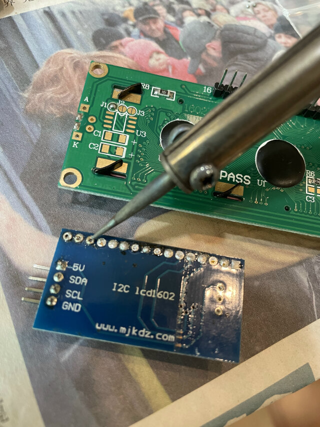
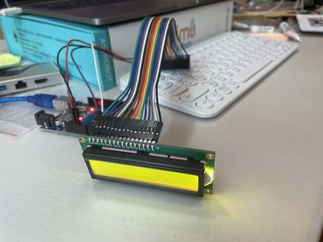
Extra: this week I decide to use a LCD (with I2C adapter board) as user interface, so I found one from my previous work, and quick study for its code. These 2 sites explain about LiquidCrystal_I2C library and Wire library.
Using LCD gives me a user interface to show game status: to set game duration and show winning moment! To set game duration, I again using those magic sensor as selection keys and the way to confirm it. (Note: If using attiny, this site mentioned how to use I2C connection.)
Also find it helpful to have more VCC/GND pins on Arduino Uno without using bread board (Using “ICSP” pins) reference
Reflection questions
- Tasks completed?
- PCB design (for game map)
- Electronic components prepared (BOM list)
- PCB milling and soldering
- Codes for integrating sensors, Neopixel LEDs and LCD
- Tasks remain?
- Laser cut: Game map, scoreboard
- 3D print: tokens
- PCB design: scoreboard
- Integrate electronics and structure
- What’s working?
- Using sensor to trigger Neopixel (using Hansonino)
- Sensor correctly pairing with corresponding Neopixel LED
- All input and output system testing (sensor, LED, LEC)
- What not working and need to be resolved?
- Fail to mill through hole on FR1 correctly (solved)
- Hansonino had communicate issue with Serial (solved)
- Attiny45 doesn’t has enough memory to drive too many Neopixel LEDs (replaced with Arduino Uno)
- What have I learned?
- Crystal should be paired with specific value capacitors
- Calculate pin requirement and memory requirement first to choose a proper microcontroller
- How to mill through-hole footprint (design by Kicad)
- How to setup I2C LCD
Stage 3: 5/30 - 6/5
Goal: integrate eletronics & structure prototype (delay); second PCB on scoreboard, solid game map / magic wand structure, player board, decorations (acrylic cover on LED)
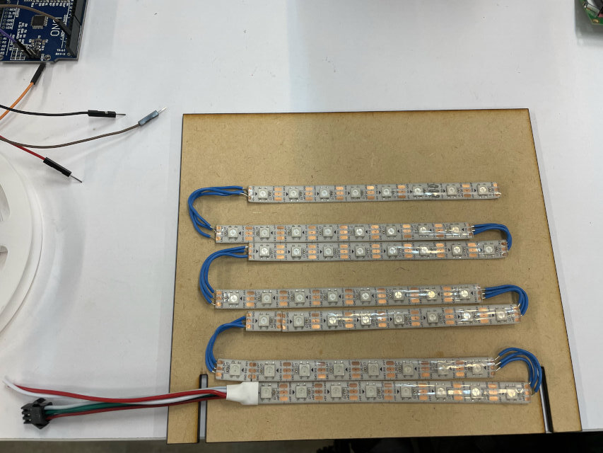
So last week I didn’t finish my prototype as schedule, only have all electronic parts set. And this week I started laser cutting scoreboard & game map. And also try soldering Neopixel strip in order on scoreboard, which is quite challenging…
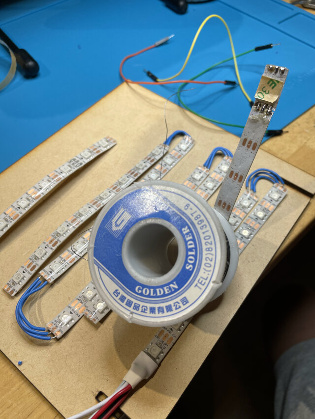
I use line with single core (solid conductors) but found this kind is too tough. In many times it just detached from Noepixel even with copper on it! I have to get another Neopixel to replace the one without copper. Next time use a softer line (stranded conductors) for connecting different strips that with 180 degree angle.
Next I found my magic wand with copper tape on front end cannot sense well, but when using another much bigger copper it does! Later using Arduino serial monitor, I knew it did increase the value received but is too small and can also lead to occasional mistakes. So I decide to extend the copper to the whole magic wand and thus our finger can be a current absorber and massively increase value received.
I tried again using our big vinyl cutter to cut, but somehow the machine doesn’t work even I restart everything. (previous it show error in my Mac but still cut out) Then I found this thread says the reason may be the baud rate setting between laptop firmware and machine. But cannot find this setting in Windows for Mac.
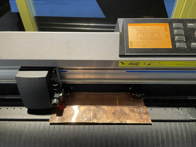
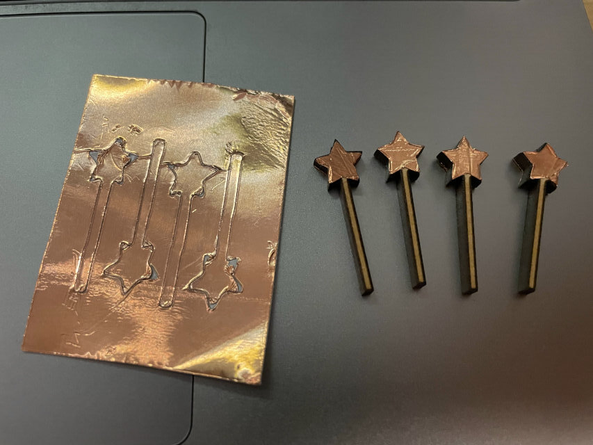
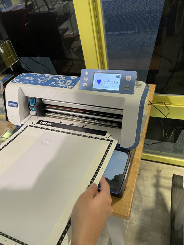
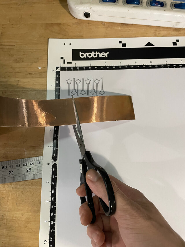
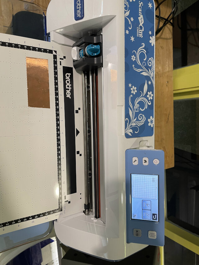
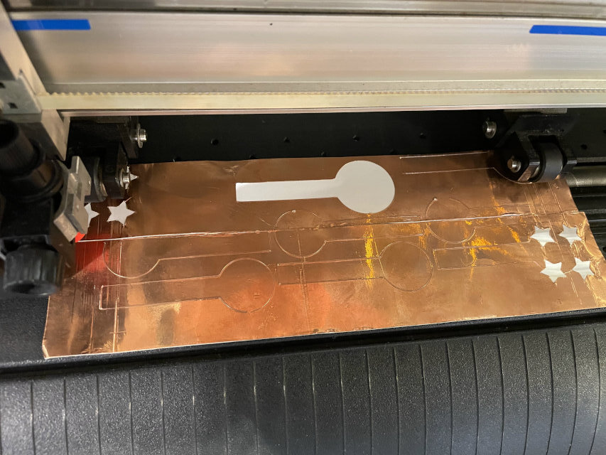
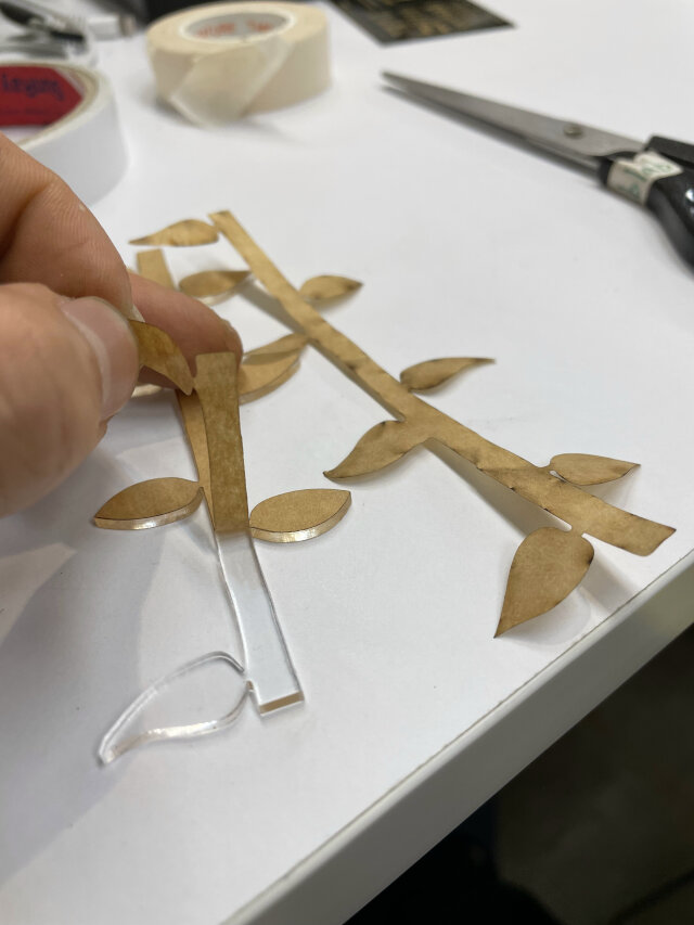
Later with Jimmy’s help, I tried another scan & cutting machine from Brothers. I printed out my magic wand on A4 paper and stick it on another grid paper, and then the machine will scan it and saved data. Next I take away A4 paper and stick copper on the right position of grid paper, and machine will cut it out!
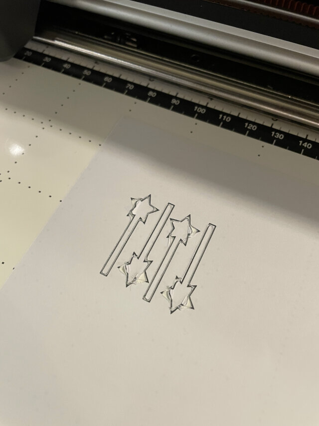
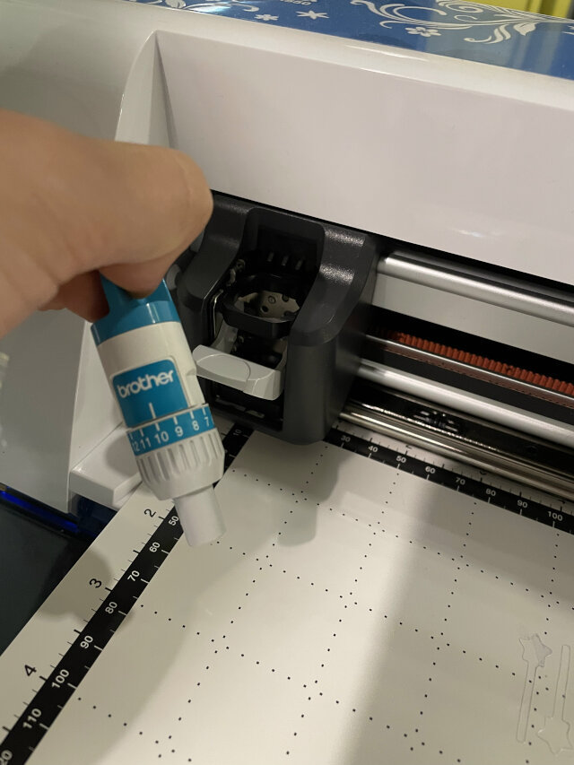
Note: First is adjust the depth of blade (just get blade off and rotate form 1(shallow) to 12(deep), and copper tape use 1.5). Otherwise it may cut nothing or harm grid paper underneath; Second is reading svg file from USB also works, but somehow the cutting result is smaller than my original design…
Scan & cutt machine usage
first prepare a special grid paper (in the box under the table, and for this machine only) and see if it’s still sticky. If not, need to use some kind of spray to make it sticky refer to Jimmy.
-
Scan & cut
- print out your design from another printer, and stick A4 paper on the grid paper
- press a button to get grid paper in, and press another button to scan
- when grid paper comes out, take away A4 paper and cover your target material on corresponding area of grid paper(such as copper tape). You can use scales showed in the image to align with grid paper.
- Get blade off from machine, adjust number scale on knife, 1 is most shallow and 12 is deepest.
- choose the right scan image in machine, press a button to get grid paper in, and then press cut.
-
USB import & cut (Result will be smaller)
- insert USB with your design in svg file, find it in machine
- cover your target material on corresponding area of grid paper(such as copper tape). You can use scales showed in the image to align with grid paper.
- Get blade off from machine, adjust number scale on knife, 1 is most shallow and 12 is deepest.
- press button to get grid paper in, and then press cut.
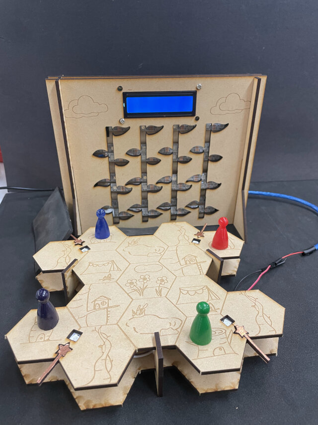
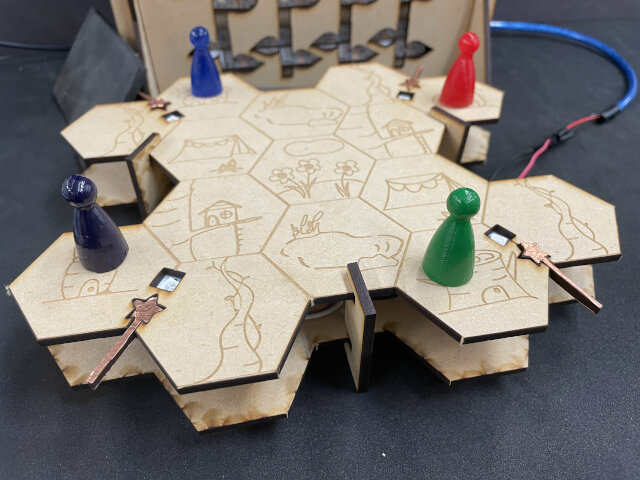
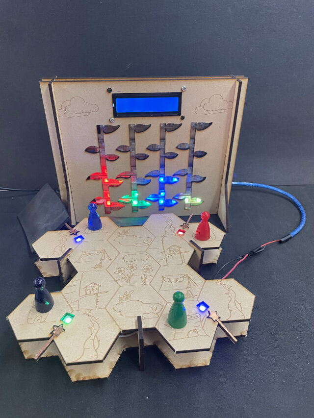
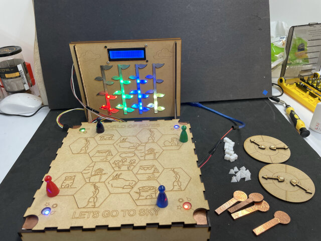
Lastly I rewrite the code for scoreboard according to the order of Neopixels to show each beanstalk growing. (like a math challenge!) And finally get everythiing done but still have few problems:
- Too many wires and Arduino Uno can be seen and looks mess. Will try remake structure to contain wires, and even reduce the number of wires (at least hide it behind).
- You can see LEDs directly and it’s ugly… tried transparent acrylic but it’s not good enough. Maybe try colored acrylic next.
- Senser isn’t stable because there’s no support under them. Also the “star” shape has too many curves and often stuck wand when sensing. Will try again with easier shape like “circle”, and build a solid MDF support under.
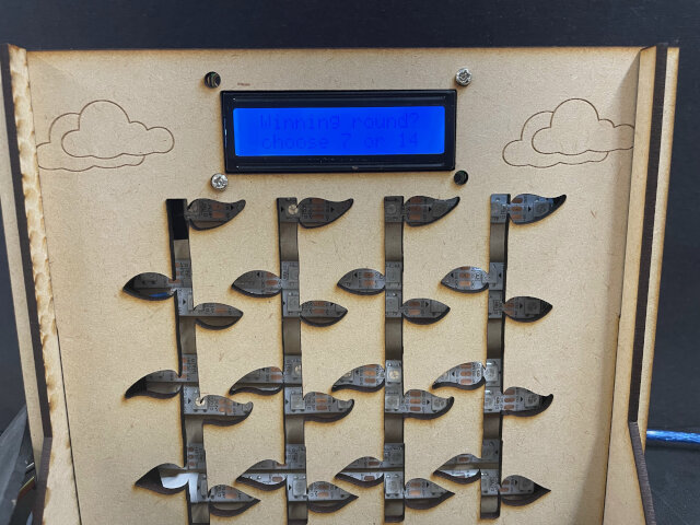
- LCD screen always have some problem. sometimes has no words, sometimes ther are nonsense characters, or even just nothing. And the newest problem is cannot clearly read words on it because the clolor is too dim(even adjust resistor behind) while nonsense character is very clear. Update: problem may be the connection of Atmega328P and its socket, the pins are not connected well
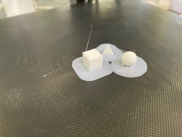
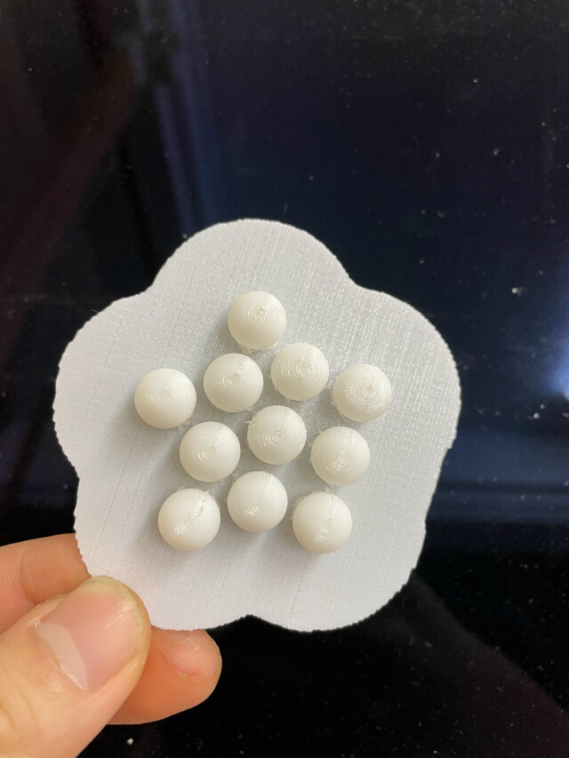
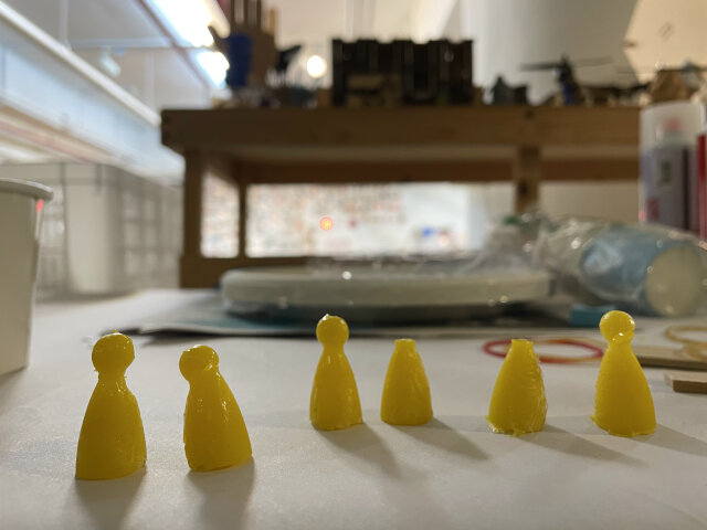
At spare time I also 3d print some simple tokens as energy indicators in game, including circle, triangle, square shape.
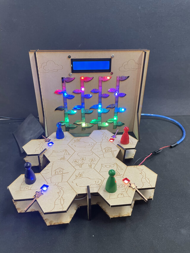
Spiral1 result!
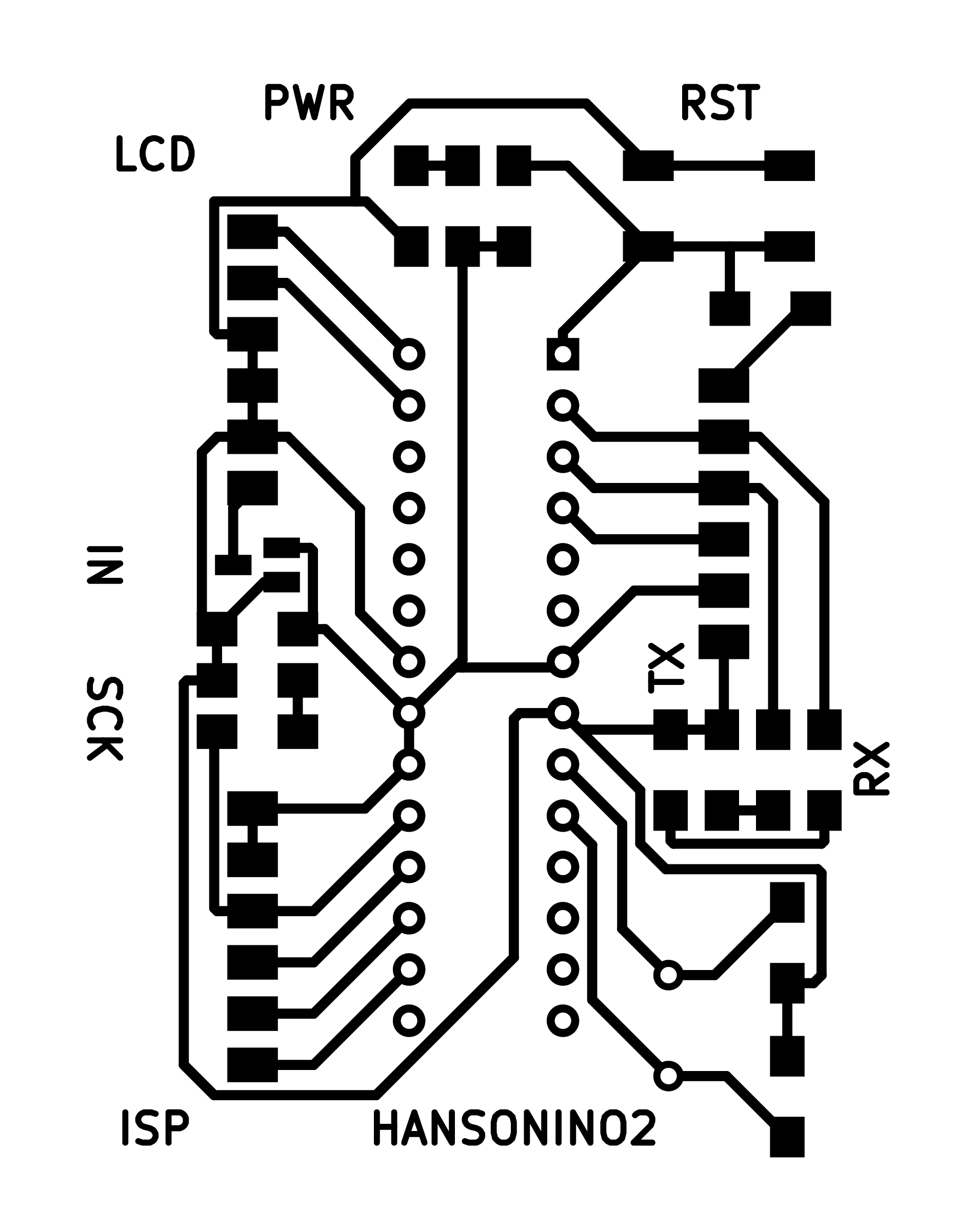
Spiral2 starts with another PCB design, my plan was to put it on scoreboard to control LCD and neopixel string. So only have these pins functions:
- d2, d10: digital pins
- TX, RX: serial communication
- a4, a5: I2C
- rst, d11, d12, d13: ISP
I tried to add some LEDs in RX, TX and sck (d13) to help observe data sending/receiving because that’s the visual way to debug. And ISP is used as a backup way to programming in case doesn’t have a programmer nearby.
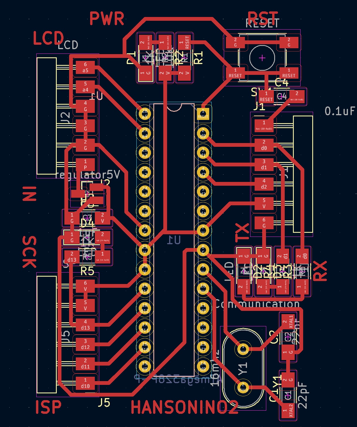

But unfortunately when milling I broke my 1/64 trace cut endmills twice! And I found the reason is the joint to connect motor and spindle became loose (it happened before). So I used another joint made with 3D print before to replace the older one, but it’s too tight to fit in. So I use motor as a drill to screw it in, and it works initially but later stuck on the half way to fit in perfectly. When I tried to put spindle on and turn the motor on, it suddenly freezed and the motor just stop responding anymore…
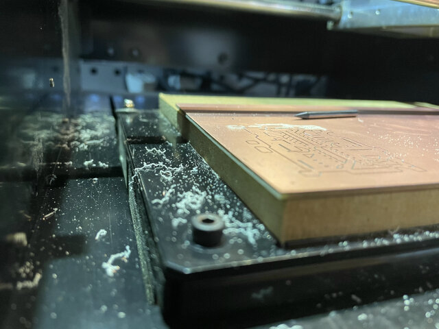
Sadly I decided to let it go for now to save time. That’s what I learned from machine design week: just keep going and do what I can do, when finish the rest and then come back to it, that’s what spiral design means.
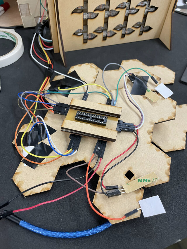
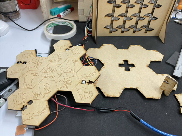
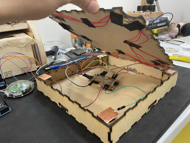
My next plan is redesign game map. I started the idea with making a simple box. The surface of it is game map, and PCB and all wires can be inside. A little work did first is stick some piece of board under PCB to make it stable (it’s not horizontal because the Atmega328P socket beneath).
Since only a simple box is needed, I don’t want to take too much time to design myself. This site introduce many resources to generate laser cut box. I used MakerCase before but failed because without setting kerf successfully. And this time I found a article introduce how to solve kerf issue in MakerCase! Only draw a 10mm square and cut out, then use caliper to measure the kerf and set in MakerCase.
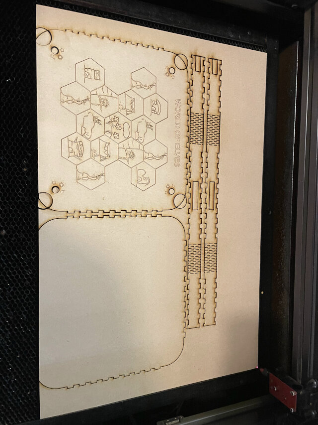
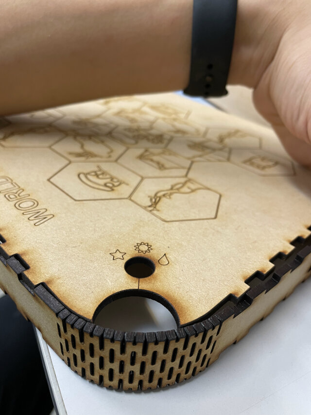
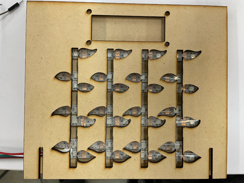
With this information I successfully make a press fit box. But when I want to make kerf bent box, it just doesn’t fit (cannot bend enough), So I make a square box instead. I left some space on 4 corners to be magic sensor area, and the shape is round to make it easier to sense (the star shape before looks good but always stuck).
For some reason my Illustrator cannot oprn dxf file downloaded from MakerCase, so simply choose svg file to download.
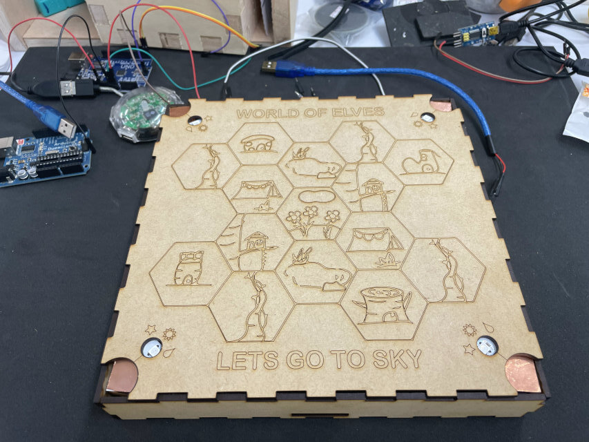
To make sensor area stronger, I simply make 4 tiny boxes (sensor boxes)inside and just reach the top of big box. Stick copper tape on them and connect with PCB. About magic indicator LEDs on map, I resolder them in series (Neopixels can be strip) and thus only use 3 pins on PCB (1 digital pin, 1 VCC, 1 GND). But I forget to left tunnel on side of box for wires to go out, do it again and solve the problem.
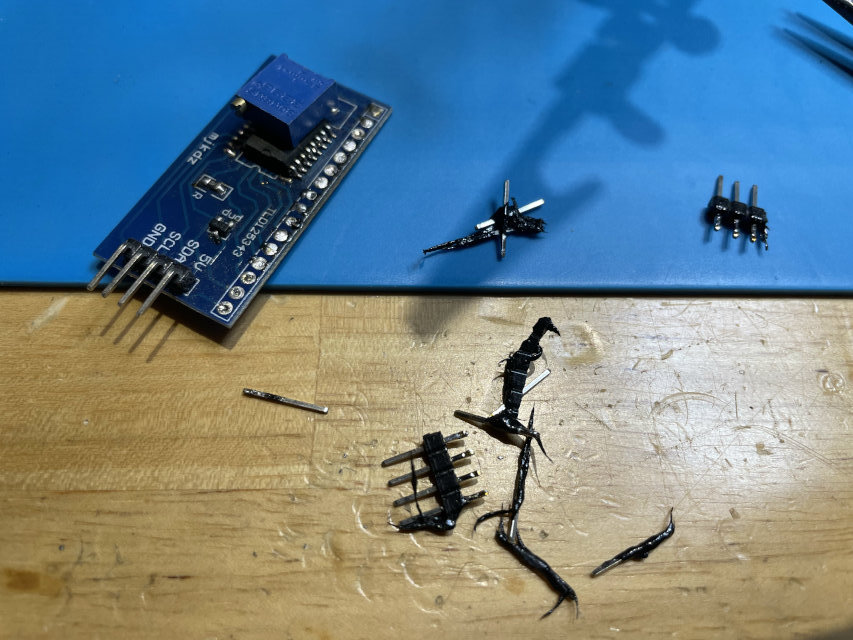
Also I found some LCD screens with its I2C adapter in lab, but somehow both of them have pins soldered on it (then how to solder together?) so I use hot air gun to desolder them but even melt platic on it, which is quite disgusting. But later found that I should do some testing first. Connecting those pins with dupont wires and program example code in Arduino, it doesn’t show words on screen. I suppose the potentiometer on adapter is broken because there’s no limit for spinning.
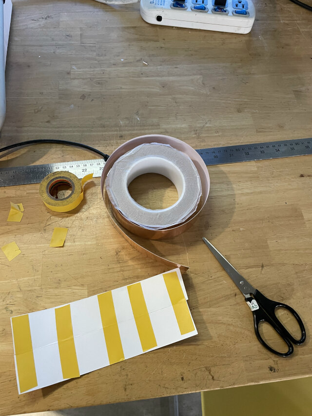
Good news is that I tried with bigger vinyl cutter in lab and it works again! Maybe last time my cable was broken. Again use tape to stick 2 pieces of copper tapes to “cheat” cutter it’s a paper (which is big enough). And also understand that vertical pattern on computer will become horizontal while print out : )
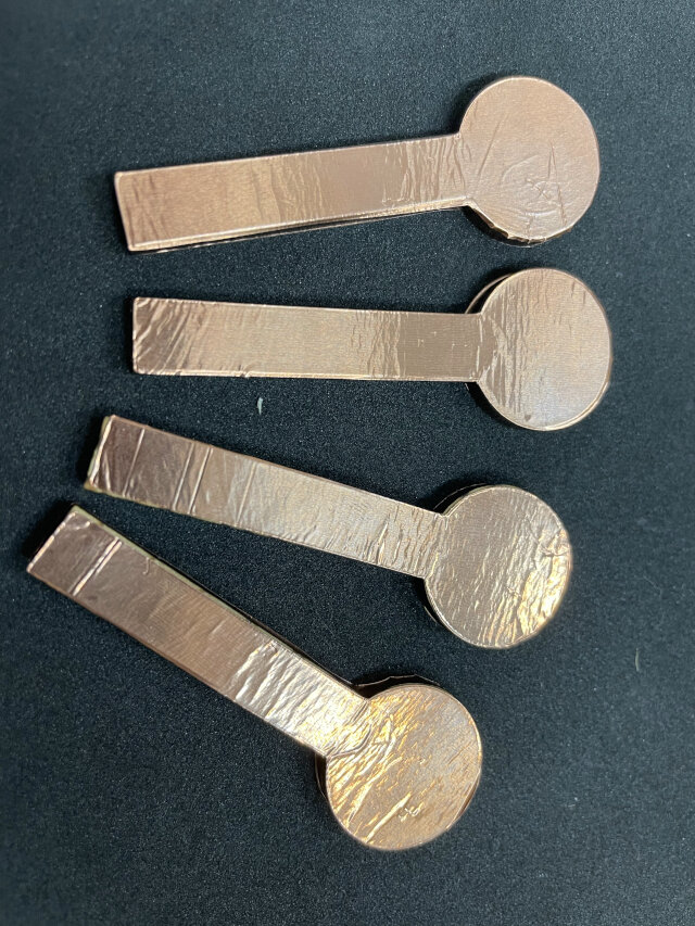
Successfully have my new version of magic wand (general but practical). Actually 2 versions: one with MDF board, another with acrylic. Both covered with copper tape.
Lastly I also tried different code exampple from CapacitiveSensor website, the “threshold” (sensor being touched, stop reading and recalibrate) one. But somehow it kepts triggering itself and has no idea why. So just change the code back first.
Reflection questions
- Tasks completed?
- Install Neopixel strips on scoreboard
- Scoreboard design, game map redesign
- Laser cut scoreboard, game map, and magic wand (3 versions)
- Vinyl cut copper tape (2 versions)
- Update code for showing each beanstalk growing
- PCB design for scoreboard
- Sppareate codes for game map, scoreboard
- Tasks remain?
- Design & create pepherials (player turntable, cards)
- Packaging for wires and PCB
- Decorations for Neopixel LEDs
- Video and slide
- What’s working?
- Using magic wand to sense
- Each beanstalk growing correctly in order by sensing
- What not working and need to be resolved?
- magic wand cannot sense correctly (solve by conduct electricity to finger)
- Vinyl cutter not working (instead of using another machine, and later find it works)
- LCD screen always have probelm to show correctly, and spare one doesn’t even work when testing
- CNC stop working and fail to fabricate PCB
- Try “CapacitiveSensor” code with threshold but failed
- What have I learned?
- How to use scan and cutting machine
- Add LEDs on PCB to visualize signal pass through
- Use online tool and adjust laser kerf to successfully assemble box
- When designing gimmick, condiser curves of the shape to make it works easier
- Remember to left tunnel for wires in structure
- Try to dcrease the number of wires as possible
- How to “cheat” vinyl cutter to cut copper taper (as paper)
Stage 4: 6/6 - 6/12
Goal: Design & create pepherials (player turntable, cards), decorations using acrylic and pachage wires, integrate things to make slide and video
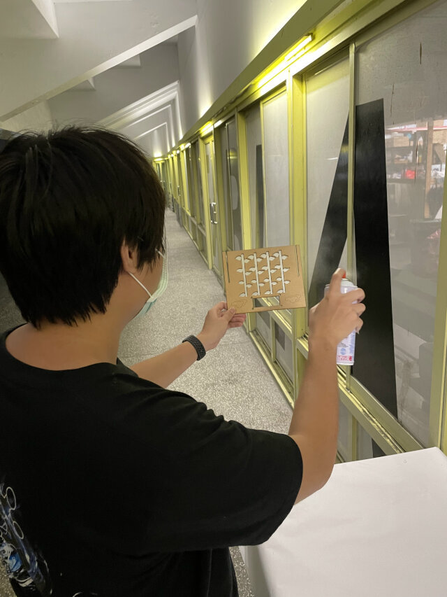
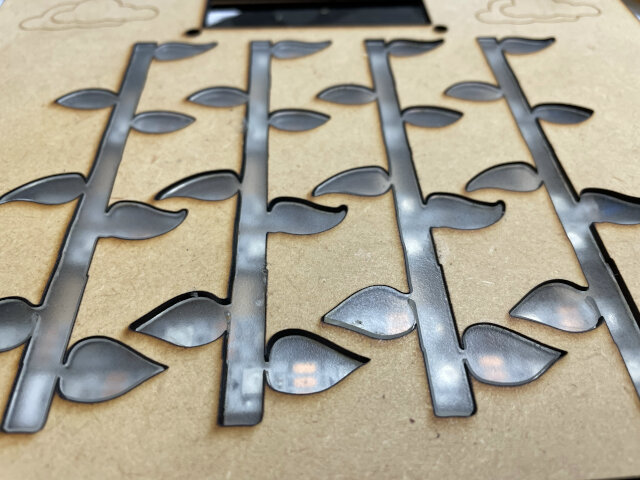
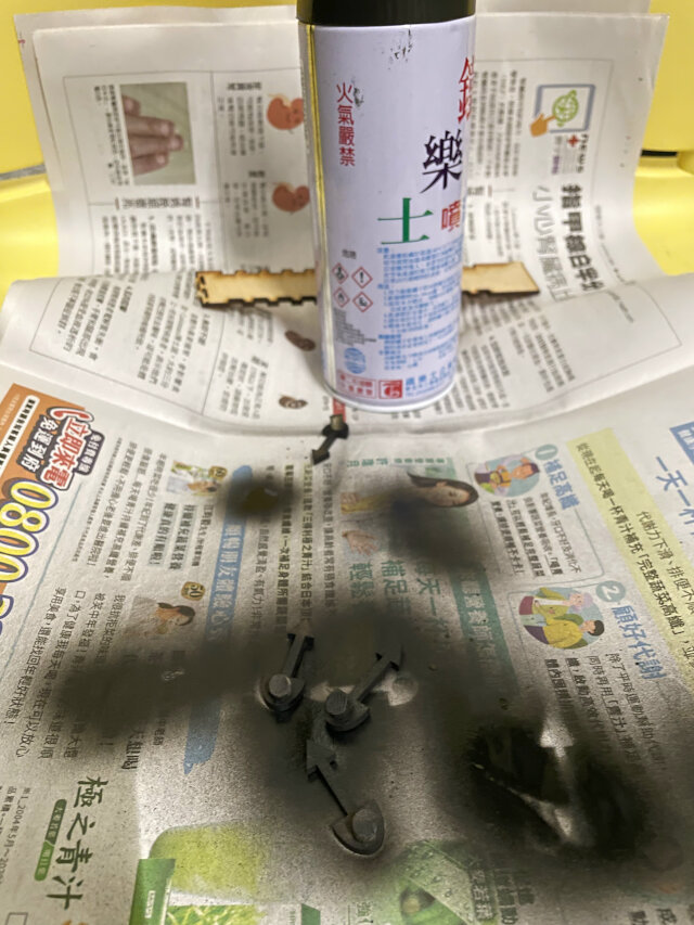
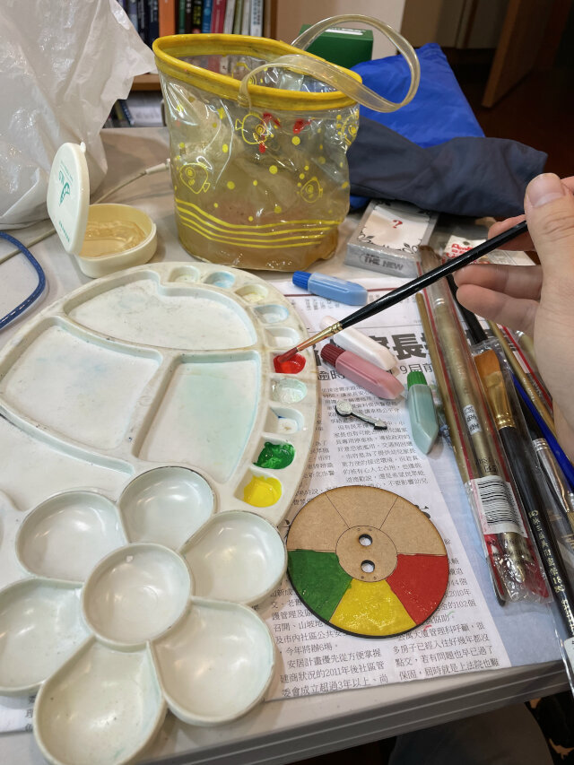
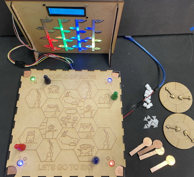
This week I started to play with spray and paintings. With jimmy’s help again, I found a transparent spray in lab and turn the surface of acrylic for transparent to matt. And then use white glue to stick them on MDF board. Therefore, player cannot see LEDs direcly because it looks blur.
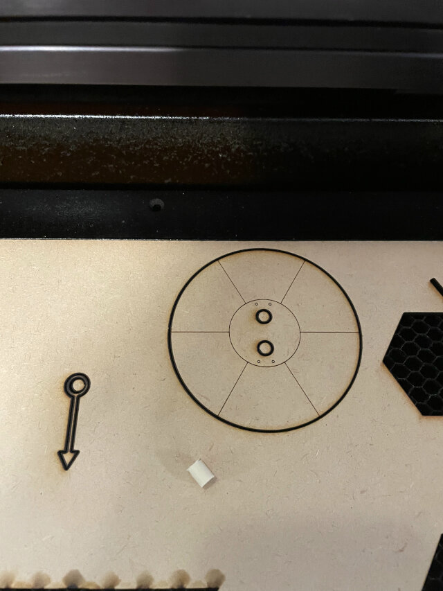
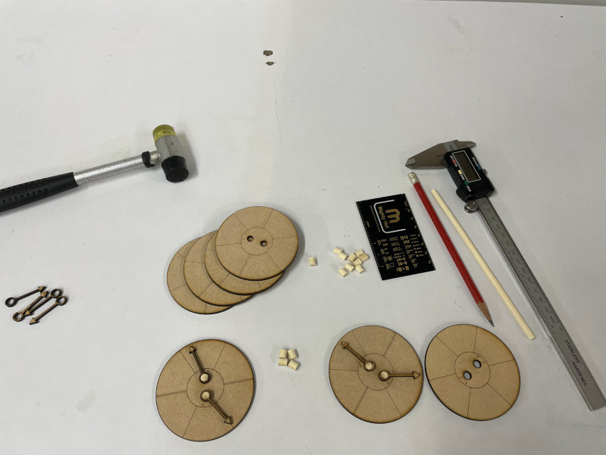
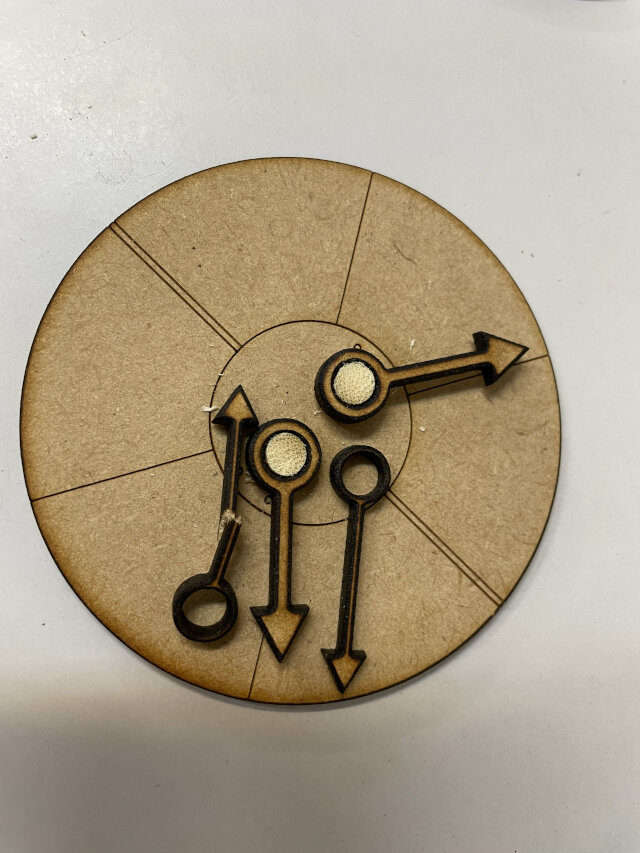
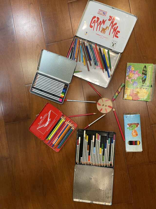
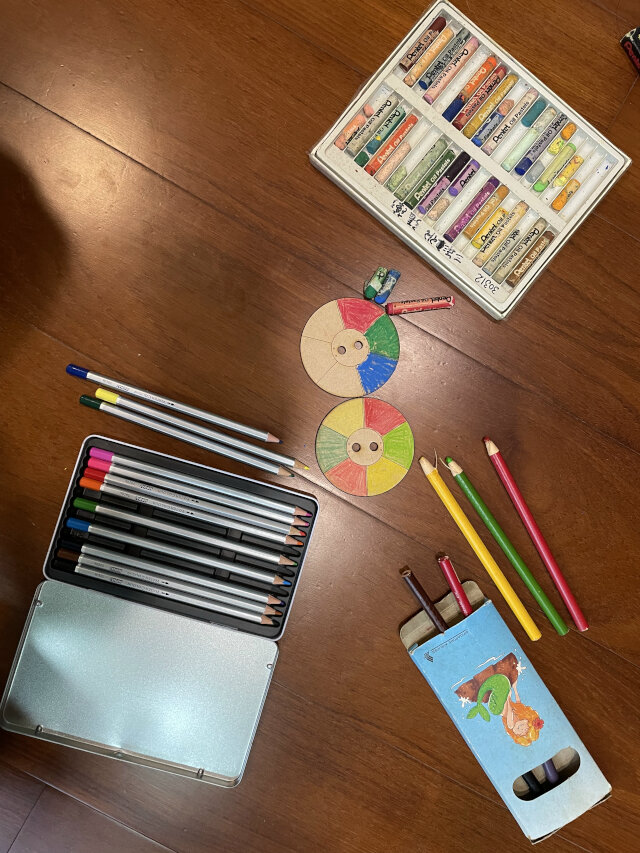
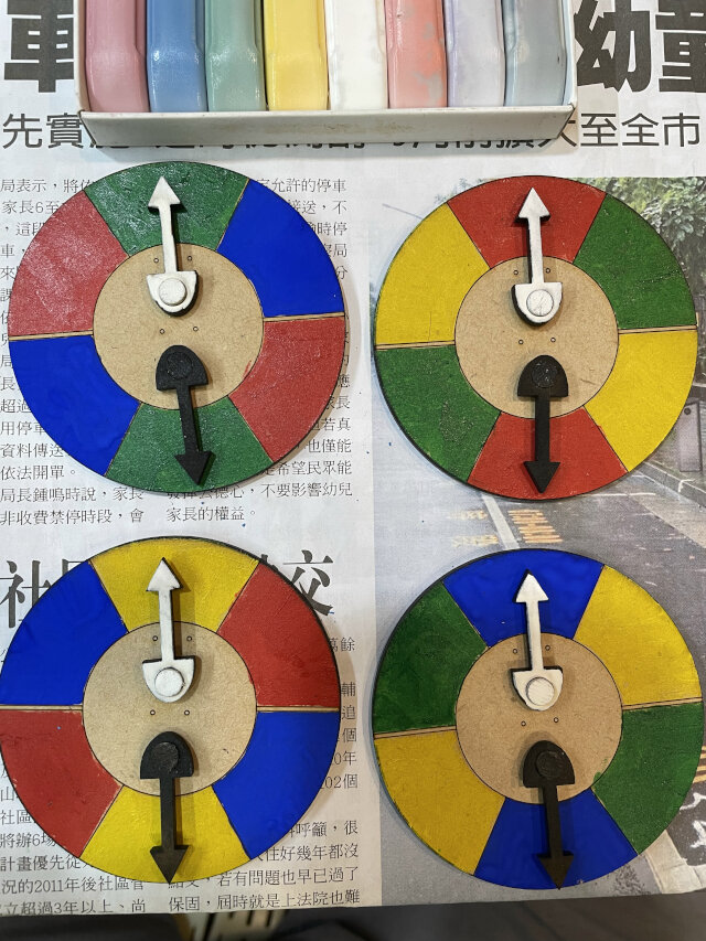
I design the turntable like a clock to show relationship with other player. The shape of needle looks like a mouth, and togther with dots (eyes) on MDF board, you can tell it’s wither smile or angry face. I used chopstick as axis and laser cut MDF, and then paint the board with spray and watercolor.
And I cast the yellow chessman (player indicator) that I didn’t have yet. But somehow the resin already fix even without adding hardening agent… which leads to terrible outcome (later buy another can of resin and works). I also combine 2 codes for map and scoreboard to be an all-in-one code(without another Atmage328P board) and that works! I also found that the box of game map has potential to package everything inside, and make the game easier to bring out ~
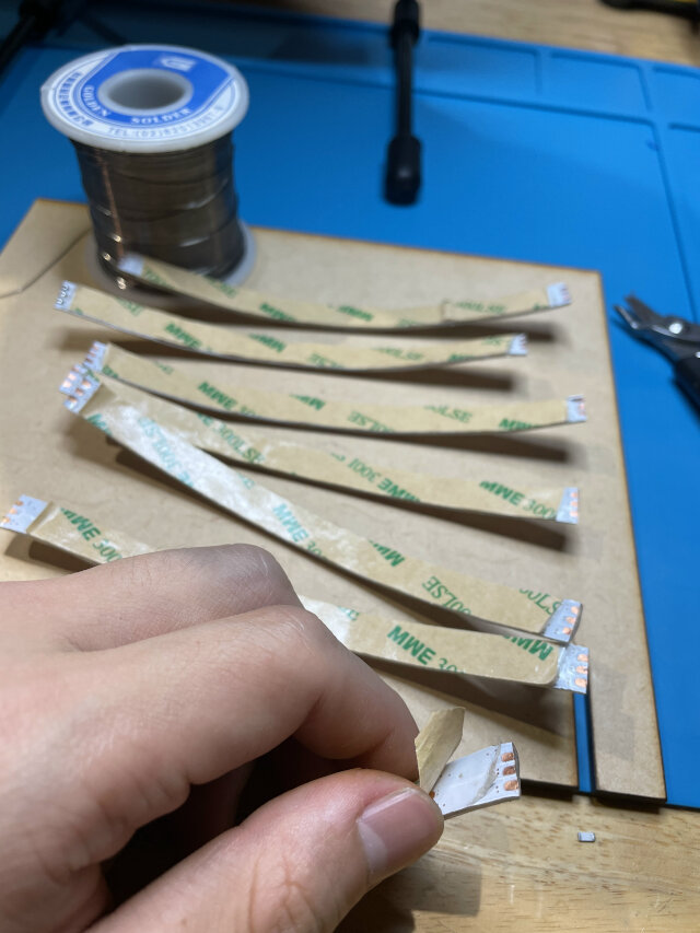
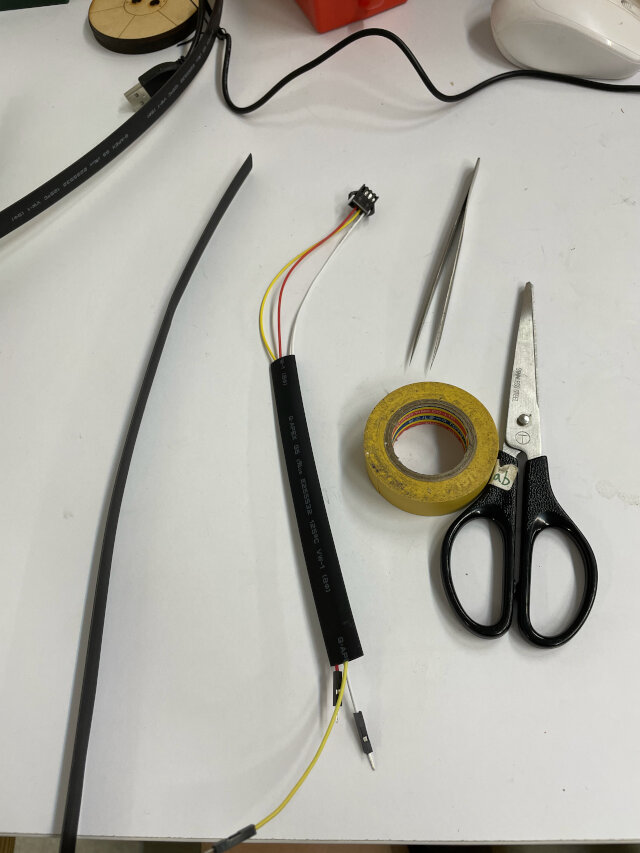
Then I came to deal with wires again, with only one PCB I need 7 wires between map and scoreboard (3 for neopixel strip, 4 for LCD). For neopixel strip, I solder an end of neopixels with male 3 pin terminals, and do the same with female one with dupont wires connects to PCB. For LCD, I just tape 4pins dupont wires together and using the corresponding color. Plan to buy some plastic cover to put on them.
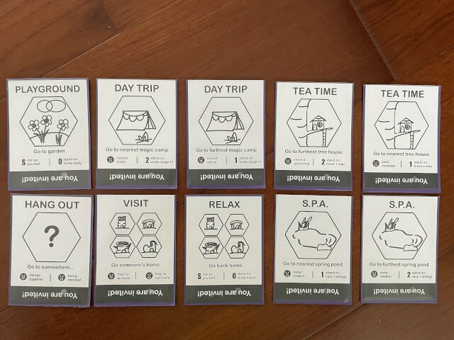
My final job is designing cards. Refer to my work previously, I design rules and write description on it. Even add some icons and do color matching. But when it comes to mass printing, I got to arrange many cards in one page and send them to printing shop. Need to consider cutting mistake (left some area to paper edge) and line for cutting reference. Since I was injuried so I paid for them to cut for me (but cutting took even more than paper plus printing).
Note: be aware of card size and card sleeves size. I used 63.5mm88mm this time but this is for card sleeves. This is even a larger one and the regular card size is 55.9mm87.1mm.
Reflection questions
- Tasks completed?
- Laser cut Turntable and colored
- Decoration LEDs with matt acrylic
- Integarte codes into all-in-one
- Package wires with plastic cover and terminals
- Card design and printing
- Video and slide (see final project)
- Tasks remain?
- Testing and debugging (LCD)
- More decorations and improve packaging
- Separate game map and scoreboard (2 PCB, 2 power supply, and wireless communication)
- Redesign box space layout for disassemble
- What’s working?
- Needle on turntable can rotate smoothly
- What not working and need to be resolved?
- Resin is expired and become fixed itself (buy another one)
- What have I learned?
- Use spray to turn transparent acrylic into matt (cost less)
- Consider how to disassemble and arrange things first (if it can be portable)
- Use terminals or just solder to make wire connection more stable
Spiral2 results
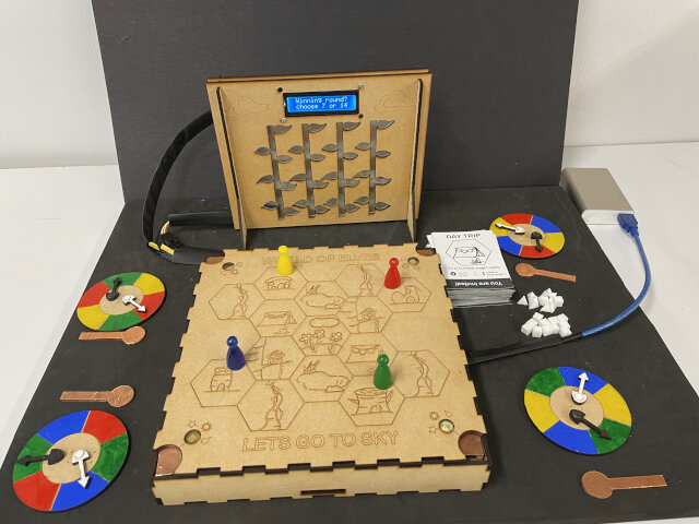
Lest note: Thinking how to arrange PCB and wires and provide power really takes me lots of time, and the result is still not very good. Next time should consider packaging first, and also how to setup & disassemble everything。