6. Electronics design
Group assignment
- use the test equipment in your lab to observe the operation of a microcontroller circuit board
Documentation at: Fablab Taipei
Individual assignment
- redraw an echo hello-world board, add (at least) a button and LED (with current-limiting resistor) check the design rules, make it, and test that it can communicate
- extra credit: simulate its operation
This week I worked on customizing my own PCB design base on “Hello World Board” and try to mill and solder it.
PCB schemtic design with EasyEDA
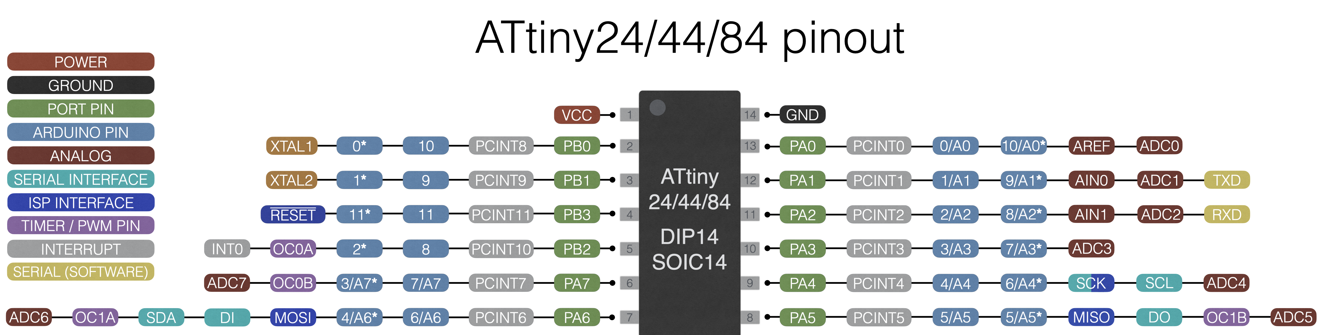
Design with ATtiny44 microcontroller, pinout as image shows (refer to ATtinyCore)
First I refer to the original hello world board design, together with Yoyo’s design, and have all components I need on the board with EasyEDA.
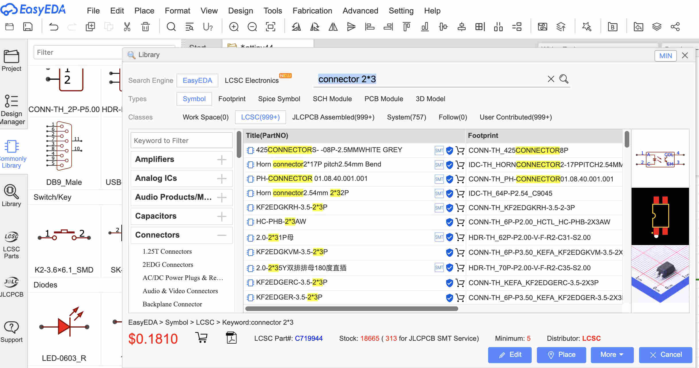 Hint: for searching something complex like connectors, you may need to search specific keywords.
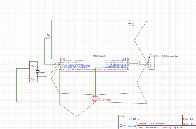 This is the original hello world board design before any modify. (I also spent some time looking for proper component to put on)
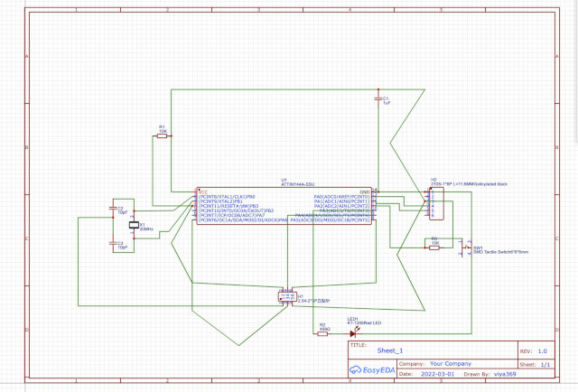 Add on LED and button.
 Start puzzling!
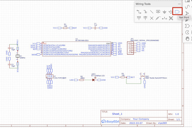 Suggested by someone, with net port it become easier and looks better!
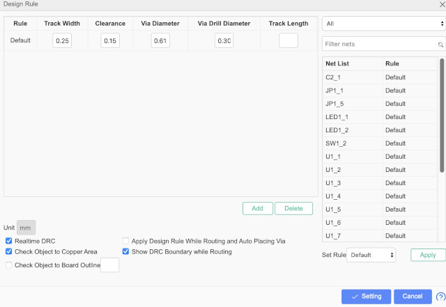
Attention: try to check this before routing!
Then try auto-routing first, but it showed up not very well (net crossing between MCU pins, which is very small and always get to close between nets).
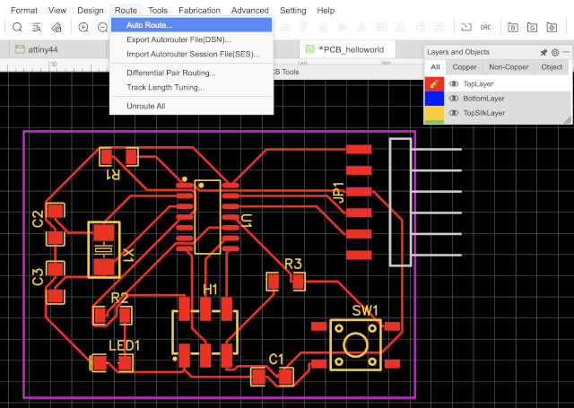 This is auto routing results.
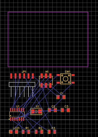
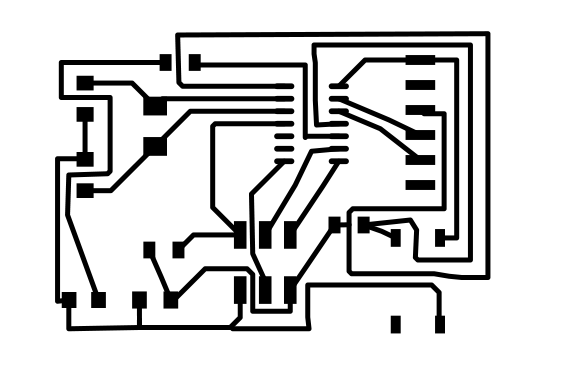
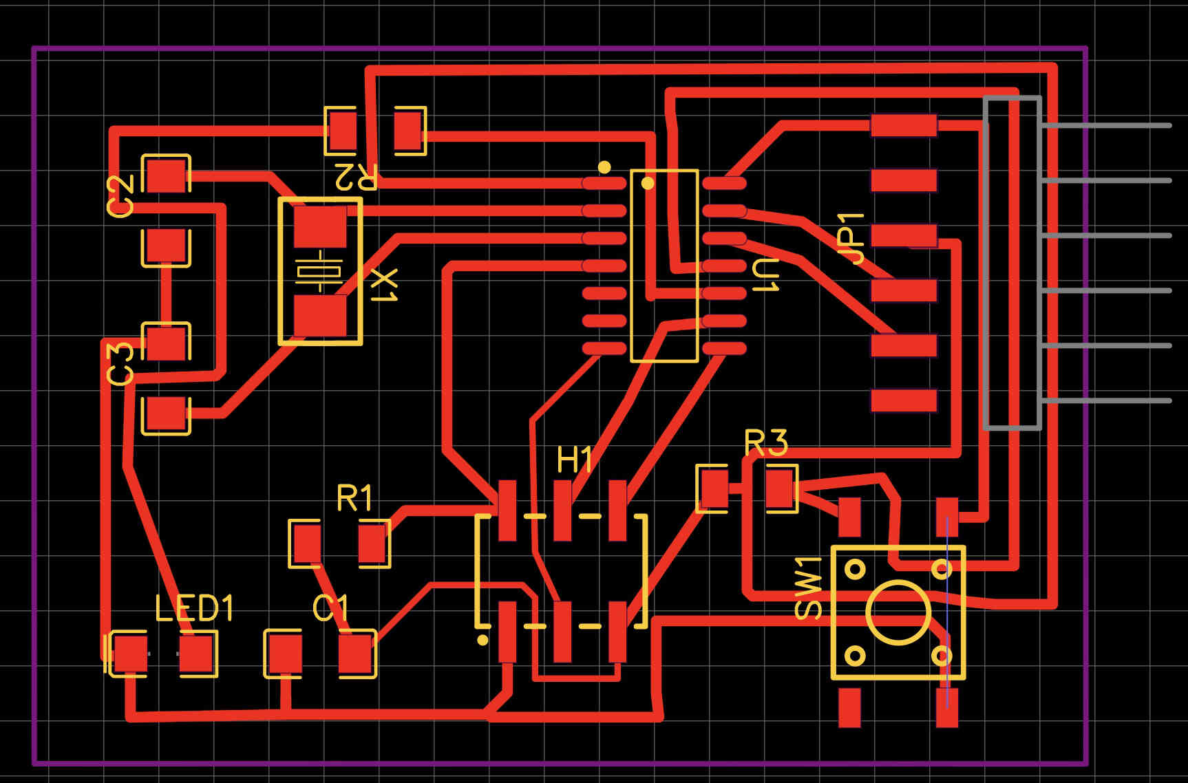
 This is the one after my adjustion.
So I spent about 2 hours to figure out my own routing solutions. Which is a puzzle but feels good while it success!
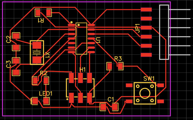
My final works: traces and outline
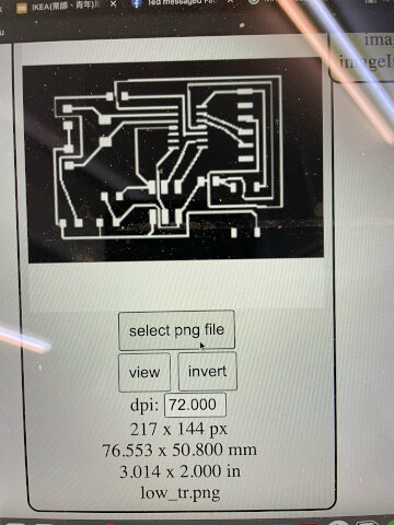
Export problems

EasyEDA doesn’t export PNG file well. The resolution is terrible (cannot adjust).
Later my inteructor Ted gave a solution: export PDF first and transfer to PNG file. But a problem again, the image comes bigger and need to figure out what’s the proper percentage to resize. And that’s harder than I thought in many ways…
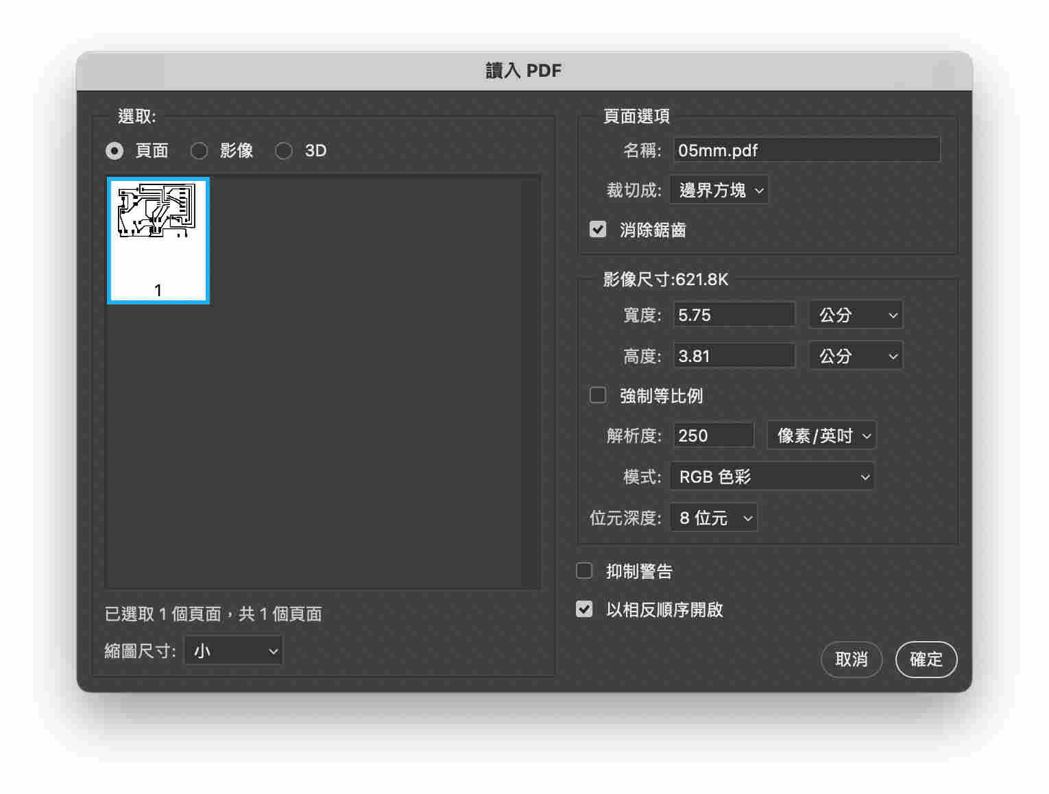 解析度 dpi 250 works fine for me!
P.s. always remember to “invert” the BLACK & WHITE color of the traces image. We both did it wrong once… (you will cut out what you want to keep)
Not sure about the size until it cut out… in mods you need to find “333 x 333 mm” or “333 x 333 in” for example as real size, not the px.
Update: try design with Kicad
I design more PCBs with Kicad because there’s a library for common components we used in Fab academy!
Documentation at: week10
But EasyEDA still have adventages such as autorouting, and we can easily send design to board house to manufacturing!
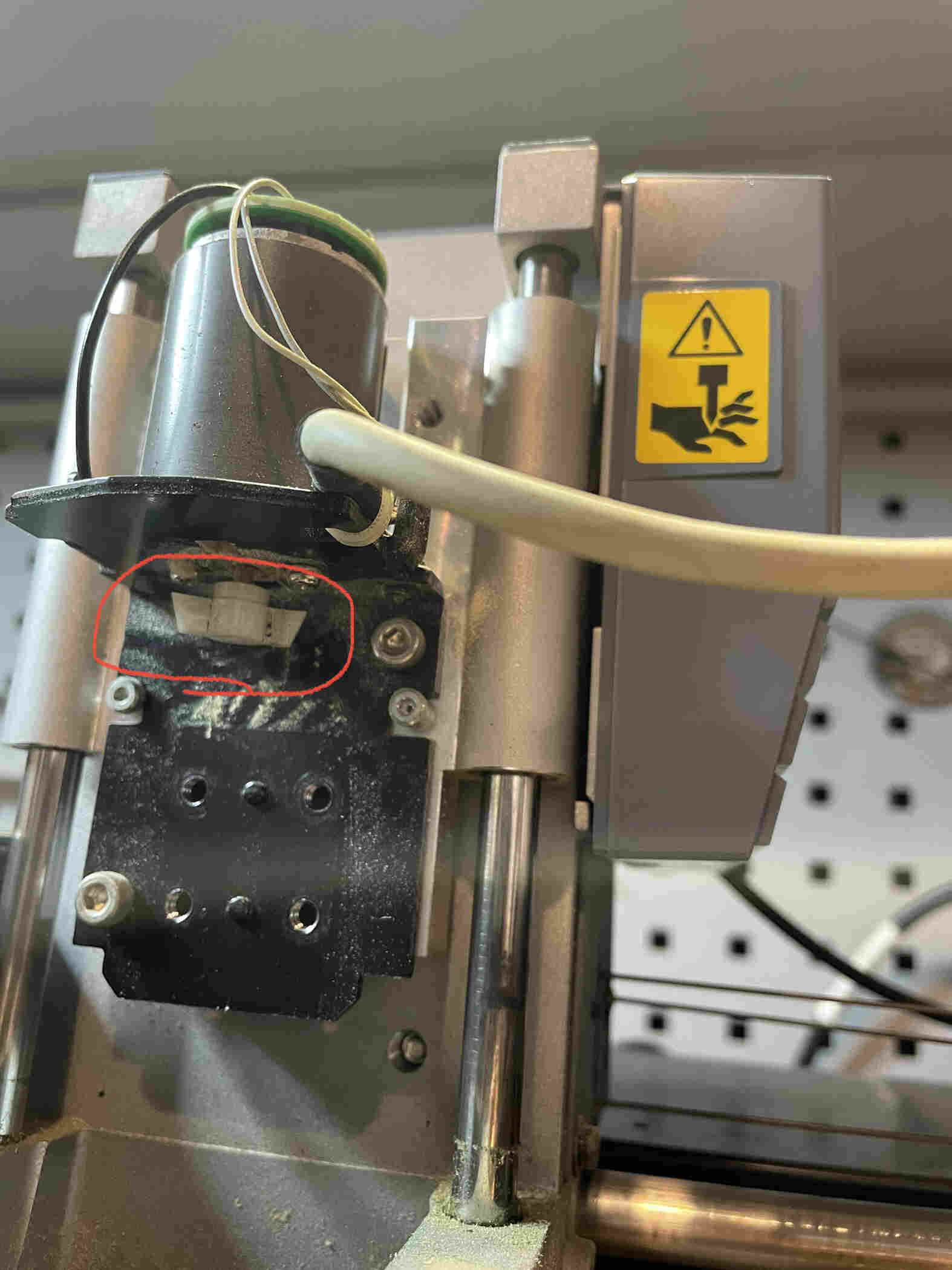
Milling: Try in different ways
When milling the board with MDX-20, it failed many times due to FR1 moving. That’s frustrating and I thought the problem is the sacrificed board (wood). But later on when milling wood the motor got slower… Seems like doesn’t work. Yoyo even unvover the motor and found out the possible problem (loosing part.)
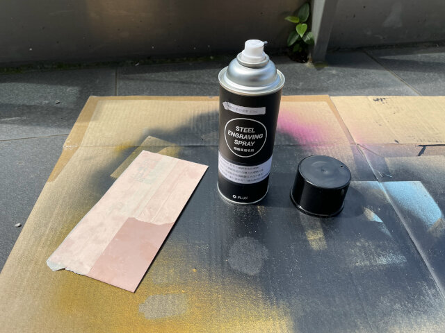
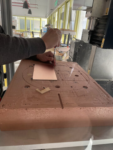
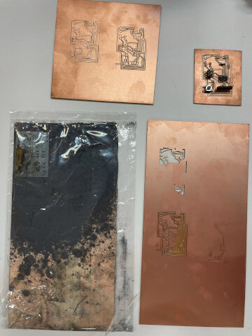
Tuesday I spent the whole day trying to cut the board with other machine, even go to my school.
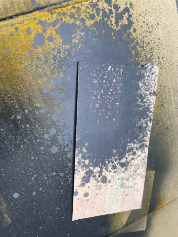
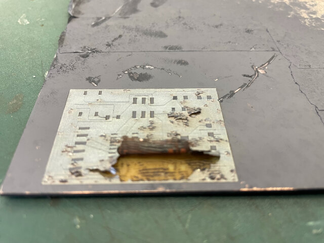
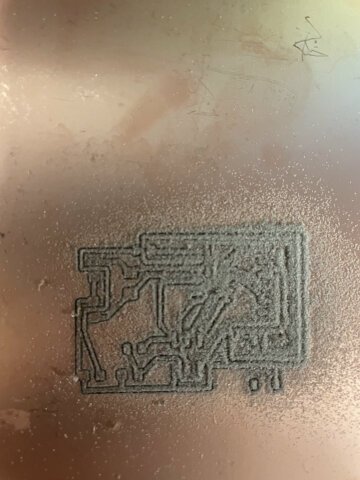
I tried laser cutting the board with a special sprayer (absort laser energy and melt metal). But it turns out that copper cannot be cleared completely and failed.
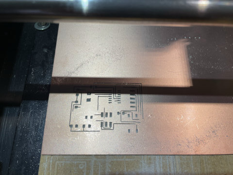
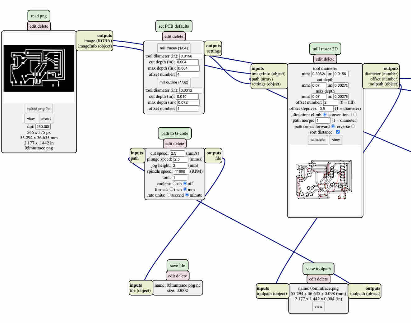
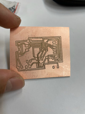
Using mods to generate path, this one works! (only modify parameter in mill raster 2D)
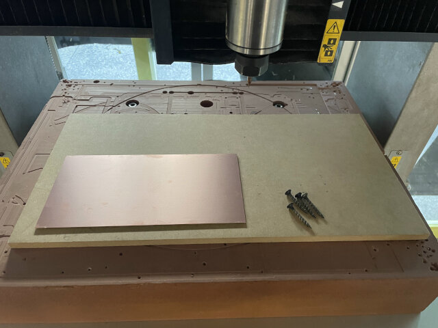
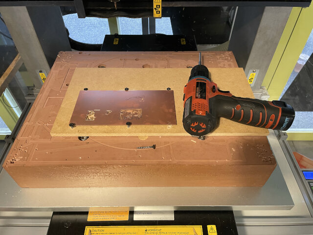
And then I tried on the bigger CNC (MDX-540), but how it works is a lot different from MDX-20, from hardware to software. Need to test and improve many times. Even the hight of its sacrificed board is not enough, we tried many ways to solve it. Finally with another wood on it and screw to fix wood and FR1 with sacrificed board together!
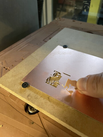
Fail many times, even ned to make the wire thiner to work out or it will disappear…
- Default wire width: 0.5mm
- Changed wire width: 0.3mm (to go through between connector pins)
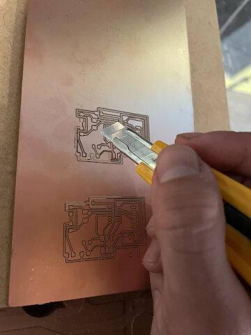
I even tried to use utility knife to fix it.
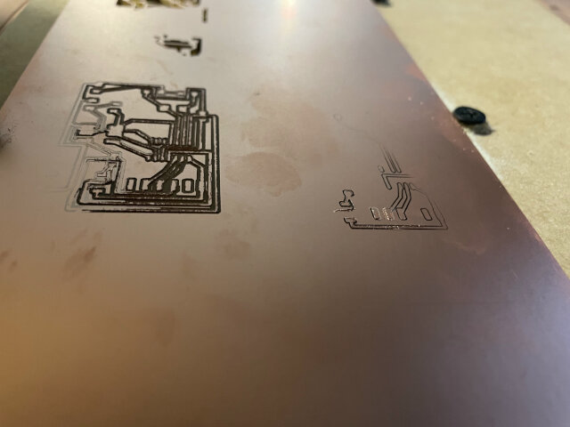
Finally works until 2 days trial and error.
For someone who is crazy like me
If you want to try MDX-540 for PCB milling, better know these stuff.
- We use 0.3mm endmill. If you know your endmill size, check your PCB net width and clearance first. And don’t need to adjust your design on halfway.
- Try to make the surface be as horizon as possible. If you use some screws to fix the FR1, that might not be a good idea… There will be a curve and destroy half of your board.
- Fail fast and have another try. set offset number to 1 or 2, if you find the trace too light or deep, change the cut depth ASAP.
It should not be that hard actually… for me I spent a lot of time to with unhorizon surface and try to make it works… just test it fast and be aware 3 things I mentioned above. Good luck!
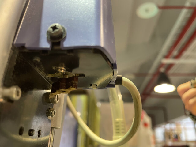
Plus: Fixing the head of CNC
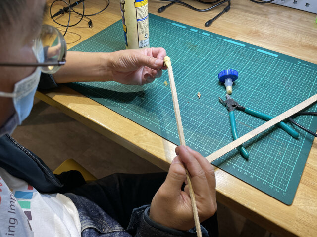
While I trying to cut in different ways, Ted asked his friend about how to fix the machine, and came up with the idea: cut a new one to replace the old one!
The idea is to test press fit and laser cut two same shapes and stick them together and replace the old loosing one. it works!
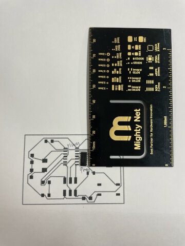
Got my first PCB! and…
The final design version
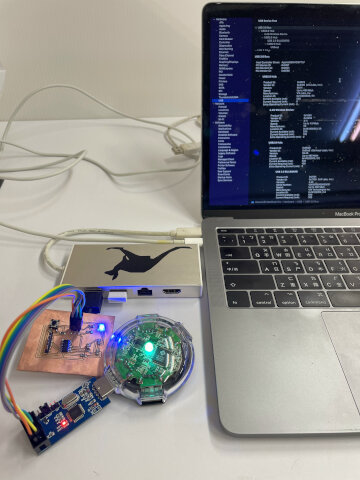
After many trials, I got my PCB finally and solder everything.
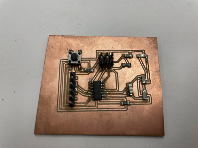
But later on I tried to connect it to computer and burn the boot loader, happy to see the LED light on! But then when connecting to Arduino Uno it burned!!!! Debugging
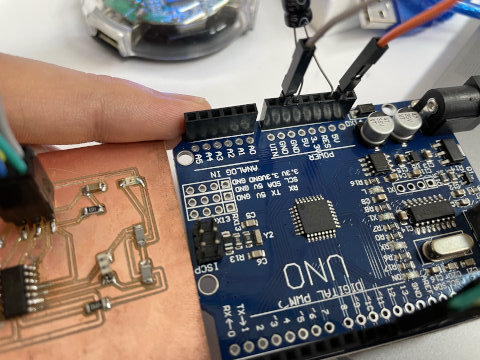
Somehow the problem fixed itself later (See week08), but anyway still be aware of these 3 things. - LED anode and cathode are in right direction. - Resistor value is proper (too small it will burn, too big it won’t light up) - Wires don’t contact accidentally (so avoid to let a trace go under a tiny/SMD parts with footprints very close)
Update: using THT part on SMD board is not a good idea…
Since we have 20MHz THT crystal only, we use it on our board which should use SMD package. The result is that I got to fix the leg with solder several times because it was broken.
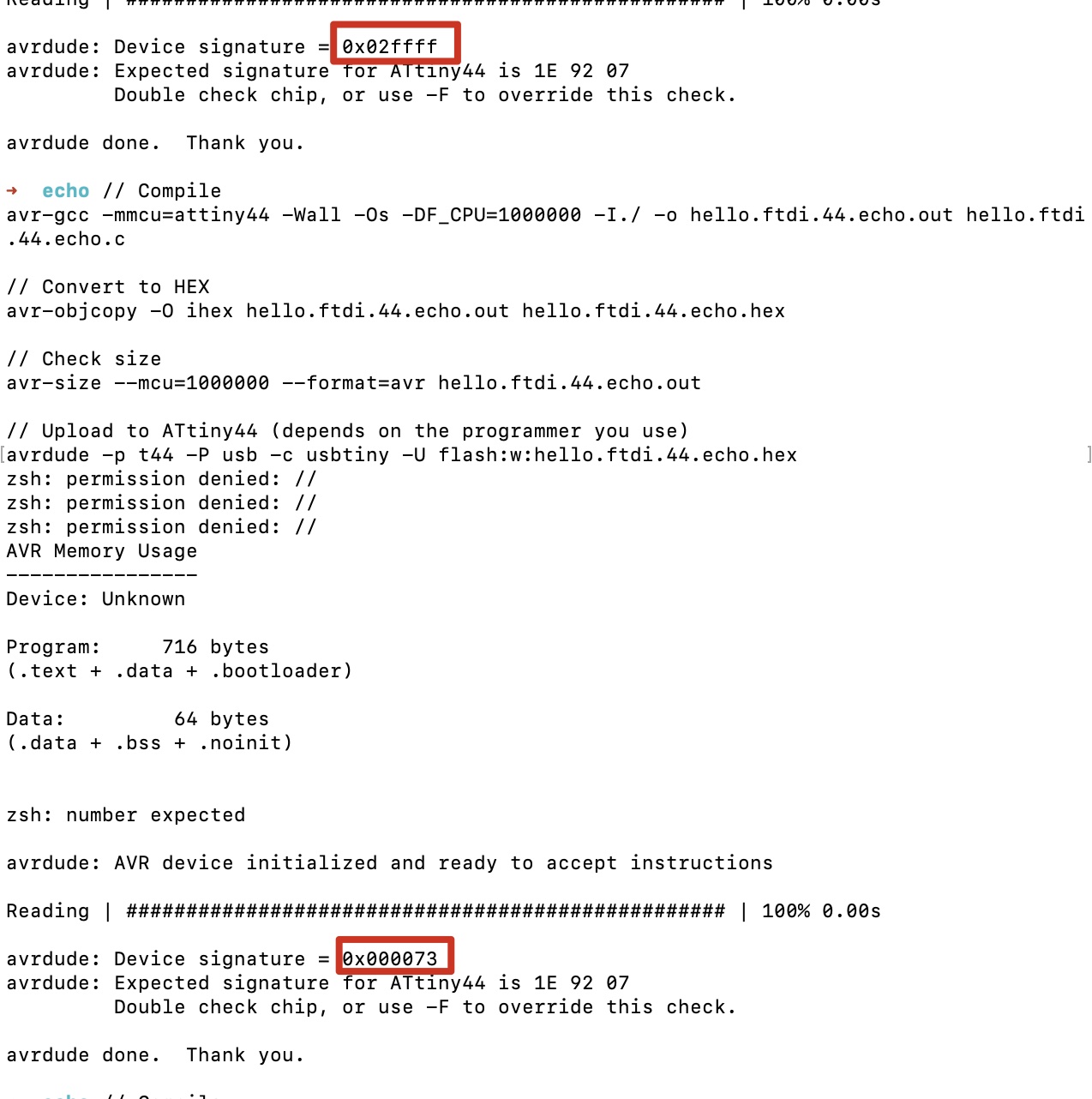
And not to mention that I spent lots of time debugging (keep encountering wrong signature warnings when programming) and thought the chip is broken but found out it’s the unplug crystal…
Design files
Useful links
I knew this week that we can click on the title of each week’s sites and go into fab inventory, which includes material that we may use (and Fablab should be able to provide if needed).