14. Networking and communications
Group assignment
- send a message between two projects
Documentation at: Fablab Taipei
Individual assignment
- design, build, and connect wired or wireless node(s) with network or bus addresses
This week I aimed to try both wired, wirless and socket networking method. Wired: serial bus (Attiny45), Wireless: remote switch (Esp32), and Socket: terminal communication (Python).
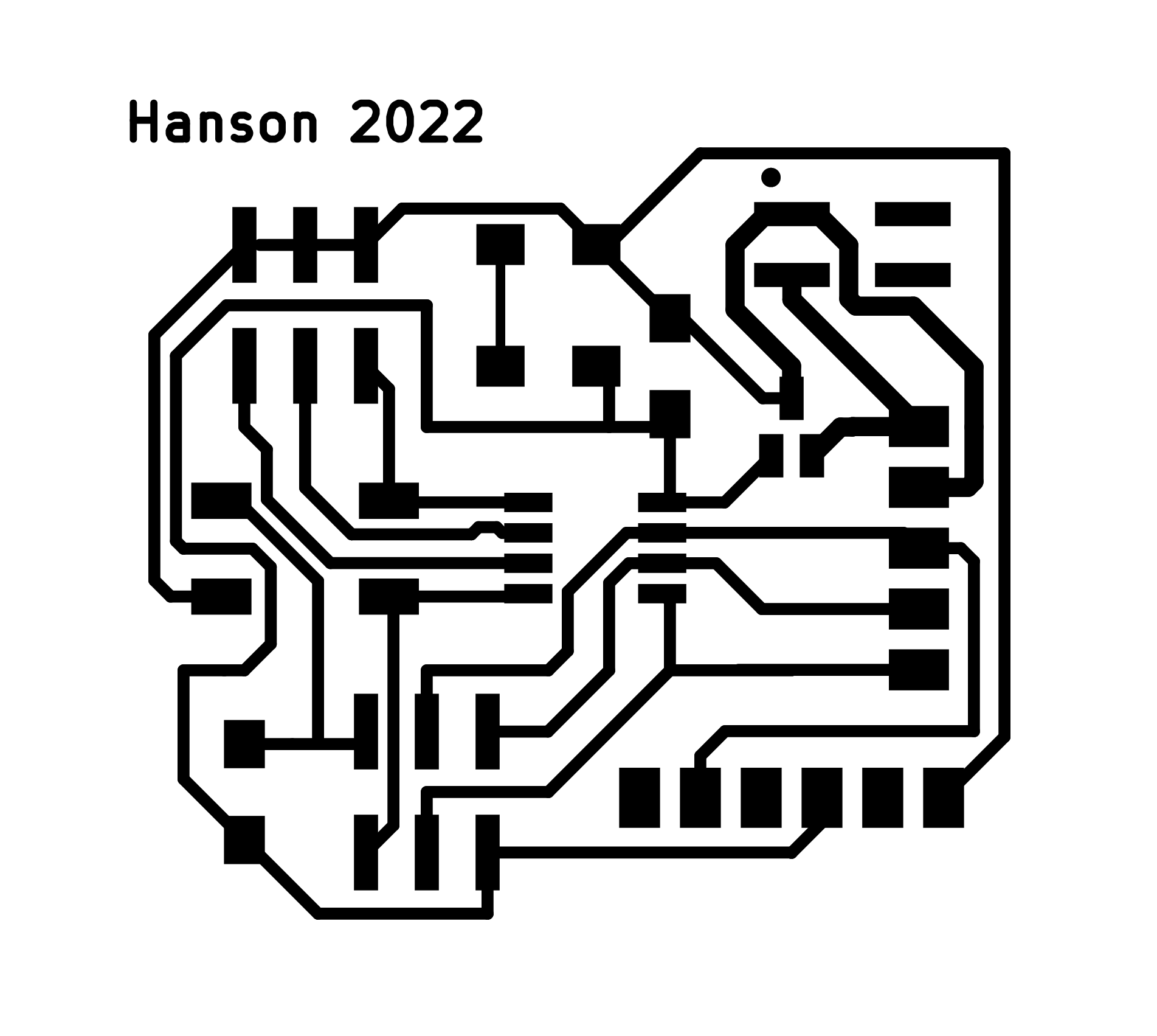
Pre-tasks: Board improvment
Continued from input/ouput weeks, I kept improving my attiny45 core module.
ATTiny45 pinout
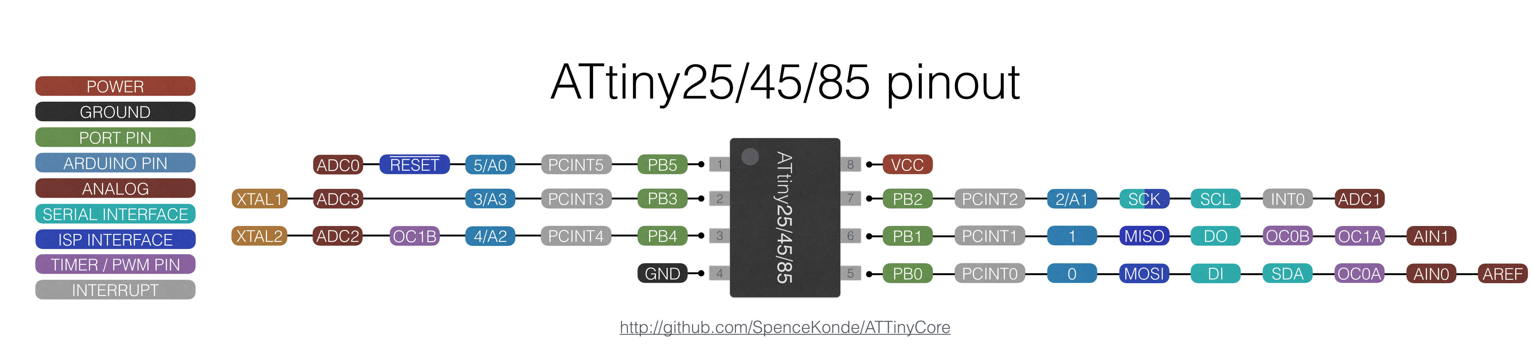 And also found this repo very useful. ATTinyCore
Attiny45 clock: internal 8 MHz
Version1
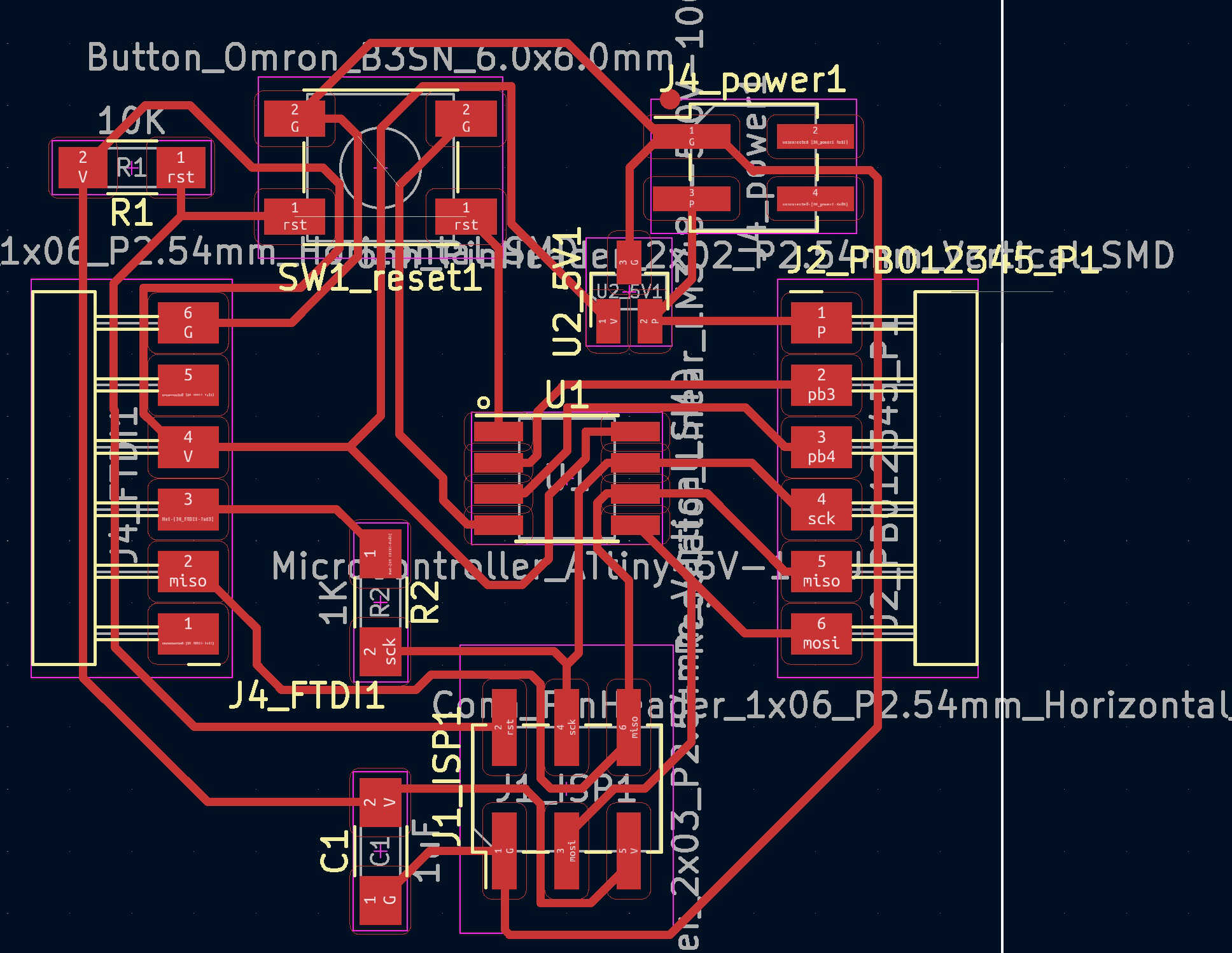
Version2 (divide output pins / add power LED)
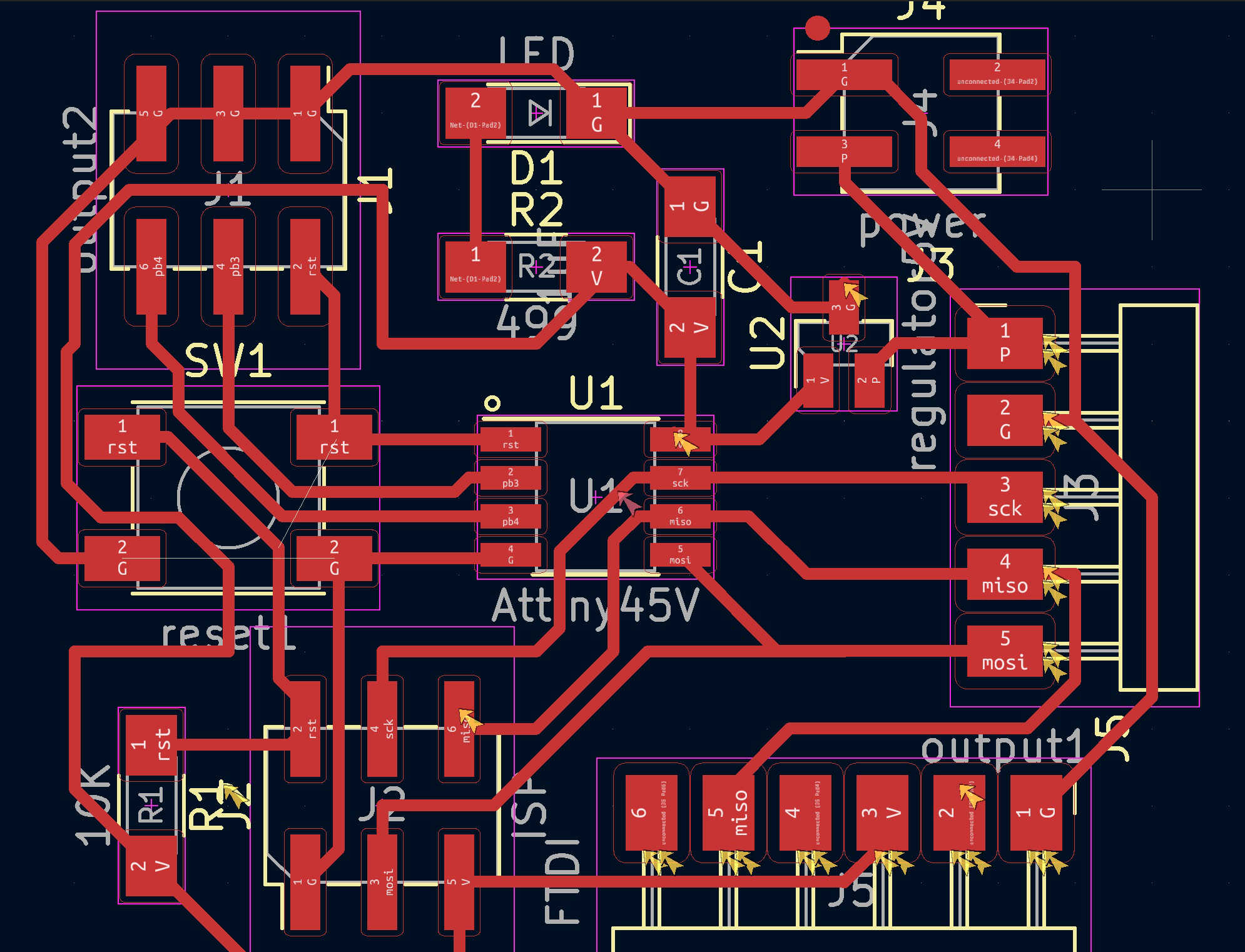
Version3 (fix rx pin to sck / add name)
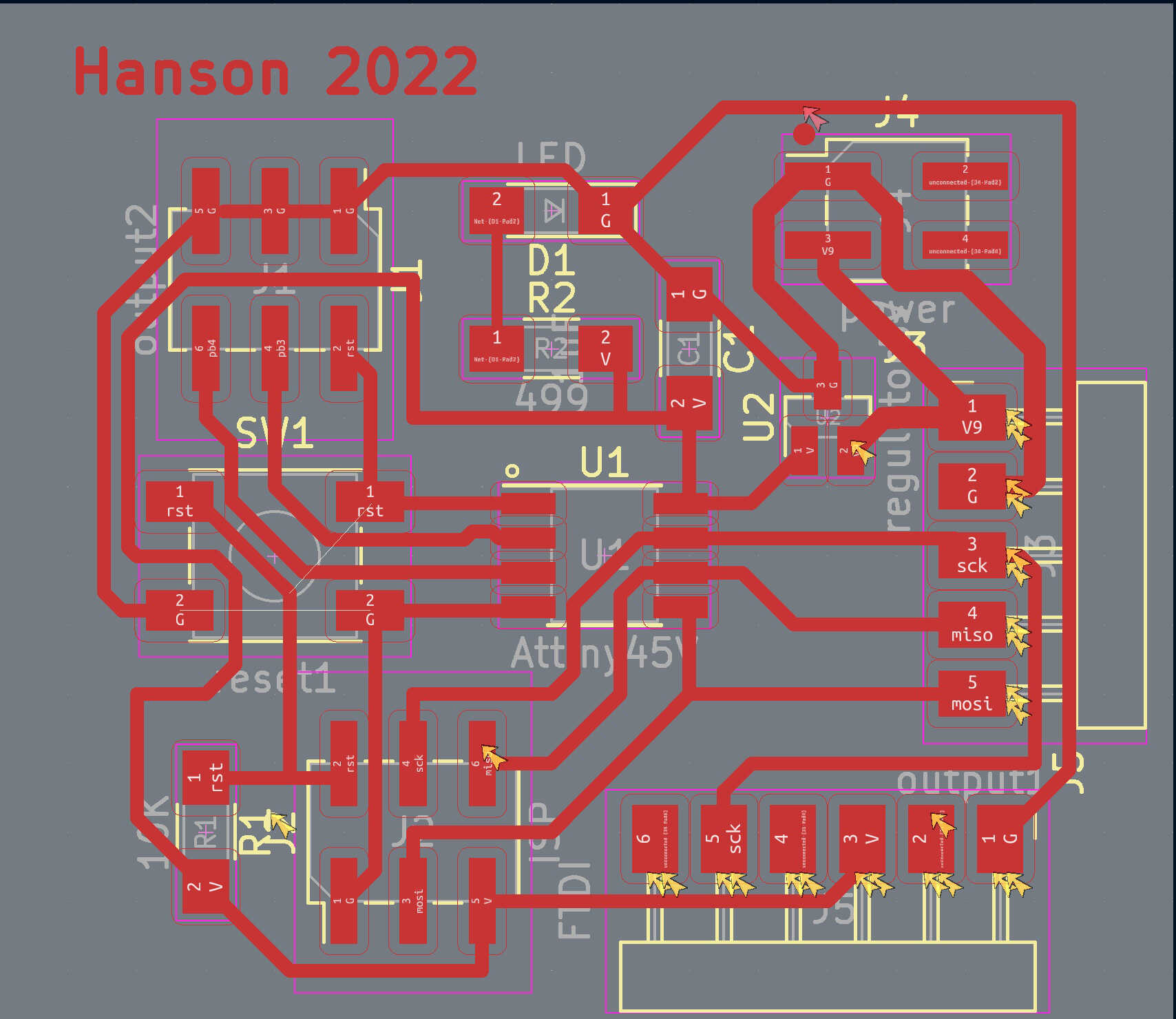
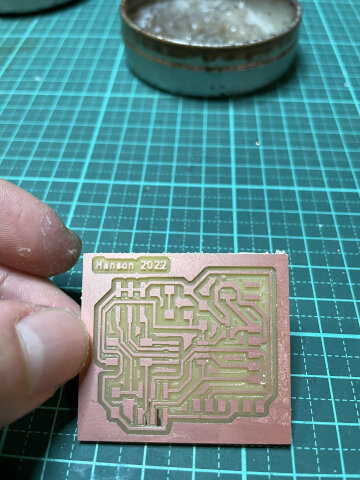
Update: regulator debug
I had 5V regulator on the PCB design but the one I bought before isn’t compatible (while I tested, with the regulator on it microcontroller doesn’t work or even have smoke out with about 10V!)
Finally I found its datasheet (it’s cheap one found on shopping website and digits on it has no meaning, even seller doesn’s know ehat is it), and surprisingly understood that evev its package type is also SOT-23(3), the pinout is completely different from the regulator in Kicad fab library.
I redesign the board to fit in and it’s fine now~ Some testing pic:
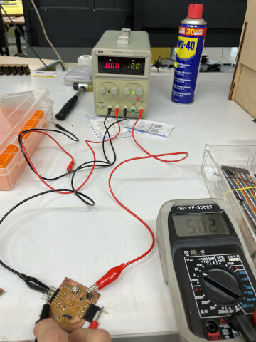
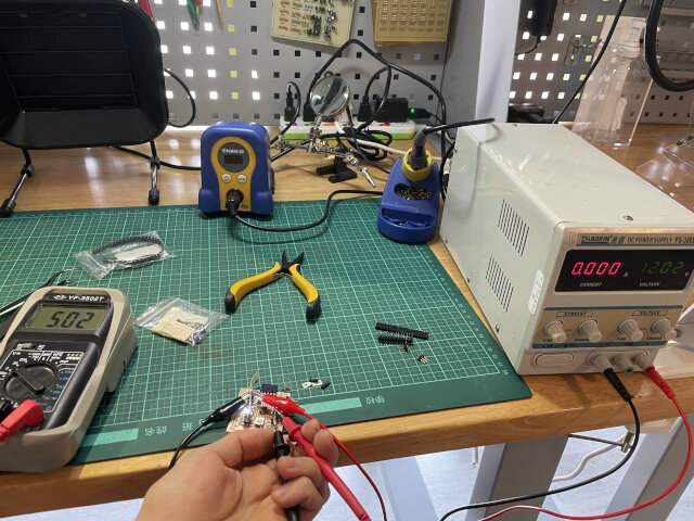
Wired: Serial bus (Attiny45)
And I got 3 attiny45 boards to try Neil’s attiny45 serial bus exampl in networking week! At first I tested LEDs on project board to make sure they work.
Also make a bit study on how to use project board.
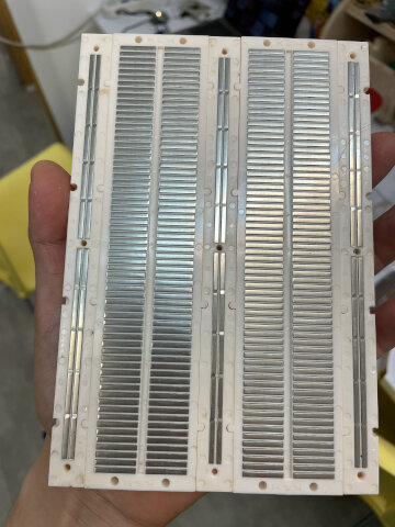
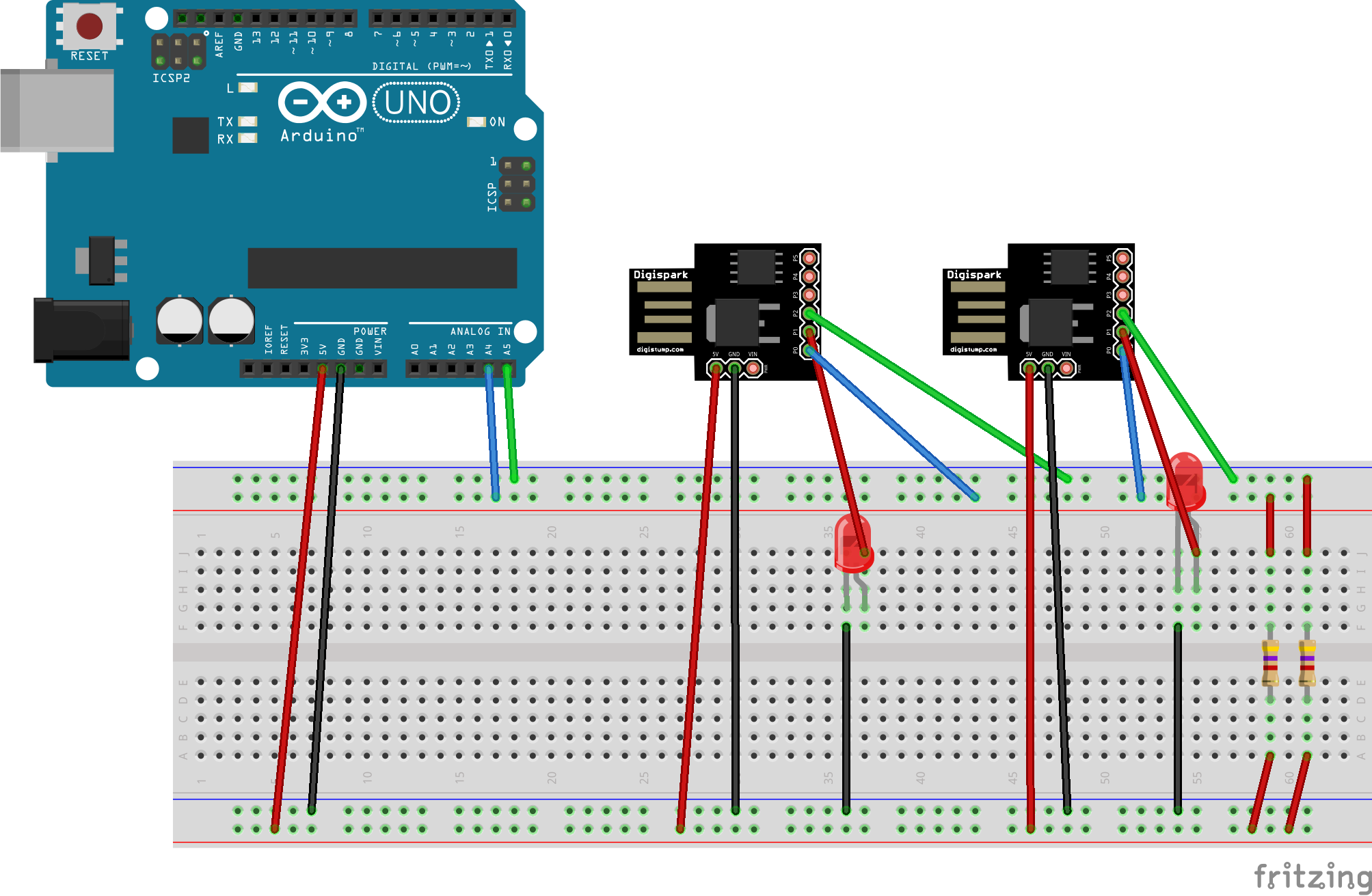
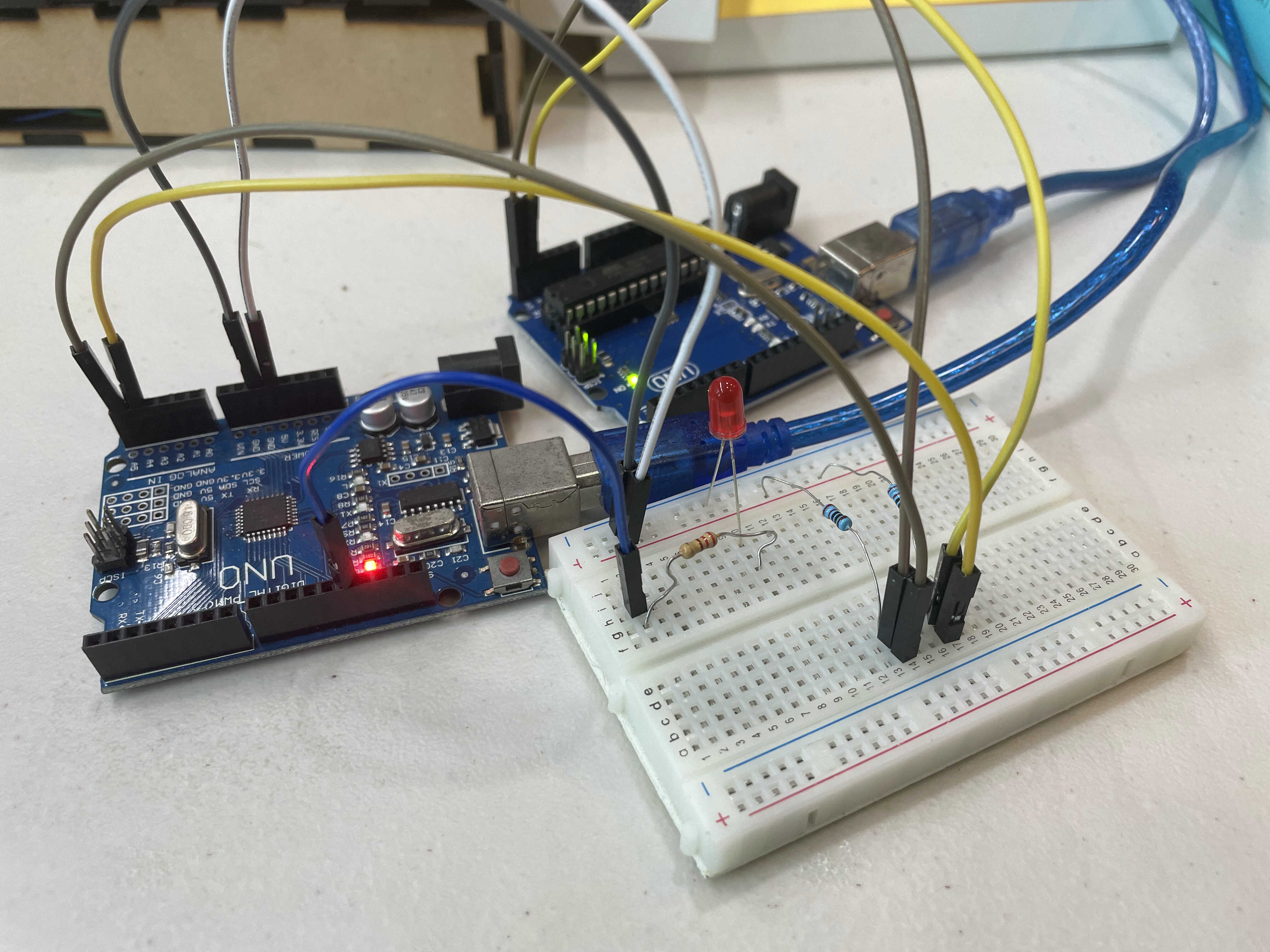
Finally, this is my setup to connect 3 boards and test serial bus.
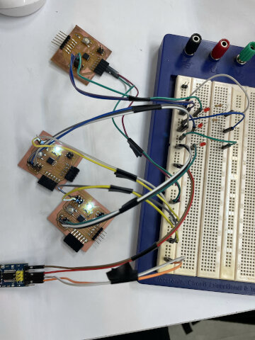
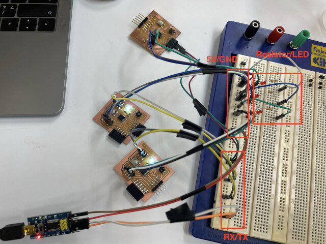
Read through tutorial, I understood the code needed to be modify for three boards: #define node_id '0', #define node_id '1', #define node_id '1'. And also found out just need to type “0”, “1”, “2” in serial monitor and LED response!
Update: Bi-direction communication
Furthermore, I tried Neil’s hello.bus.45.SLIP example using the same 3 boards. Again this code need to be modified for each board. Refer to his video demo and this site
#define ADDRESS_0 10
#define ADDRESS_1 0
#define ADDRESS_2 0
#define ADDRESS_3 2 // change this line
#define ADDRESS_3 2, #define ADDRESS_3 3, #define ADDRESS_3 4 should be used for each board.
Together the python code has some bugs.
- Add
import sysin the beginning - Line 33: change
raise IOError, "timeout"toraise IOError("timeout")reference - Line 80: change
ser.write(chr(byte))toser.write(chr(byte).encode())refer to this thread and thiswebsite(in Chinese)
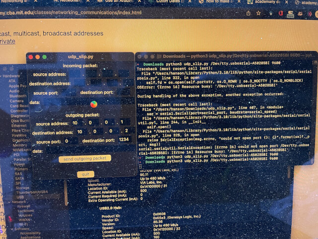
And then you can type “python udp_slip.py serial_port serial_speed” in terminal (cd to the folder where your python code is first). In my case I type
python3 udp_slip.py /Dev/tty.usbserial-A50285BI 9600
And open the python window successfully. But somehow my cursor change to loading symbol and python appliction not responding every time after opening window. Still don’t know why.
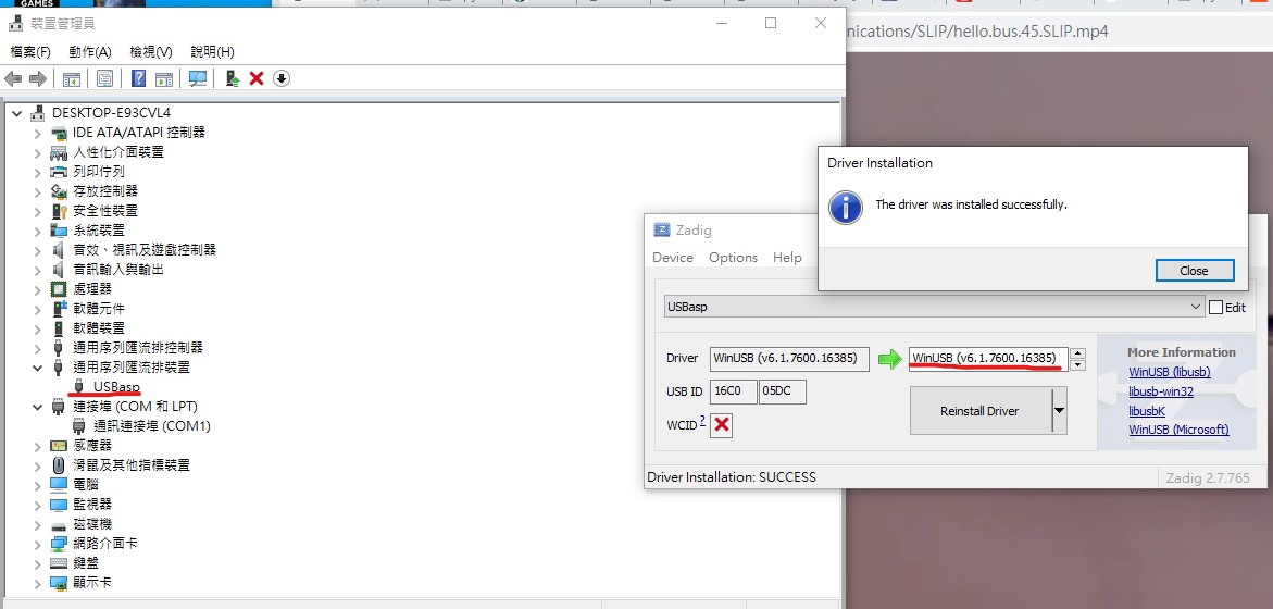
Later I tried on Windows computer. First problem is “USBasp” programmer require driver on Windows. This video shows a quick tour to install driver “Zadig”. Download it here. And when install successfully, you should see it in USB list.
Well it turns out the program still doesn’t work, even using destination port “1235”, incoming packet doesn’t response as in Neil’s video. I think there’s something wrong in the code itself. (Note: when trying on Mac, Python stop responding once I run the program; on Windows it just doesn’t response to my action, and after a few seconds the program stop responding as well.)
I tried serial bus again to make sure wiring is right. Although sometimes there’re some nonsense charactor in serial monitor, LED still flash correctly. And in SLIP communication test, even I test with the only board doesn’t has nonsense charactor, still no response.
Update: I2C bus
After searching for some I2C practices done by previous students, I refered to student1 master & slave code, and also student2 I2C scanner.
First I programmed 3 attiny45 boards using USBasp, and also try to see if they works. Sadly only master response to me, while slaves did’t answer. Next I tried I2C scanner using Arduino Uno, and see if if able to detect those slaves I2C address. And that works! (I also learned to put 2 1k ohm resistors between SCL/SDA & 5V)
next I came back to test master & slave code again (with 1K pullup resistors), unfortunately it turned out to be the same. I thought there might be something wrong with my board, and maybe test commercial board next.
I later tested all 3 boards to be master one by one, there’s no difference in the consequeces.
Note: something also weird is that in serial monitor, nonsense characters happened again and even non-expected serial print wors “you type: ” (without data). And it may root in a data tranmission problem and also leads to error in I2C network.
Update: I know SCL and SDA line should be 5V when no commands comming. When I use petentiometer to test them, SDA/GND is 5V but SCL/GND is 0.5V. No matter I use 220ohm, 1K or 10K resistor. Maybe that’s the reason why I2C doesn’t work.
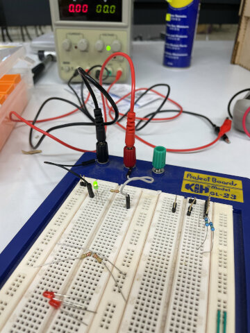
Lastly I decided to try I2C using my Arduino Uno boards, since I only got 2 of them, they may not be a “bus” but I managed to simulate the bi-direction communication of LED status.
After searching for many materials online and learn basic I2C principle in video above (thwy also have an article), I first try this example from Arduino | I2C pactice(in Chinese), and then using this example from My Arduino Note(In Chinese) to make some modify and become my code.
I connected 2 boards A4(SDA) and A5(SCL) pin and using 2 220ohm resistors to “pull them up” to 5V. and then simply connect 1 LED & 220 ohm resistor to slave board.
It works well! Then maybe using commercial boards are more reliable and easier sometimes
Wireless: Remote switch (Esp32)
I want to build a remote switch at home, and able to turn on light when the button is pressed. (So once mosquitos come at night, just turn the light on and kill them!)
I used my claw design at week 11 and sample code Servo > Sweep in Arduino IDE to make a test.
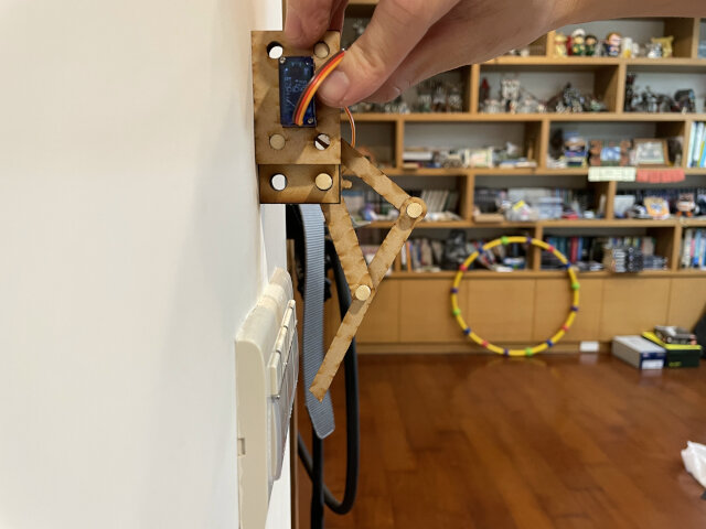
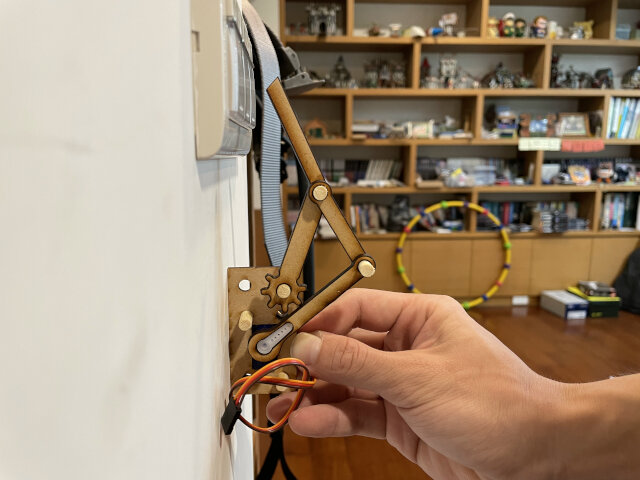
But unfortunately, the servo motor is not strong enough to push the button, may need a stronger one.
ESP32 setup
When I tried ESP32 in lab it’s fine, but after going back home, I used a USB cable to connect ESP32 and my Mac cannot detect it!
I found this thread has solution which is downloading driver for USB to UART but even with driver it still not shows up. And then I changed to another USB cable and it just works!
Another full guide to Installing the ESP32 Board in Arduino IDE (Windows, Mac OS X, Linux).
Note that ESP32 is not compatible with 5G wiFi reference. And use “EN” button to reset (“BOOT” button refers to bootloader mode) reference.
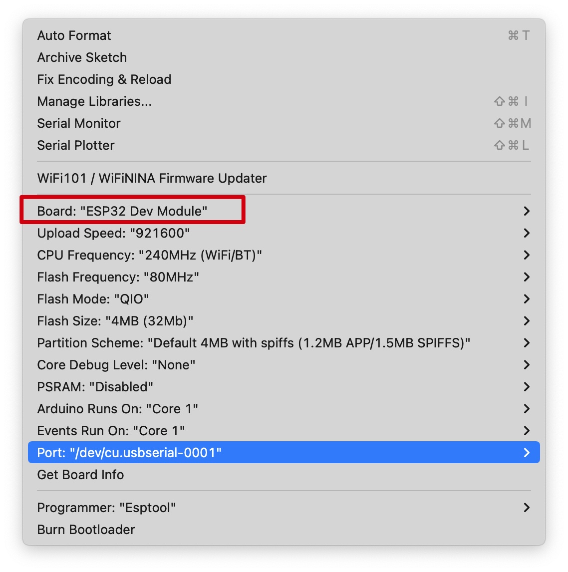
so many options of ESP32 boards to choose, simply choose Dev module is fine.
Control servo on webpage (WiFi)
Then I tried another code refering Control Servo with ESP32 over WiFi (Robojax), and code to control servo through webpage. I successfully connect it to wifi at home and when pressing button on webpage, it works!
Notes:
- Need to have Arduino ESP32 support and ESPservo library.
- If you also get a ESP32 version that without “5V” pin, can just power servo with external 5V and receive signal from ESP32.
- If you get an error message when programming
exec: "python": executable file not found in $PATH
Error compiling for board DOIT ESP32 DEVKIT V1.
, run this can solve it reference
sed -i -e 's/=python /=python3 /g' ~/Library/Arduino15/packages/esp32/hardware/esp32/*/platform.txt
In this video, when pressing the button with number, the servo motor should turn to that specific angle (number on the button). But instead the servo kept spinning and the number seems to determine its speed.
Adapt code with “Continuous servo motor”
I did some research and found this thread explained continuous servo motor has different attributes when using myservo.write()
* 0 means max speed clockwise
* 90 means no motion
* 180 means max speed counter-clockwise
I then tried to modify code to fit in contituous motor but failed (all code structure of the author is based on one int call “Servoangle”). Then luckily in Asia review instructor Yuichitamiya share switch-bot with me.
After trying this, I still encounter the same problem. Later I found out that PWM duty cycle in the code is using ledc function reference.
for(int i = 0; i <= 180; i++){
  ledcWrite(0, i);
  Serial.println(i);
  delay(250);
}
My test result is having “75” servo will not move, while having “30”, “120” are the maximan speeds for clockwise or anti clockwise spinning.
Well even figure out the right PWM for servo motor, I still need another stronger motor to make things work. TBC.
Note: I did check the datasheet for Servo Motor SG-90 but it doesn’t match for the one I have…
Remote switch testing in my room
Finally I bought another servo motor “MG90S”(datasheet) and this one isn’t continuous servo, so it’s easier to control!
Refer to ESP32 Web Server – Arduino IDE for its webserver setting and Fablab Kannai for its motor controlling (Note: Fablab Kannai’s code you have to edit IP address in code every time, but another doesn’t need), I wrote my own code for a simple remote swich.
First I tried to use Servo.h library and found out it doesn’s ssupport ESP32. So kept using ledcWrite. And then I spent quite a time understanding how to setup webserver, such as using indexOf() to detect changes in url and trigger corresponding action.
Lots of code used are actually fixed template, and understanding basic syntax can let you modify easily. I also found some thread discussing how to shorten HTML5 Doctype thread and blog(in Chinese).
/*********
  Fixed template for webserver
*********/

#include <WiFi.h>

// Replace with your network information
const char* ssid = "YOUR WIFI SSID";
const char* password = "YOUR WIFI PASSWORD";

// Set web server, servor
WiFiServer server(80);

// Variable to store the HTTP request
String header;

void setup() {
  Serial.begin(115200);

  // Connect to Wi-Fi network with SSID and password
  Serial.print("Connecting to ");
  Serial.println(ssid);
  WiFi.begin(ssid, password);
  while (WiFi.status() != WL_CONNECTED) {
    delay(500);
    Serial.print(".");
  }
  // Print local IP address and start web server
  Serial.println("");
  Serial.println("WiFi connected.");
  Serial.println("IP address: ");
  Serial.println(WiFi.localIP());
  server.begin();
}

void loop() {
  WiFiClient client = server.available();   // Listen for incoming clients

  if (client) {                             // If a new client connects,
    Serial.println("New Client.");          // print a message out in the serial port
    String currentLine = "";                // make a String to hold incoming data from the client
    while (client.connected()) {            // loop while the client's connected
      if (client.available()) {             // if there's bytes to read from the client,
        char c = client.read();             // read a byte, then
        Serial.write(c);                    // print it out the serial monitor
        header += c;
        if (c == '\n') {                    // if the byte is a newline character
          // if the current line is blank, you got two newline characters in a row.
          // that's the end of the client HTTP request, so send a response:
          if (currentLine.length() == 0) {
            // HTTP headers always start with a response code (e.g. HTTP/1.1 200 OK)
            // and a content-type so the client knows what's coming, then a blank line:
            client.println("HTTP/1.1 200 OK");
            client.println("Content-type:text/html");
            client.println("Connection: close");
            client.println();

            // Display the HTML web page
            // CSS to style the on/off buttons
            // Web Page Heading

            // The HTTP response ends with another blank line
            client.println();
            // Break out of the while loop
            break;
          } else { // if you got a newline, then clear currentLine
            currentLine = "";
          }
        } else if (c != '\r') {  // if you got anything else but a carriage return character,
          currentLine += c;      // add it to the end of the currentLine
        }
      }
    }
    // Clear the header variable
    header = "";
    // Close the connection
    client.stop();
    Serial.println("Client disconnected.");
    Serial.println("");
  }
}
Wiring setting: ESP32 pin14 > servo PWM; FTDI conveter VCC/GND > servo VCC/GND. (because ESP32 is 3.3V, and servo motor require 5V)
I can use it to turn off light in my room (although try many times… one is because WiFi lag, another I think this switch is designed for human to control lol). Full code can be download at the bottom of page.
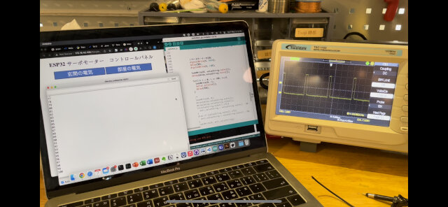
Oscilloscope testing
To find out why these 2 codes performs different while turning angle (first on 90degree will stop, while second on 75degree will stop), I used oscilloscope to find out what’s going on.
Recommend this video to learn how to set up oscilloscope: How to Use an Oscilloscope
First I test Robojax’s code and record its PWM wave at 180degree.
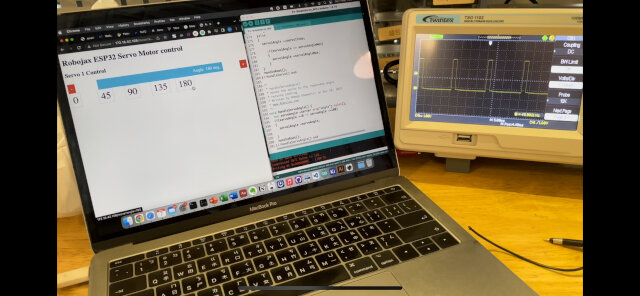 ANd surprising found the wave pattern is similar to 100degree in Fablab Kannai’s code.
Later I got the point that in Robojax’s code, there’s a int servo1Angle_in_percent. And with it’s effect 180degree becomes about 100degree, got answer!
int servo1AngleMin =0;
int servo1AngleMax = 180;
servo1Angle_in_percent = map(servo1Angle, servo1AngleMin, servo1AngleMax, 0, 100);
Socket: terminal communication (Python)
Last I tried Neil’s udpsnd.py & udprcv.py code in networking week. A small modify is again .encode() to the data sending in python3.
#
# udpsnd.py host port data
# Neil Gershenfeld 11/25/05
#

from socket import *
import sys

sock = socket(AF_INET,SOCK_DGRAM)
host = sys.argv[1]
port = int(sys.argv[2])
data = sys.argv[3]
sock.sendto(data.encode(),(host,port))
sock.close()
Useful links
If you want to open 2 serial monitor on Mac, use
open -n -a Arduino
to open another Arduino IDE instance and able to have two windows of different port now!
Design files
PCB design (Note: these files needs color invert)
Codes: