4. Electronics production
Group assignment
- characterize the design rules for your in-house PCB production process
- extra credit: send a PCB out to a board house
Documentation at: Fablab Taipei
Individual assignment
- make an in-circuit programmer that includes a microcontroller, mill and stuff the PCB, test it to verify that it works
- extra credit: customize the design
- extra credit: try other PCB processes
This week I worked soldering my first hand-made PCB and trying to make it work!
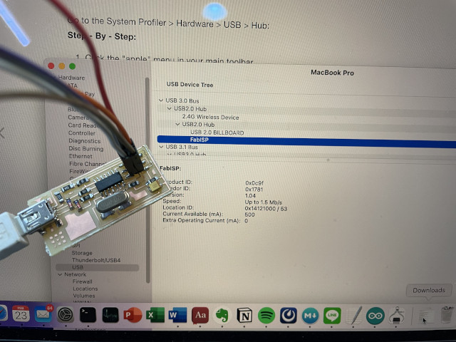
Hero shot: My first FabISP
Finally works! It shows on my USB port as FABISP!
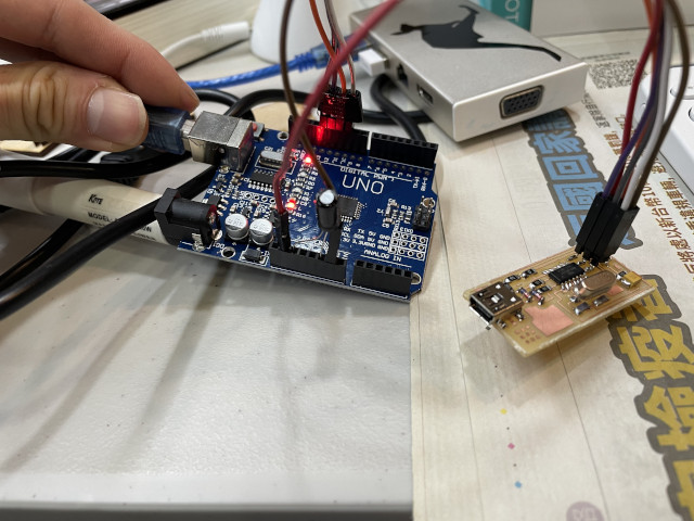
And I use arduino UNO to program it.
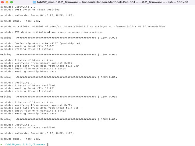
Record the moment “Averdude done. Thank you.”
Notes about milling, components, soldering
Learning list:
- CNC milling machine operation
- Electronic components recognition
- Soldering
- debugging
- Burn software
Before Asia review, I have some questions to ask:
- The copper line is too thin to see => Ans. Can use jimper line solve the problem
- The crystal in Taiwan is too long compare to the trace
- What does various kinds of USB matter?
Some soldering tips:
- Heat both the copper and component for several seconds (heat enough) and have tin on, it will automatically flow through them. Shiny and smooth.
- We don’t have 3 hands to hold iron, component (tweezer) and tin. So put some tin on one side of the copper fisrt, and when you solder it just mold tin and let it solid again. (If you are right hander, put tin on right hand side first, vice versa)
- Iron temperature matters… be sure the iron temperature enough or heat enough long.
- Solder from certer to outer, from complex to easy (number of legs), from low height to high.
Some knowkedge got:
- Electronic components has “SMD”, “THT” kind and different size of it (XXOO: XX for length, OO for width).
- If SMD size not fit, try “THT” and shorter its leg to fit in.
- Number of resistor meaning: how many zero behind it. 103 means 10000, 1002 mean 10000 the same.
- If copper line too thin, you can use tin to regenerate it.
- Check positive and negative side of components if available.
- Can use “L” shape pin header to make it easier to solder. Also can pull out the straight pin and replace it to make a customize one.
CNC milling
Parameter Note
Two kinds of millheads to transfer between traces and cut.
For Traces, we use mill traces (1/64) diameter: 0.4 mm speed: 2 mm/s (can be 3 mm/s) z: -0.2 mm
For cut, we use cut out board (1/32) diameter: 0.79 mm (maybe not the actual size of end mill) speed: 0.5 mm/s cut depth: 1.7 (update: can use type “3D rough” instead of “3D plane”, and cut depth 0.6 mm with bot z -1.7mm. Thus cut 3 times with one each down 0.6, we can increase the speed to 2mm/s)
Change endmill on MDX-20
This is a old version machine, so need to origin Z very carefully. Press “view” button til machine up, put on endmill, make sure it goes inside deeply and tight the screw. Press “view” button again, and press “down” until endmill get close to surface. Untight it, hold it carefully to let it down til touch the surface and tight it again.
Note: sometimes MDX-20 just keep repeating its previous task but not current task. If encounter this, shut down both computer and MDX-20, and restart them both.
Debug and burn boot loader
How to debug?
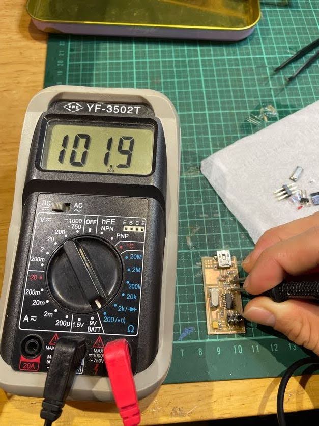 Use the bottom right blue area for resistor test. choose the one close to your ohm value but higher (Ex: test 499ohm should use 2k, 200 is lower).
If you touch both side of one resistor, the value show on screen should be the same. Between 2 resistors the be A+B etc.
Use the bottom right blue area for resistor test. choose the one close to your ohm value but higher (Ex: test 499ohm should use 2k, 200 is lower).
If you touch both side of one resistor, the value show on screen should be the same. Between 2 resistors the be A+B etc.
If you test 0 ohm resistor or just copper line, use 200 and the result should be a “BEEP” sound, which means the value is to low and that means works!
Note: still not sure how to test capacitor or crystal, many theory on the Internet but not confirmed.
How to burn boot loader?
You can find step by step tutorial here And also if you use arduino UNO, refer to this But the confusing part for me is this:
After(!) programming the arduino, connect a 10 uF capacitor between RESET and GND. I’m not sure what is that mean, even trying to solder the capacitor on arduino… Luckily, I found video that shows how, just need to plug in arduino pins!
 If you got this error messages, you need to install avr-gcc by:
xcode-select --install #make sure you have xcode
And run:
brew tap osx-cross/avr
brew install avr-gcc
If got error for avrdude, just brew install avrdude
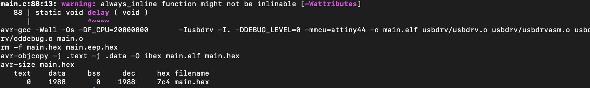 Note: One thing left is this, still not sure the warning matters or not?
well, maybe the easiest way to burn boot loader is through “burn boot loader” button in Arduino IDE tool tab, just remember to choose the right board, processor, clock (internal or external crystal: can check board design or makefile), port and programmer (USBtinyISP, if you use fabisp board)
Gallery
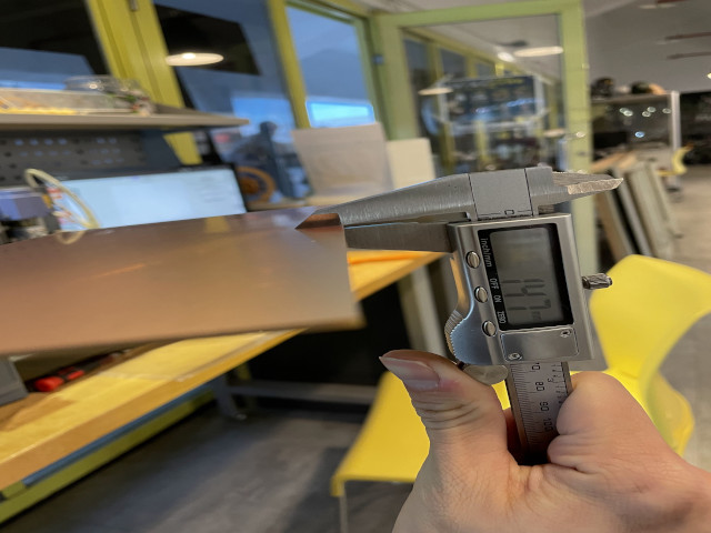
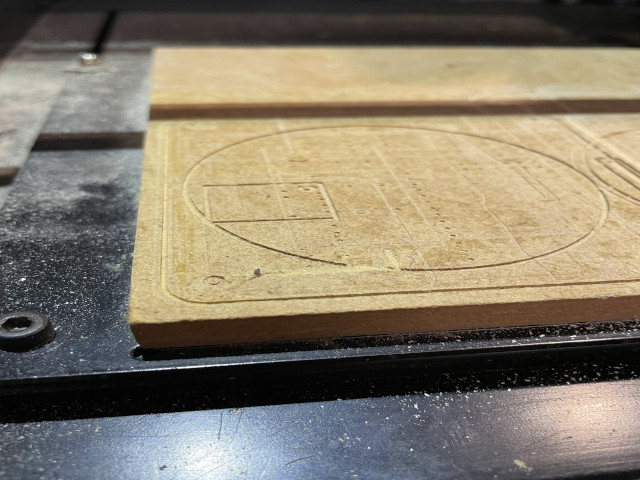
The material thickness.
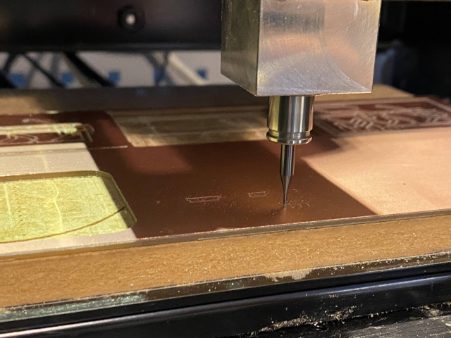
 This is milling looks like.
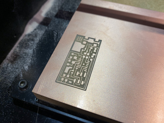
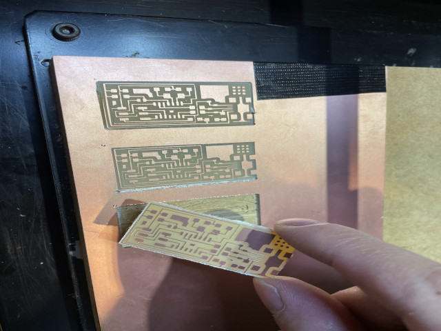
 And we got traces.
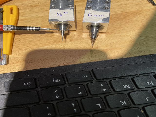
 Oh no, the end mill is broken.
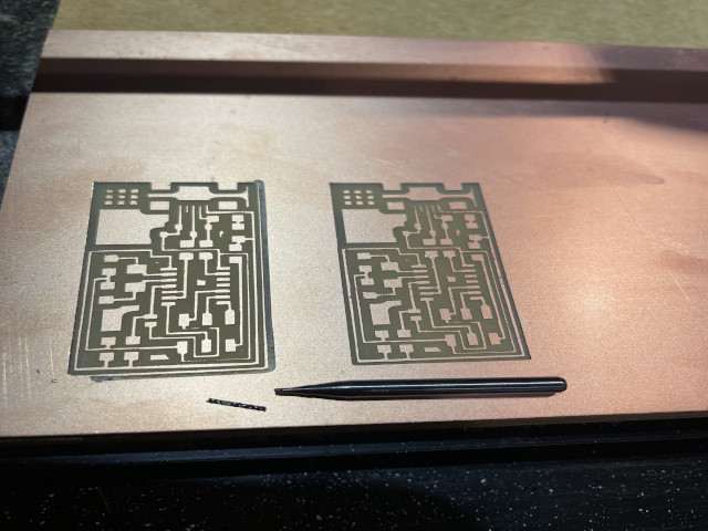
 After many fails, we got the right parameter and cut off.
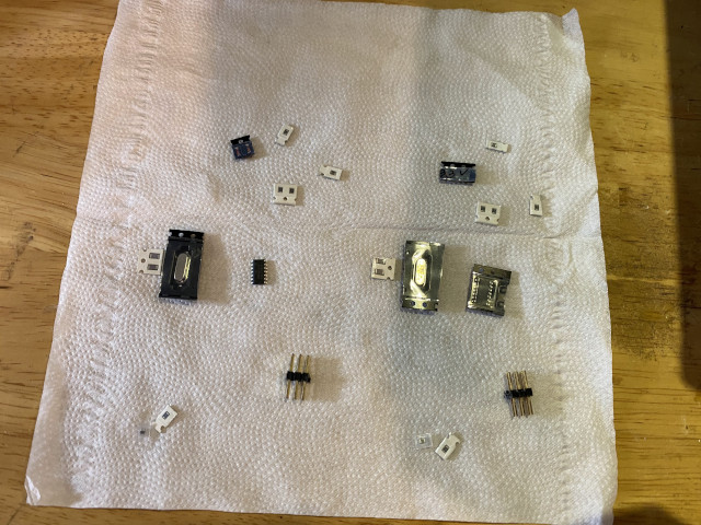
Next we need to find out all components (should be somewhere?)
 List what we have carefully on tissue.
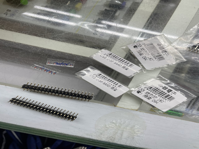
 Go shopping for the rest.
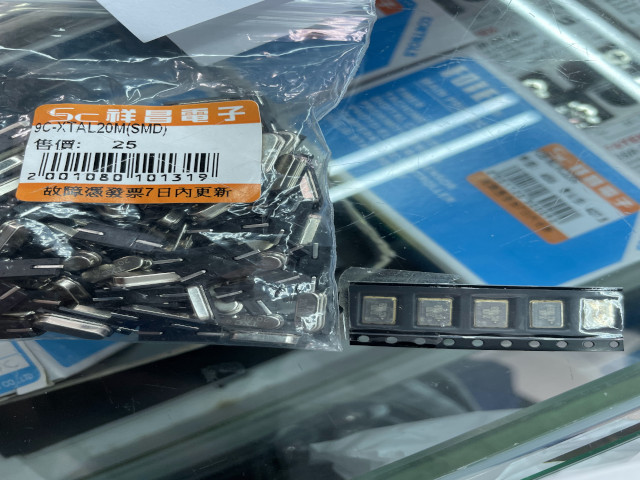
 And find different kind of crystals (not use in the end)
 Also the usb type confusing…

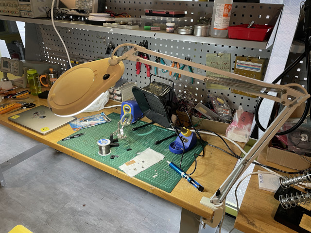
Next soldering. This is where we work.
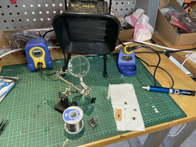
Try to solder tin and regenerate the disappearing copper line.
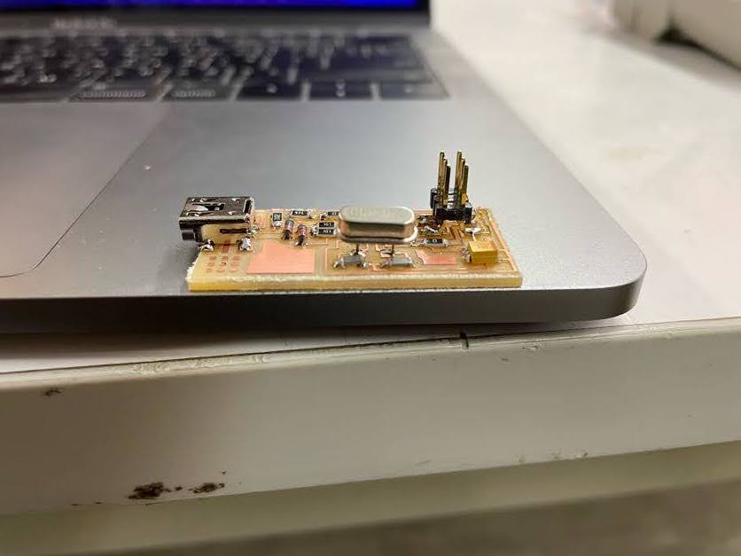
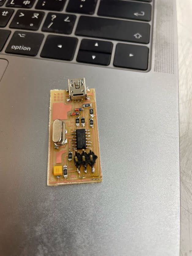 We finally use THT crystal and cut its pin shorter to fit in.
Useful links
- Install homebrew AVR
- Arduino bootloaders (not use this time)
- SMT / SMD Components & packages, sizes, dimensions, details
- Online resistor calculator
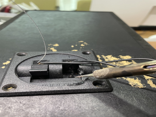
Side project: fix speaker
Got a old speak at home with two parts, connected with wires. But somehow one joint is broken and one wire cannot have stable connection.
To solve it once forever, I decide to solder it.