The first thing was to learn how the serial I2C bus works.
I2C is the same aas IIC which stands for Inter Integrated Circuit, it works with two wires and sends bits one at a time between a master device and a receiver device. Communication can be two way, but both master and slave devices have to have a way of knowing when to transmit. The devices are connected using two wires:
SDA >>>> stands for "serial data line" whcich transmits the bytes of your message, one bit at a time between frame bits and with start and stop condition bits. The devices pull it low to write the bits.
SCL >>>> stands for "serial clock line" which is constantly alternating between high and low voltage, at a constant speed therefore the devices always know when to expect a bit.
These two lines must always have pullup resistors, so that when they are idle, they are HIGH meaning that they are pulled to a 5V voltage.
Multiple devices can be connected to these two lines as long as at the end they have the pull up resistors. In order to have multiple devices, all of the devices must have an address. This address must be a 7-bit address number which means that the limit is 127 device addresses.
Arduino has a special library called Wire.h that works with the SAMD11C. We decided to connect several of our boards together in a network, and have them comunicate between them.
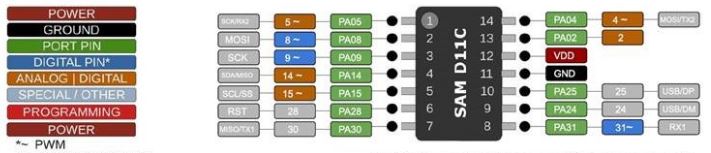
On the SAMD11C the pins for SDA and SCL are pins PA14 and PA15.
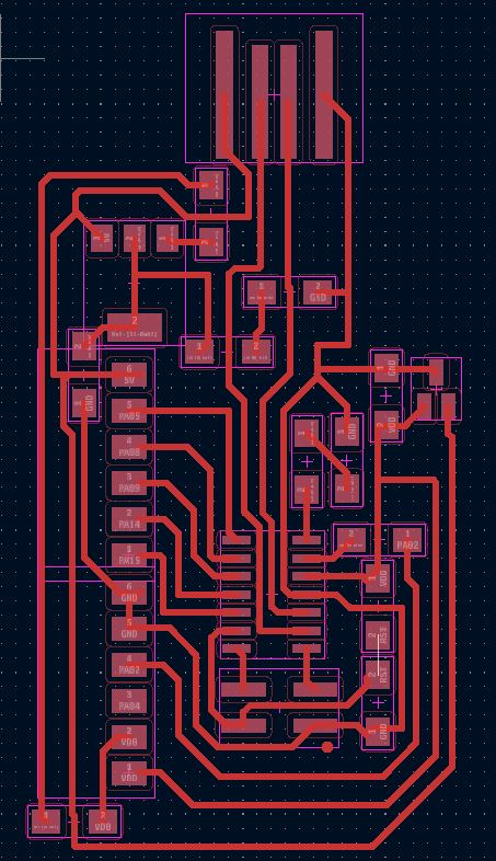
This is my board, you'll notice I just put some connectors in order to set up the I2C bus. I dod not include pull up resistprs, becase the SAMD has them internally.
The board was designed to be as small as possible.
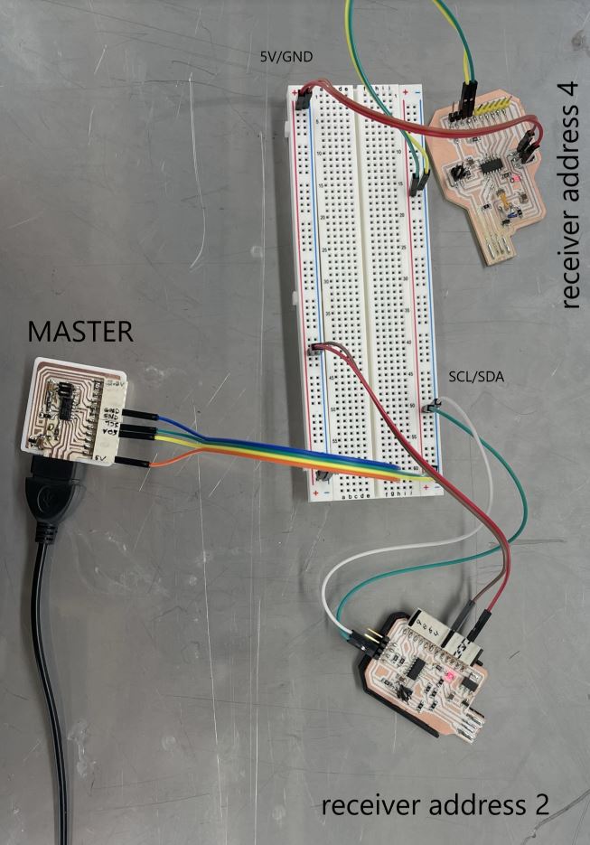
This is the wiring steup where we used a breadboard as a bus cable, both for the 5V and GND lines as well as the SDA/SCL lines.
Here you can see the I2C master receiving commands from serial on the computer, and then sends characters to each receiver board, which turn on their LEDs.
And here is the code for the master board which was my board. It's very simple. I initializes the I2C protocil, as well as the serial and when it receives certain letters from the computer, it sends specific characters to the receiver boards.
            #include <Wire.h>
              void setup() {
                Serial.begin(115200);
                Wire.begin(); // join i2c bus (address optional for master)
                pinMode(13,OUTPUT);
              }
              void loop() {
                while (Serial.available()) {
                  char c = Serial.read();
                  if(c=='H'){
                    Wire.beginTransmission(4);
                    Wire.write('H');
                    Wire.endTransmission();
                    Serial.println("writing to address 4!");
                  }
                  else if(c=='L'){
                    Wire.beginTransmission(4);
                    Wire.write('L');
                    Wire.endTransmission();
                    Serial.println("writing to address 4!");
                  }
                  else if(c=='G'){
                    Wire.beginTransmission(2);
                    Wire.write('H');
                    Wire.endTransmission();
                    Serial.println("writing to address 2!");
                  }
                  else if(c=='K'){
                    Wire.beginTransmission(2);
                    Wire.write('L');
                    Wire.endTransmission();
                    Serial.println("writing to address 2!");
                  }
                }
              }
I2C explanation
And here is the code for the receiver boards. When they receive a specific character, they turn their LEDs on.
                #include  //library for I2C
                  byte own_address = 4; //set own adress, changed to 2 in another board.
                  void setup() {
                    Wire.begin(own_address); //enter the bus on specified address
                    Wire.onReceive(receiveEvent);
                    pinMode(2, OUTPUT);
                    digitalWrite(2, LOW);
                  }
                  void loop() {
                  }
                  void receiveEvent(int howMany) {
                    while (Wire.available()) {
                      char c = Wire.read();
                      if(c=='H'){
                        digitalWrite(2,HIGH);//turn LED on
                      }
                      else if(c=='L'){
                        digitalWrite(2,LOW);//turn LED off
                      }
                    }
                  }
I2C with Digispark and Arduino
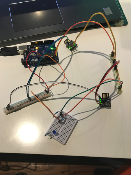
Wiring
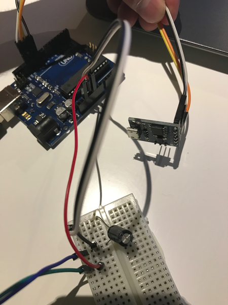
I connected the two digisparks to the SDA and SCL pins on the arduino, they were connected with two 4.5KOhm pull up resistors. Connected to the 5V on the arduino. Also, I provided 5V power and GND to the digisparks from the arduino. On an UNO, SDA is the A4 pin and the SCL is the A5 pin. These are the only pins you can use for I2C.
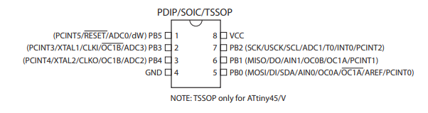
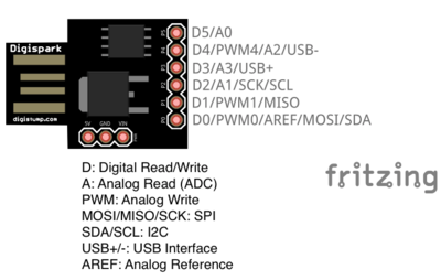
On the ATtiny, the SDA pin is PB0 or pin 5, while the SCL pin is the PB2 or pin 7. These are marked on the digispark accordingly.
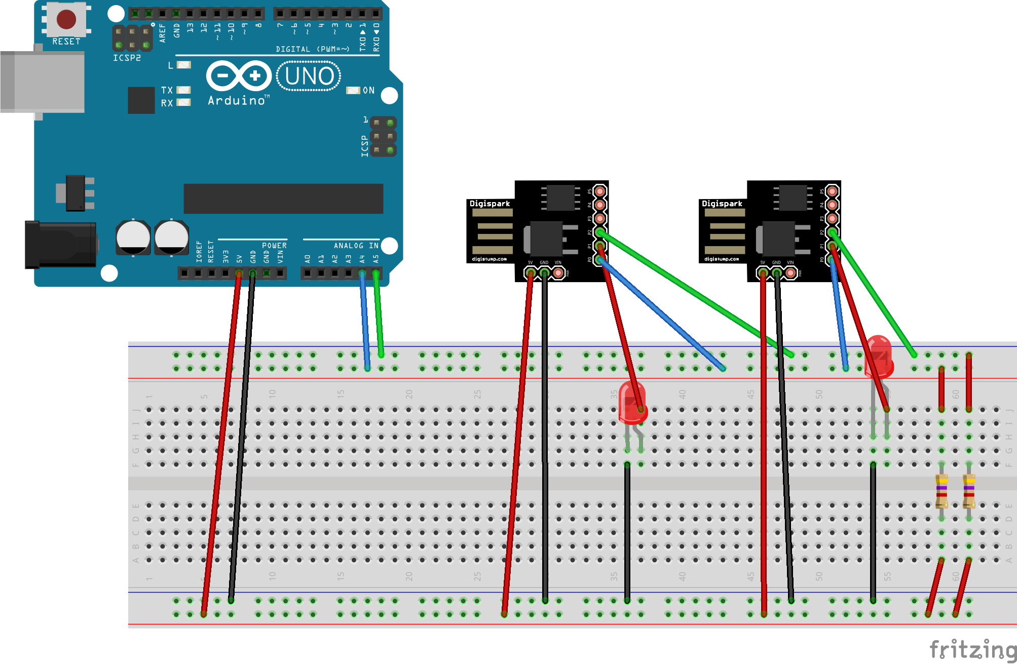
The image is a bit of a mess, but this is a diagram of what I connected. I am starting to use fritzing to prototype these boards:
Each LED is controlled on the digispark's pin 1 which is the pin 6 or PB1 on the ATtiny85.
I2C code for Arduino Master
Arduino has a library for this protocol and communication which must be used on specific pins because the SCL and SDA lines refer to specific registers on the board's microprocessor. The Wire library, as it is called parses and deals with the timing and addressing, transmitting and recieving of data.
To include this library, you have to use this at the top of the sketch:
#include <Wire.h>
I will use anArduino UNO to be the master to which the two digisparks are connected. The important methods to use with the Arduino master are these:
Wire.begin()>//initialize the I2C when no address is provided thatmeans you are the Master.
Wire.beginTransmission(byte of address)//you are writing to an address always.
Wire.write()//you write bytes as ints, characters or strings.
Wire.endTransmission()//you are done sending and someone can take over the line.
So the idea is with these codes, send the data from the Master. This is the code the master is using, note that I'm using serial to send commands from the computer and according to these commands, I'm writing to different addresses, in this case I used addresses 8 and 9.
          #include <Wire.h>
          void setup() {
            Serial.begin(9600);
            Wire.begin(); // join i2c bus (address optional for master)
            pinMode(13, OUTPUT);
          }
          void loop() {
            while (Serial.available()) {
              char c = Serial.read();
              if (c == 'H') {
                Wire.beginTransmission(9);
                Wire.write('H');
                Wire.endTransmission();
                Serial.println("writing to address 9!");
              }
              else if (c == 'L') {
                Wire.beginTransmission(9);
                Wire.write('L');
                Wire.endTransmission();
                Serial.println("writing to address 9!");
              }
              else if (c == 'G') {
                Wire.beginTransmission(8);
                Wire.write('H');
                Wire.endTransmission();
                Serial.println("writing to address 8!");
              }
              else if (c == 'K') {
                Wire.beginTransmission(8);
                Wire.write('L');
                Wire.endTransmission();
                Serial.println("writing to address 8!");
              }
            }

          }
Code on the Digispark Slave
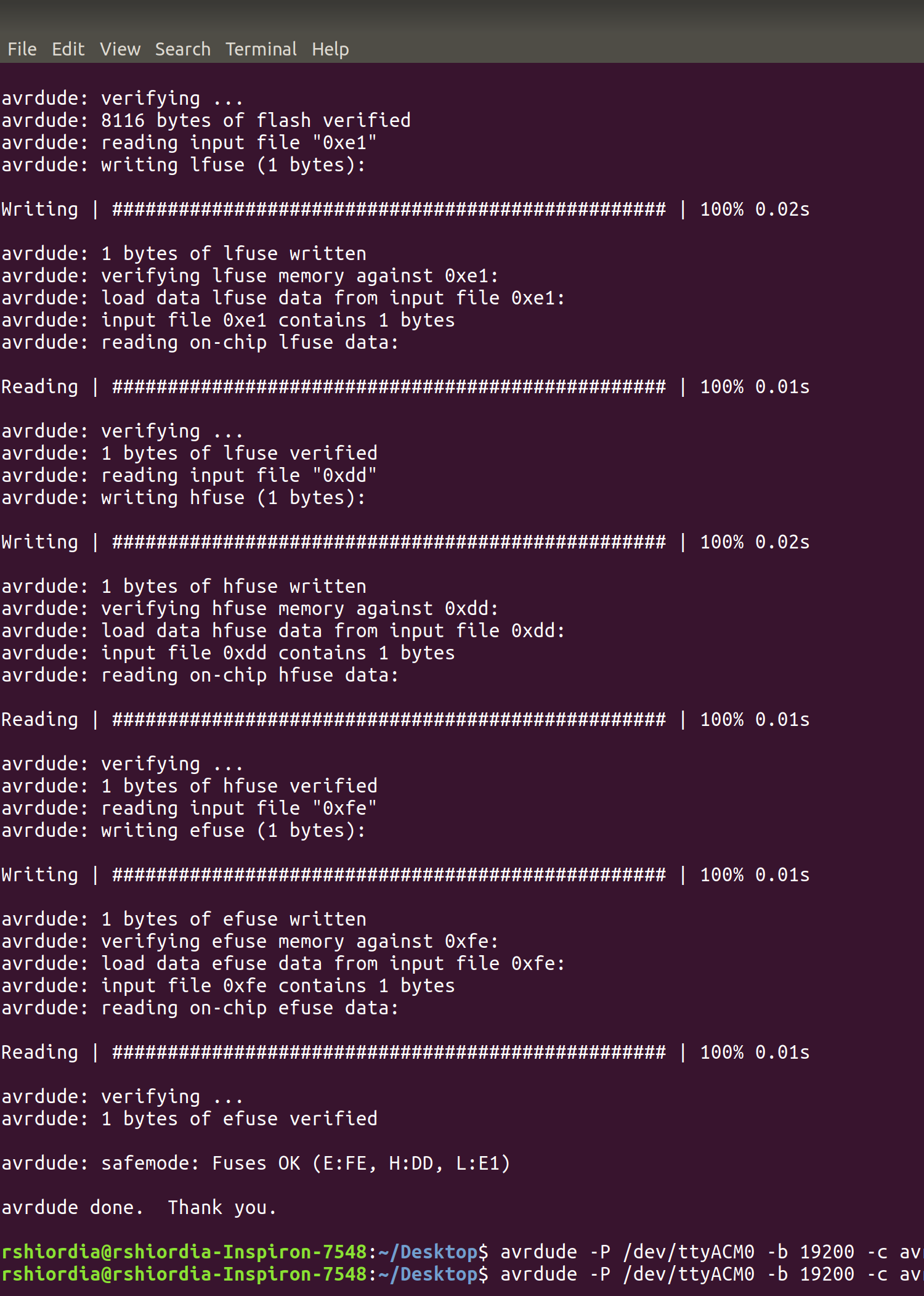
This was the hard part. First of all. The ATtiny85 does not have USB pins, nut it uses a USB connector to be programmed from the Arduino IDE. The board does this by using a special bootloader that does software USB. This bootloader is called micronucleus and can be found here. During prototyping, something went wrong and one of the boards could not be programmed no matter how hard I tried. I had to re-upload the micronucleus bootloader by following this tutorial. I used avrdude from ubuntu terminal to upload the appropiate hex file using the arduino as ISP sketch. Once I had the correct Hexfile (t85_default.hex), and the Arduino ISP loaded to the UNO(this sketch must be loaded without the capacitor you see there) I went ahead with this command on the terminal:
avrdude -P /dev/ttyACM0 -b 19200 -c avrisp -p attiny85 -Uflash:w:./t85_default.hex:i -U lfuse:w:0xe1:m -U hfuse:w:0xdd:m -U efuse:w:0xfe:m
This is the avrdude log:
TinyWire library
The Wire library is not compatible with the digispark because the ATtiny uses different pins to do I2C also, that library includes other Arduino chipsets that would load up a lot of memory on the ATtiny85's limited 8Kb. The solution is a modified library called TinyWire which can be found here. There are several versions of this library, but the one linked has both master and slave capabilites and is the one most similar to the Wire library from Arduino. After downloading it, as well as setting up the digispark core for the Arduino IDE, you can set it all up propperly. Here is the final code that was running on the development boards. Note that this code was uploaded to each of the two boards using 8 and 9 addresses respectively.
          #include <TinyWire.h> //Se inicia la librería TinyWire
          byte own_address = 9; //Dirección del Digispark en el bus I2C
          void setup() {
            TinyWire.begin(own_address); //Se entra al bus I2C en la direccion 10
            TinyWire.onReceive(receiveEvent);
            pinMode(1, OUTPUT);
            digitalWrite(1, LOW);
          }
          void loop() {
          }
          //Cuando se reciba la peticion, se imprime "hola" en el bus I2C
          void receiveEvent(int howMany) {
            while (TinyWire.available()) {
              char c = TinyWire.read();
              if(c=='H'){
                digitalWrite(1,HIGH);
              }
              else if(c=='L'){
                digitalWrite(1,LOW);
              }
            }
          }
Success!
The video shows how I-m sending letters to the arduino master device, and this one in turn sends characters to the digispark slave devices. On the baove code, each serial command was paired with an I2C command to a slave device.
Each command turns on an LED connected to the Attiny boards. note that these boards have a red built in LED connected on the same pin so you can see both the external I connected and the built-in LED turn on as I type 'H', 'G' to turn on, and 'K','L' to turn off each slave device.
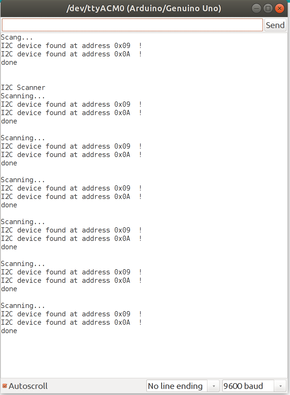
I2C Scanner
Another important step which I forgot to mention was to use the I2C scanner from here which will tell you the addresses of any I2C devices that are connected to the arduino. The code loops through all of the 127 addresses, and if the device responds, it lets you know on the serial monitor. The image from the serial monitor shows it found devices at address 0x09 and 0x0A which correspond to address numbers 9 and 10 respectively. These were the ones I initially gave the digisparks.
For another communication excercise I decided to try to use sockets and send messages through UPD. I copied Neil's python code and adapted it to python3 which is what I am using. I only had to use .encode('utf-8') on the sender message in order to read it propperly because for some reason it wouldn't work. Here is a quick video:
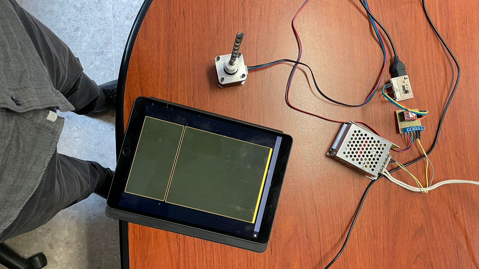
Networking a Stepper motor with the iPad using Touch OSC
Touch OSC Interface on the iPad!!!
I think that my assignment for interface programming would also apply for networking because this sends messages from an ipad to my board through IP using OSC protocol.
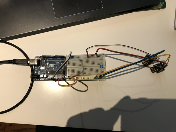
This was my setup:
I have everything connected like this:
The ipad has a custom GUI that I made using Touch OSC Editor.
It sends Messages to the computer via WiFi.
The computer is receiving the messages in Processing using OSCP5, a special library that receives and parses the messasges.
The computer is sending serial messages to a custom SAMD11C board.
The SAMD11C board is sending pulses to a custom stepper driver module with a Pololu A4988.
The driver is pulling power from a 25V power supply.
The stepper is moving according to the driver's pulses
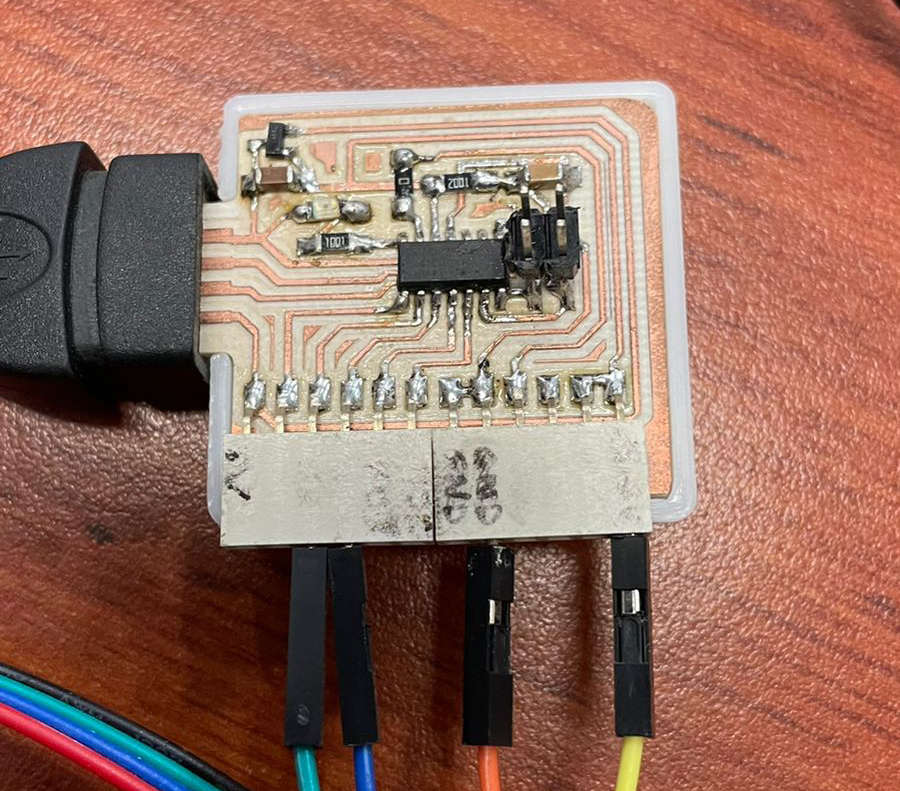
This is the controller board:
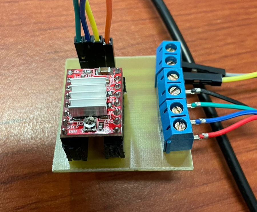
This is the stepper driver module:
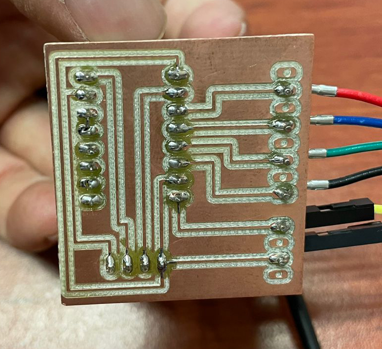
This is the back of the driver module:
Touch OSC
TouchOSC is an implementation of Open Sound Control made by Hexler. It is an app to design and use control surfaces on iOS and Android. It sends and receives Open Sound Control or MIDI messages over WiFi. It also comes with the ability to create your own control surfaces or GUIs that you can configure using their free editor.
The first thing you do is download the app, which you can find on the app store.
What I did is to send messages from my iPhone or iPad to my laptop via WiFi using this app. The laptop then sends messages to my board using serial connection.
Once you have the app, you can connect to your computer using the computer IP address.
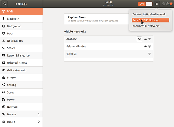
Since I was here at the university on the wifi network, I decided to create my own local area network.
Using my Ubuntu system, I went to my WiFi settings and activated a local network using Turn On Wi-Fi Hotspot
You can do this on any WiFi network, but it's just easier and safer to send the messages over a local area network.
After this, you connect the phone to this wifi using the provided password. Neither the phone nor the computer will have internet access after this point.
Once the phone is connected, you open the app, and connect to the computer using the computer's IP address.
in my case I just read the address from terminal using
ip address
To connect to the host computer on the app, you open the app, and then you just input the IP address of the computer under the Host Name field.
You'll notice that there is already an Interface loaded there. There are loads of examples with many different options.
Creating your Touch OSC interface using TouchOSC Editor
I used the editor in their webpage to create a very simple GUI that sends two values: an on/off value and a speed value that will be used by the stepper motor.
Once you download the editor you just start a new file, set up the resolution, and create objects.
In my case I created a vertical fader object called fader1. I alse created a toggle button named toggle1. The fader's values will go from 500 to 20,000 which are the values I 'll use on the arduino side.
This interface is then loaded to the phone by pressing the sync buttom. On the app side, you tap "add" on the layout selector, and then add the Host IP address, it will download the interface you're working with.
Listening to messages from touchOSC using Processing OSCP5 library
Once you have done all this, you can start sending messages.
Processing takes care of this, but it could be done in python or some other programming language.
You have your phone connected and every time you do something on the control surface of the phone or tablet, it sends an OSC message that the library OSCP5 interprets as an OSC event.
At first it's hard to parse the messages because you don't know if you are receiving, that's why I reccommend to use the examples from OSC p5. They will print to processing's console and you'll start to figure it out from there. And be very careful with the addresses and port numbers.
of particular help is void oscEvent(OscMessage theOscMessage) which in the examples will print the type of event and some information that helps a lot.
I used the plug method to attach a function for the fader1 and toggle1. So every time you do something with them it reads the value of these elements in the GUI.
And here is the code for the processing side:
note that I am importing two libraries: OSCP5 and Processing's built in Serial library.
                    /**
                    *Sketch by Rodrigo Shiordia Based on oscP5plug and crontrolp5 examples by andreas schlegel
                    fabacademy 2022 interface and application programming
                    */
                    import oscP5.*;
                    import processing.serial.*;
                    OscP5 oscP5;
                    Serial myPort;
                    int c =color(255);
                    boolean on=false;
                    int knobValue=5000;
                    void setup() {
                      size(400, 400);
                      String portName = Serial.list()[0];
                      println(portName);
                      myPort = new Serial(this, portName, 115200);
                      frameRate(25);
                      oscP5 = new OscP5(this, 8000);
                      oscP5.plug(this, "toggle", "/1/toggle1");
                      oscP5.plug(this, "slider", "/1/fader1");
                    }
                    void draw() {
                      background(c);
                    }
                    void oscEvent(OscMessage theOscMessage) {
                      if (theOscMessage.isPlugged()==false) {
                        println("### received an osc message.");
                        println("### addrpattern\t"+theOscMessage.addrPattern());
                        println("### typetag\t"+theOscMessage.typetag());
                      }
                    }
                    void toggle(float theValue) {
                      if (theValue==1.0) {
                        String s="H,"+knobValue+";";
                        myPort.write(s);
                        on=true;
                        c=color(255);
                      } else if (theValue==0.0) {
                        String s="J,"+knobValue+";";
                        myPort.write(s);
                        on=false;
                        c=color(0);
                      }
                      println(on);
                    }
                    void slider(float theValue) {
                      println(theValue);
                      int speed=int(theValue);
                      knobValue=speed;
                      String s="H,"+knobValue+";";
                      if (on) {
                        myPort.write(s);
                      }
                    }
The code on the arduino parses the serial message that Processing sends, and updates the stepDelay variable. note that Processing is sending things on this format: H,700;
Arduino will read this string until it reaches ; , it will then split the string on the comma , and read the first part which will be "H" or "J". These letters will tell to turn the stepper on or off.
Then Arduino code will assign the number after the comma, and assign it to stepDelay.
                    int pulPin = 8;
                    int dirPin = 9;
                    int ledPin = 5;
                    int stepDelay = 700;
                    boolean on = false;
                    void setup() {
                      Serial.begin(115200);
                      pinMode(ledPin, OUTPUT);
                      pinMode(pulPin, OUTPUT);
                      digitalWrite(pulPin, LOW);
                    }
                    void loop() {
                      while (Serial.available()) {
                        String cmd = Serial.readStringUntil(';');
                        int comma = cmd.indexOf(',');
                        String stepVal = cmd.substring(0, comma);
                        if (stepVal == "H") {
                          on = true;
                        }
                        else if (stepVal == "J") {
                          on = false;
                        }
                        String stepSpeed = cmd.substring(comma + 1, cmd.length());
                        int val=stepSpeed.toInt();
                        if (val > 1) {
                          stepDelay = stepSpeed.toInt();
                          break;
                        }
                      }
                      if (on) {
                        digitalWrite(pulPin, LOW);
                        digitalWrite(ledPin, LOW);
                        delayMicroseconds(stepDelay);
                        digitalWrite(pulPin, HIGH);
                        digitalWrite(ledPin, HIGH);
                        delayMicroseconds(stepDelay);
                      }
                    }


 Once you have the app, you can connect to your computer using the computer IP address.
Since I was here at the university on the wifi network, I decided to create my own local area network.
Using my Ubuntu system, I went to my WiFi settings and activated a local network using Turn On Wi-Fi Hotspot
Once you have the app, you can connect to your computer using the computer IP address.
Since I was here at the university on the wifi network, I decided to create my own local area network.
Using my Ubuntu system, I went to my WiFi settings and activated a local network using Turn On Wi-Fi Hotspot