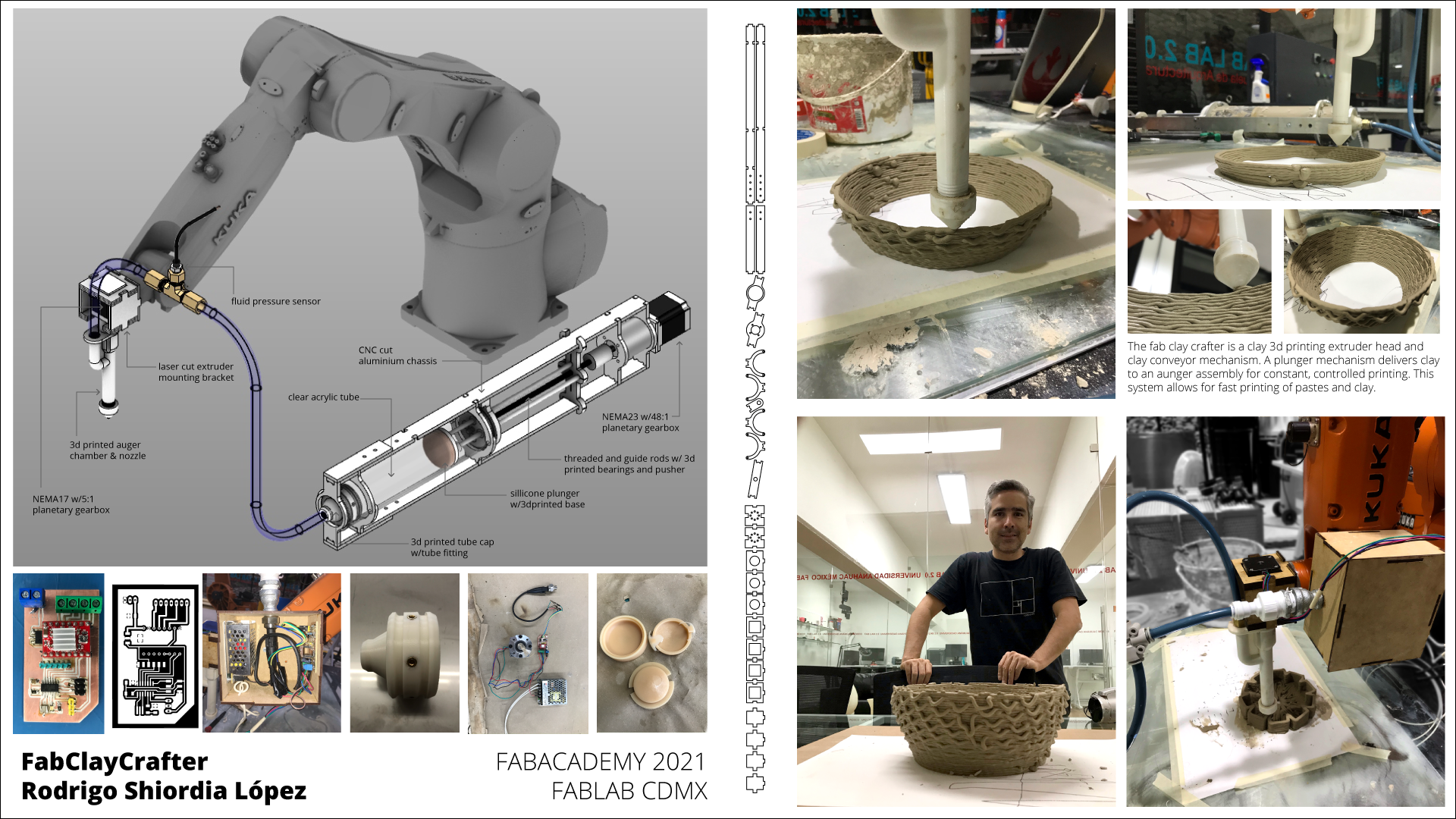
FINAL PROJECT DESCRIPTION
This is my final project. It consists of a clay extruding system for use with our kuka KR6 robotic arm.
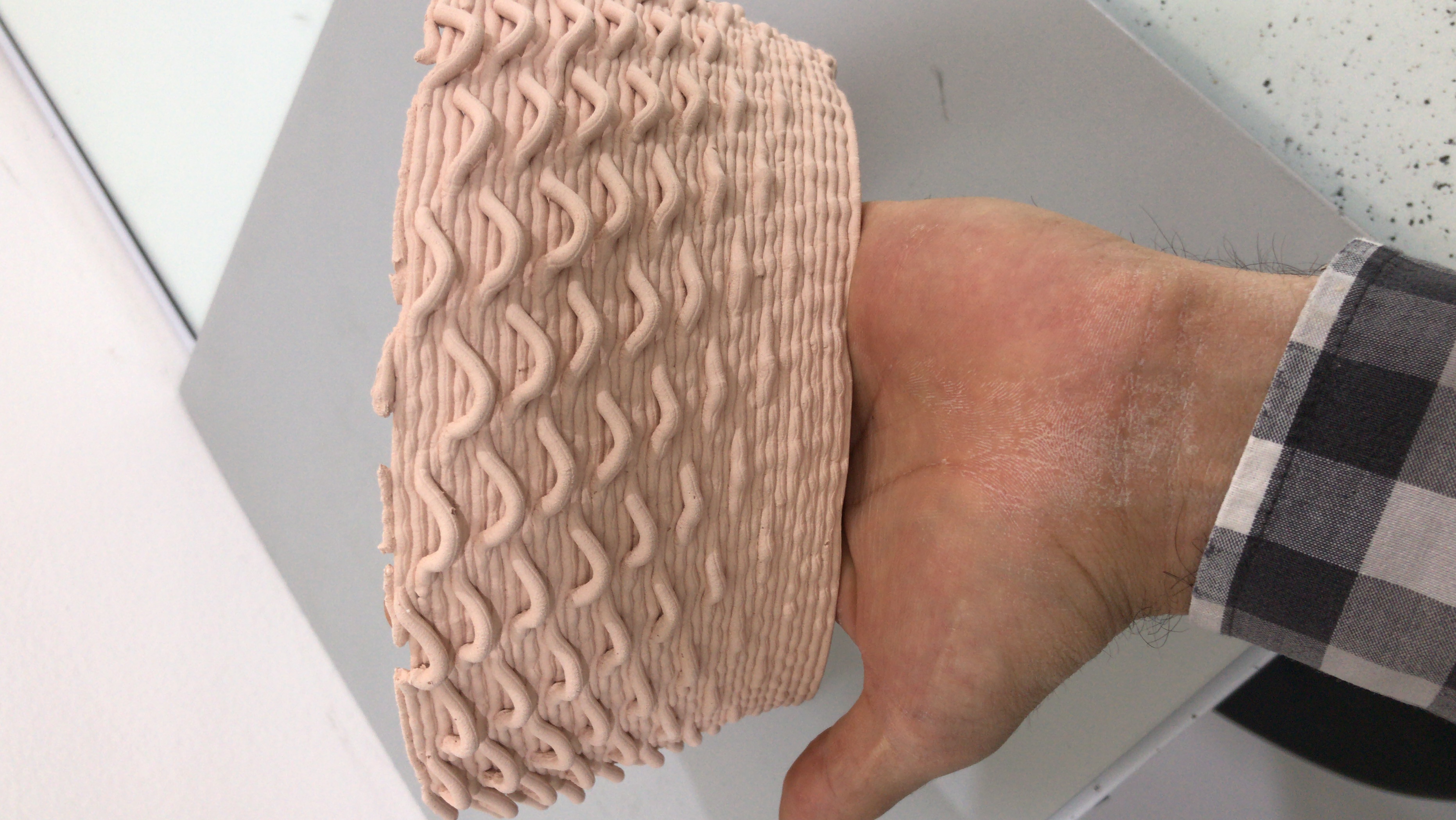
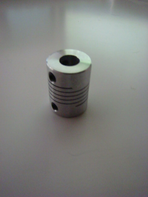
This is a printed piece I made with it:
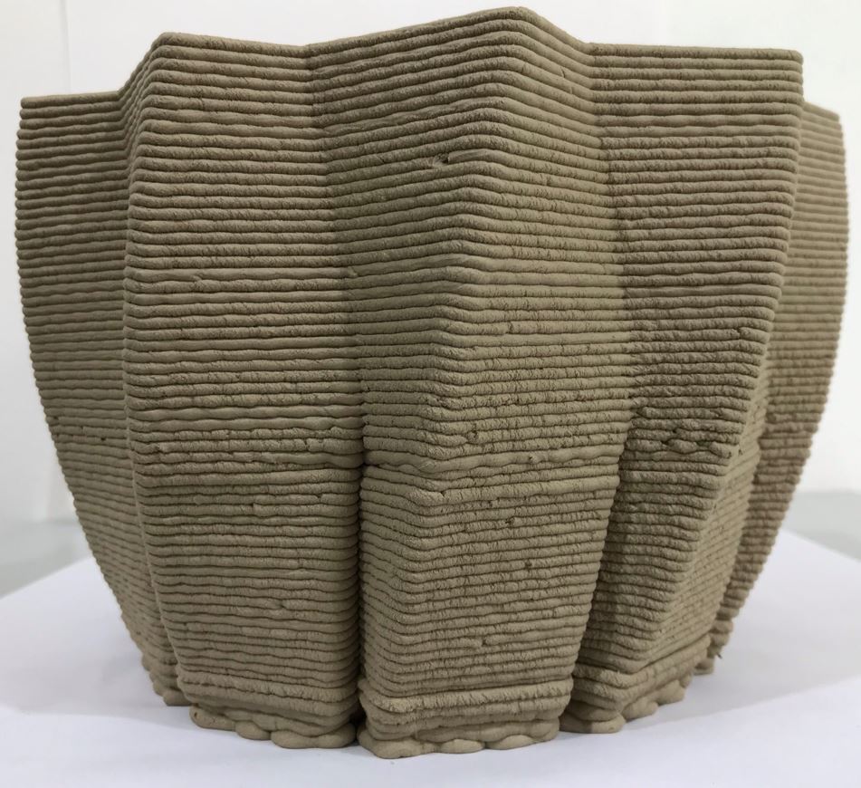
This is the fired print, which Neil asked me to see when I presented back in 2021.
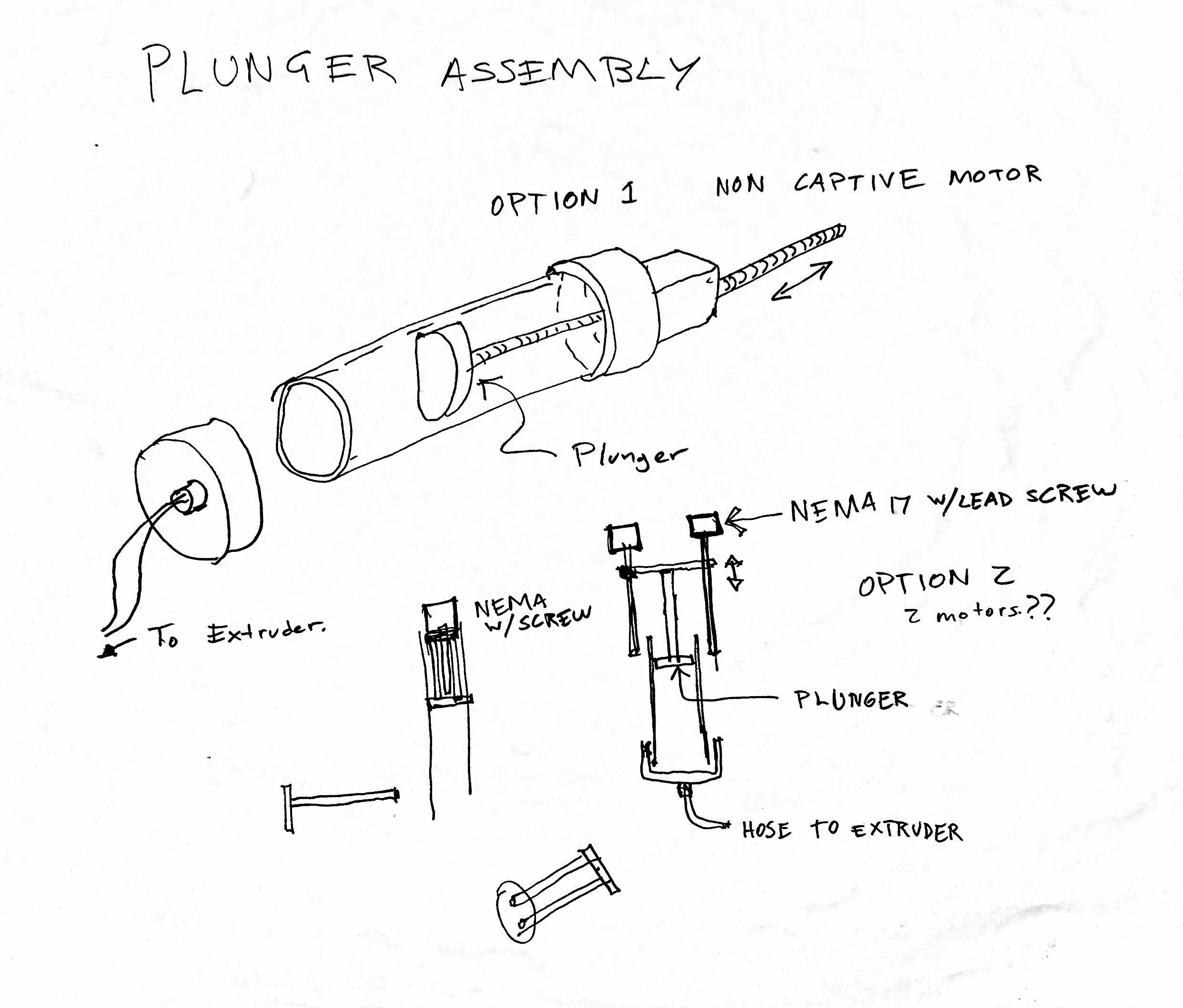
Notes and sketches on the Final Project
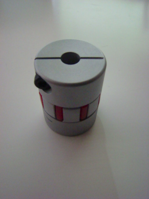
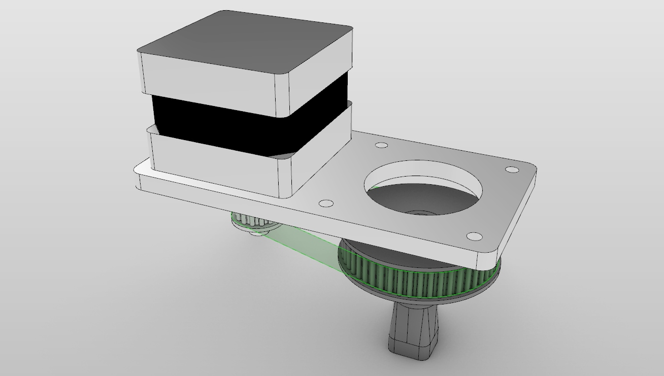
The basic idea is to have pressurized clay come into a tee fitting that I can machine out of brass(I have some experience with metal machining and lathe turning). Inside the tee fitting there will be a screw that rotates and pushes the clay downwards through the nozzle piece that can rotate while attached to a belt and pulley system. The nozzle will be 3d printed to allow for easy testing and swift interchangeable designs.
There are two important areas of focus: the first is the end mechanism that does what is described in the diagram, and the second is the mechanism that provides the pressurized clay. I'll try to develop those in parallel and hopefully finish both, but the plan is that the project could work with either of the two systems.
Developing the design
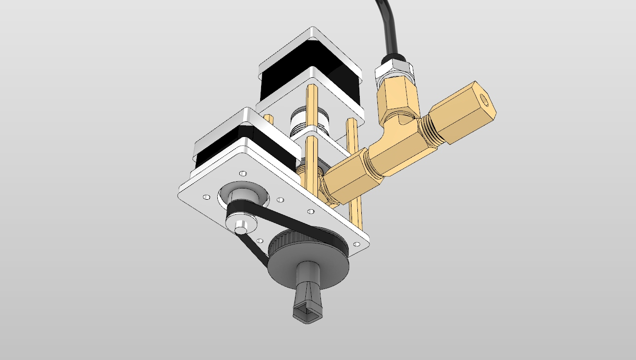
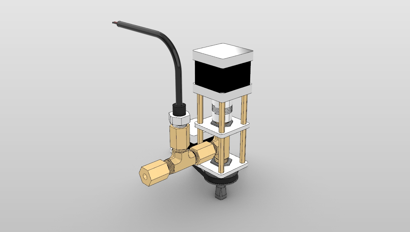
Extruder Assembly
In reality there are two tee fittings that are attached to the extruder. One is to receive the pressurized clay, and the other is to connect an analog pressure sensor. So far I've found one model that can measure pressure of air, water, and non corrosive oils, so I believe that this is a nice feedback snesor to have. I will have the data sheet shortly. Supposedly it measures up to 174 psi, which I think is well in range. Most painting compressors operate like at 50psi, so I'm thinking that doubling that is not a problem. I also doubt that the plunger can produce those pressures. If I don't finish the plunger, then I'll provide pressure with an air compressor and possibly attach an electrovalve.
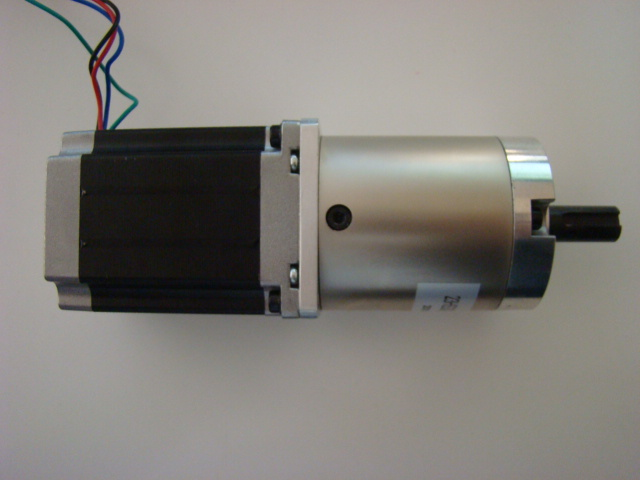
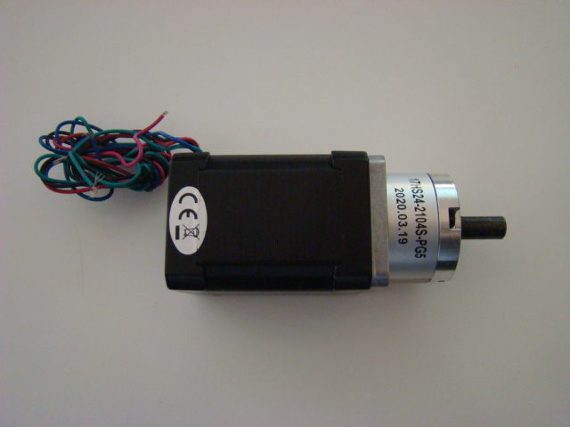
The plunger system that provides the pressure is a stepper motor attached to a lead sccrew, and two guide rodds attachedd to a 3d printed plunger head. This is an animation of this motion. Hopefully the mechanical design is fine.
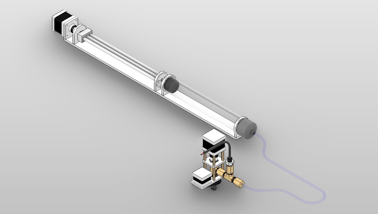
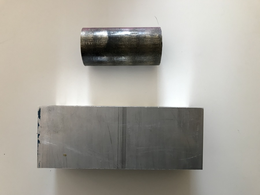
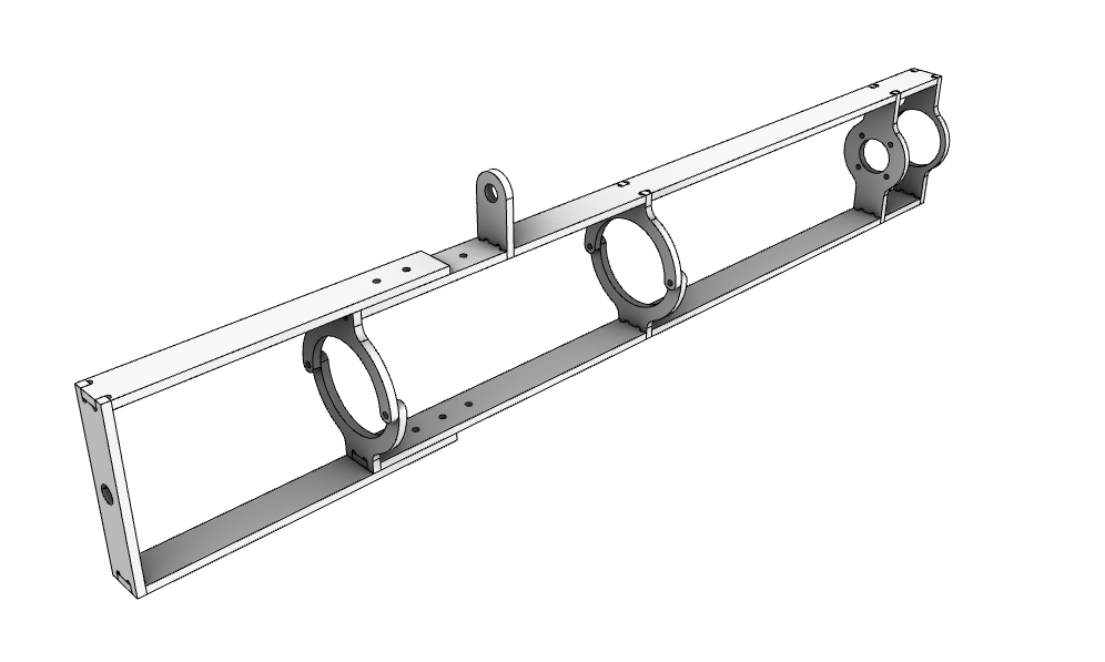
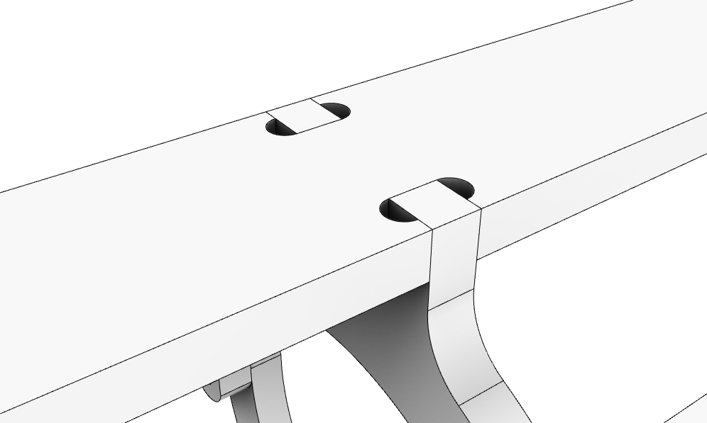
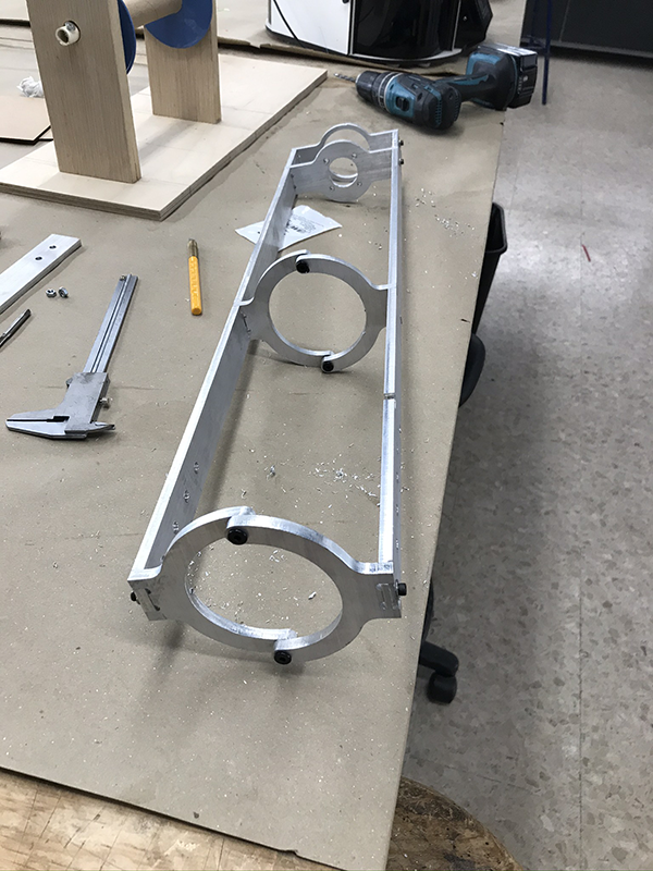
I have changed my plunger design for a larger 3 inch diameter tube. I have also started to medel the CNC aluminium pieces along with tabs and holes for all screws. so far I have the motor and tube mount. I did this once I had the motor and tube physically so that I could be sure of all the dimensions.
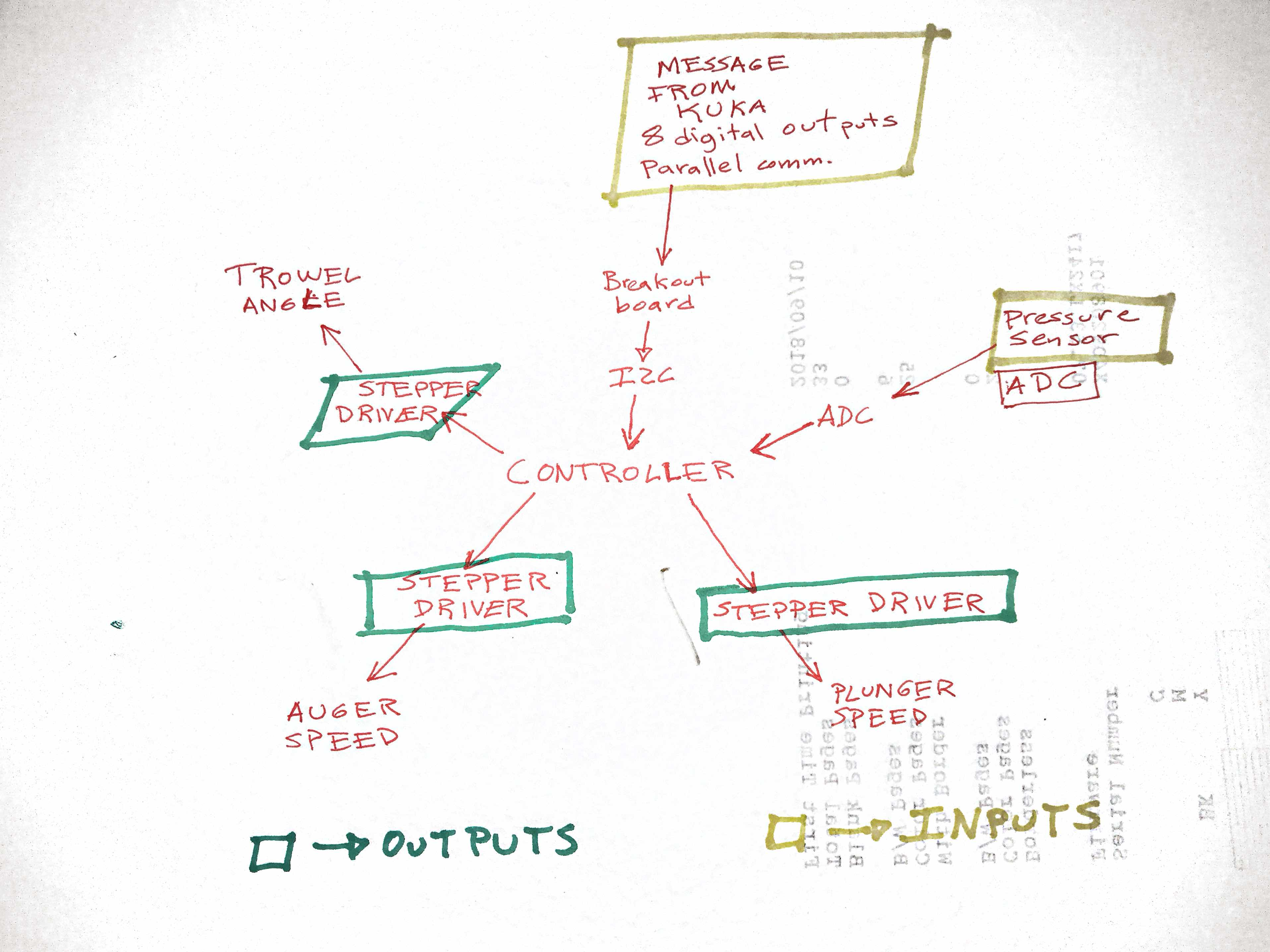
This is the whole system integration diagram.
Materials and Components
This is the current Bill of Materials (BOM). It details vendors, price, and quantities. Will be updatedd as the project progresses.
I have started to receive materials ordered, first I got the clear acrylic tube, which I cut into three parts.
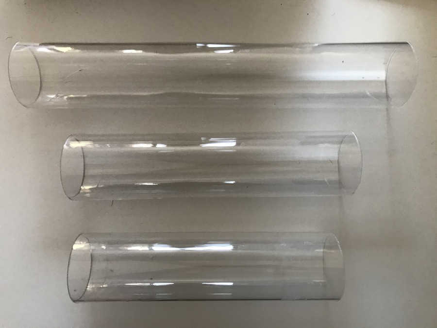
 .
.
Project Plan
So far, I've done much of the CAD work and the parts list for the mechanical design. I wil use the coming 3 weeks to fabricate all of that and start designing and sourcing the electronics.
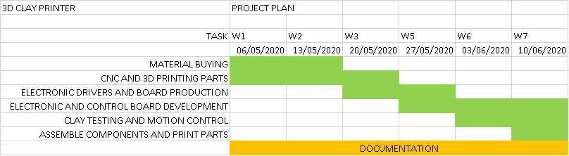
Here is my current project plan:
Electronics Design and Production
My electronic system consists of a pololu A4988 stepper driver and an ATTiny44 that controls the stepper and receives input from the pressure sensor. More on this phase can be found at input and output devices
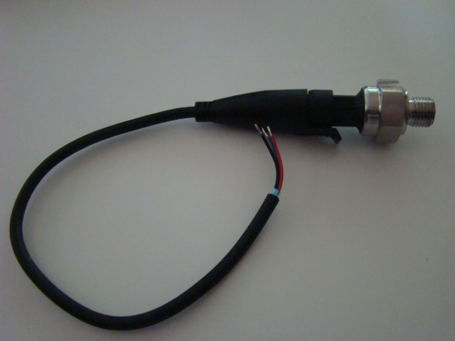
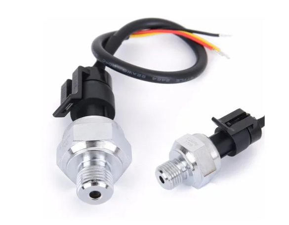 This is the analog pressure sensor.
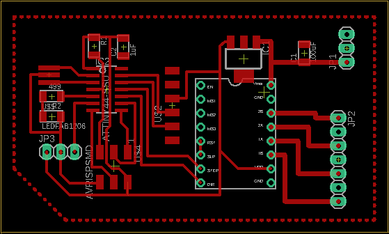
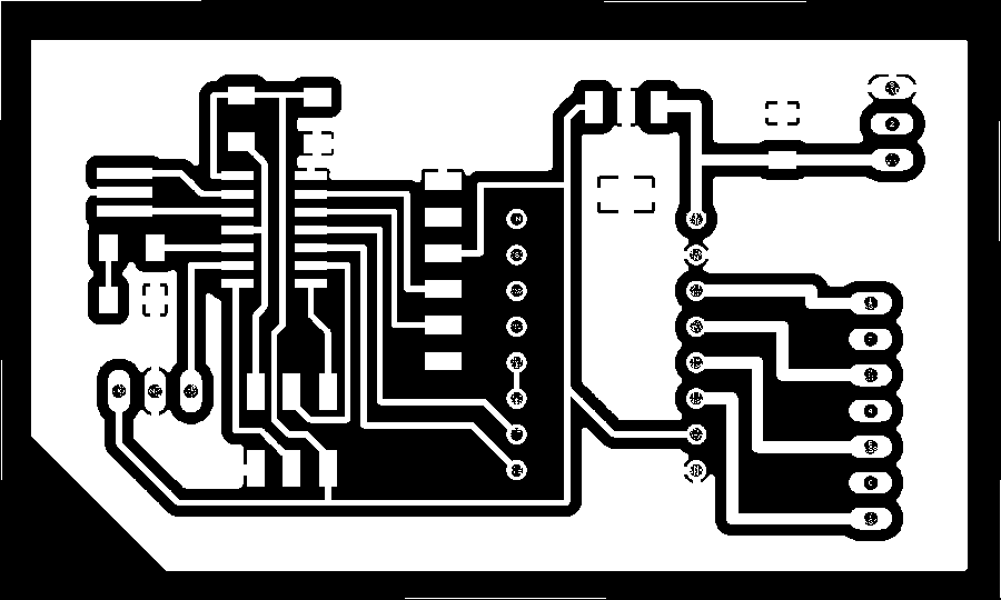
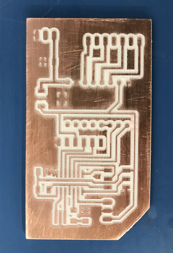
This is the board I designed. It makes the pulses for the driver from an ATTiny44.
It uses a serial interface to receive commands from the computer. More on this on the networking and communication page or the interface and application programming page.
Here is the schematic image:
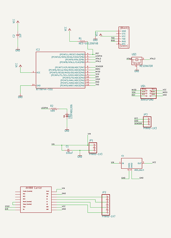
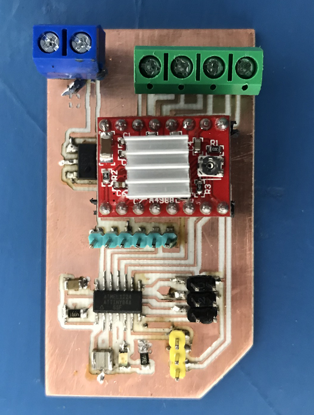
The board also has a mount for a pololu A4988 that drives the board. The regulator takes voltage from the power supply and converts it to 5V to drive the attiny.
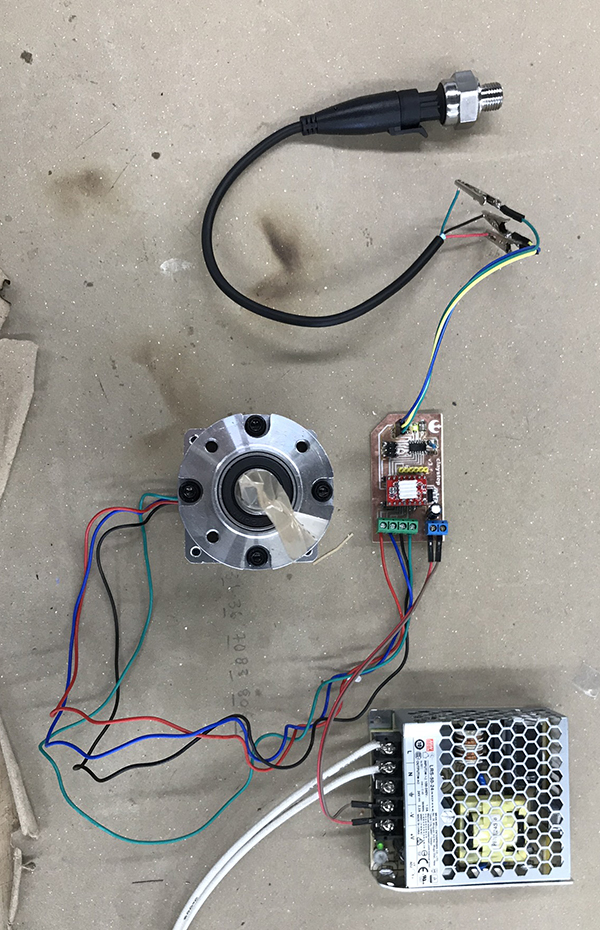
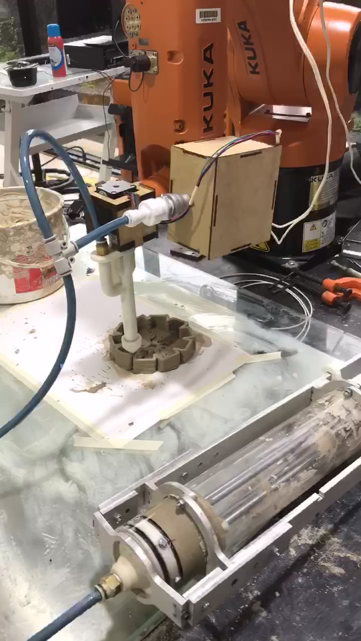
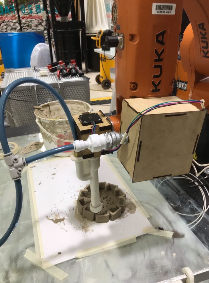
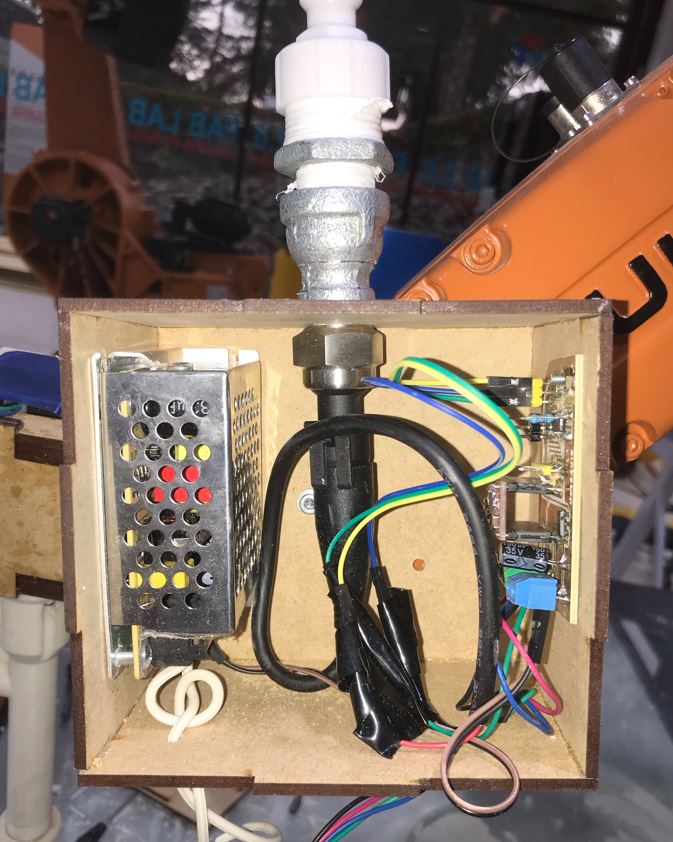
Here is all the electronics on the packaging box I made that is mounted to the kuka robot.
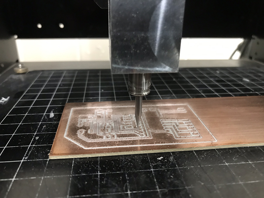
As you can see, the pressure sensor is working, and the motor as well. It actually took me 3 redesigns of the board, as well as several tries at soldering correctly.
The final code uses the pressure sensor as a security cutoff.
Here is the Final Arduino Code:
                int pulPin = 8;
                int dirPin = 9;
                int ledPin = 5;
                int stepDelay = 700;
                boolean on = false;
                int sensor=A7;
                int sensorValue=0;
                void setup() {
                  Serial.begin(115200);
                  pinMode(ledPin, OUTPUT);
                  pinMode(pulPin, OUTPUT);

                  digitalWrite(pulPin, LOW);
                }
                void loop() {
                  while (Serial.available()) {
                    String cmd = Serial.readStringUntil(';');
                    int comma = cmd.indexOf(',');
                    String stepVal = cmd.substring(0, comma);
                    if (stepVal == "H") {
                      on = true;
                    }
                    else if (stepVal == "J") {
                      on = false;
                    }
                    String stepSpeed = cmd.substring(comma + 1, cmd.length());
                    int val=stepSpeed.toInt();
                    if (val > 1) {
                      stepDelay = stepSpeed.toInt();
                      break;
                    }
                  }
                  sensorValue=analogRead(sensor);
                  if(sensorValue>300){
                    on=false;
                  }
                  if (on) {
                    digitalWrite(pulPin, LOW);
                    digitalWrite(ledPin, LOW);
                    delayMicroseconds(stepDelay);
                    digitalWrite(pulPin, HIGH);
                    digitalWrite(ledPin, HIGH);
                    delayMicroseconds(stepDelay);
                  }
                }
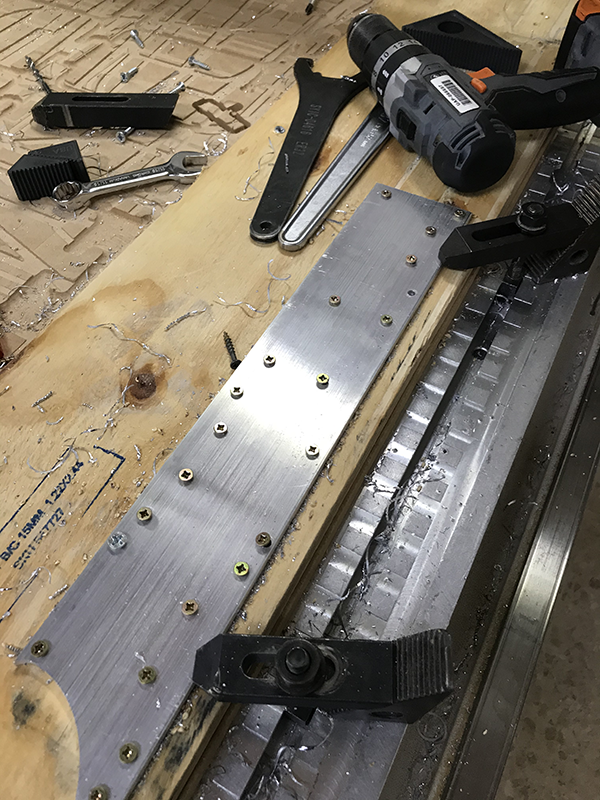
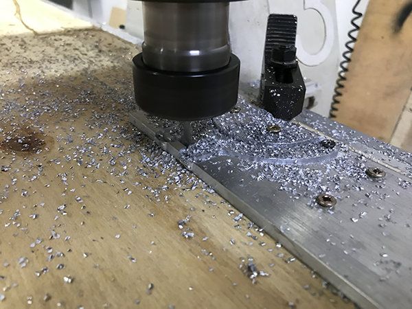
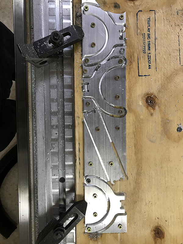
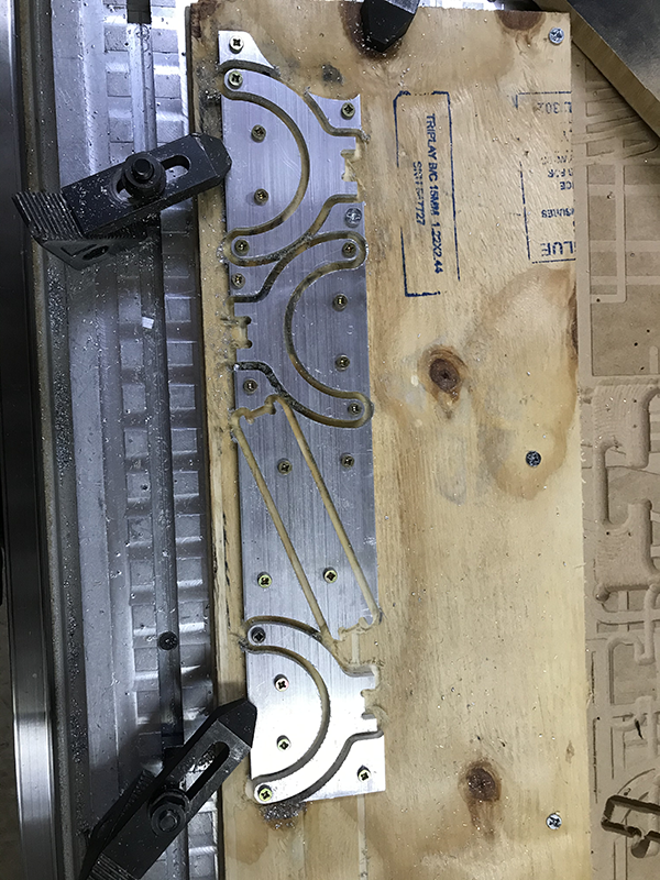
Chassis and construction: CNC MILLING
The plunger assembly needs what I call a chassis that transmits force from the motor to the plunger. I made it out of aluminium. More on this phase can be found on week 7

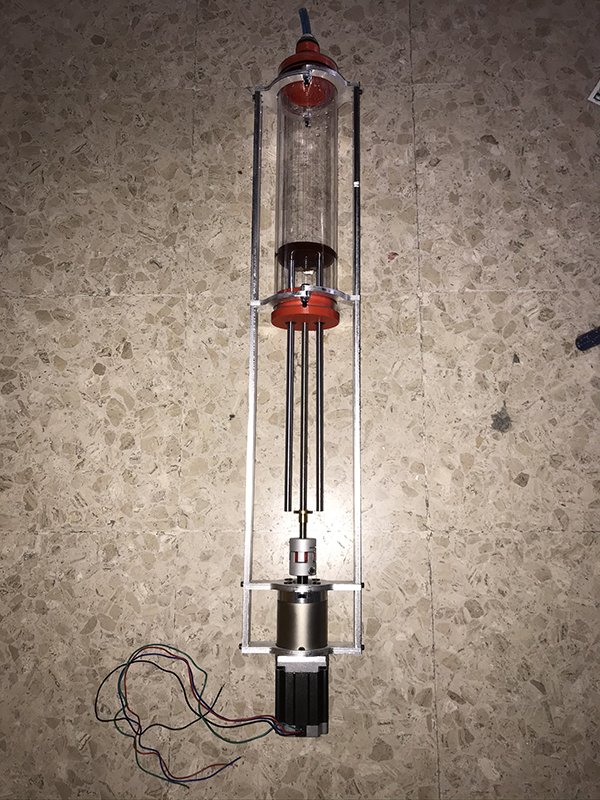
This is the final assembly with the tube and some of the final parts.
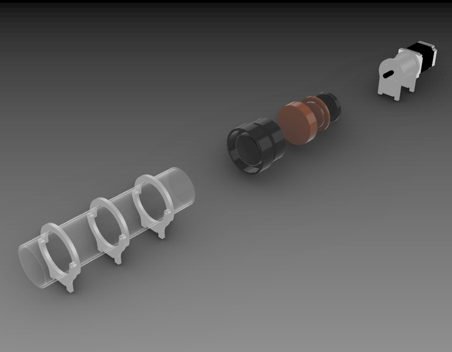
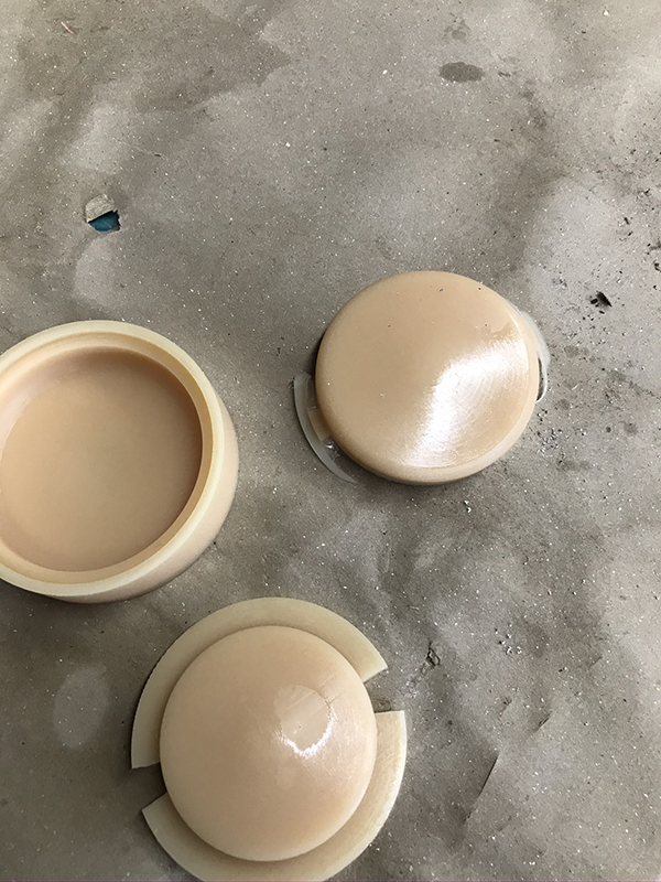
Plastic plunger assembly: MOLDING AND CASTING
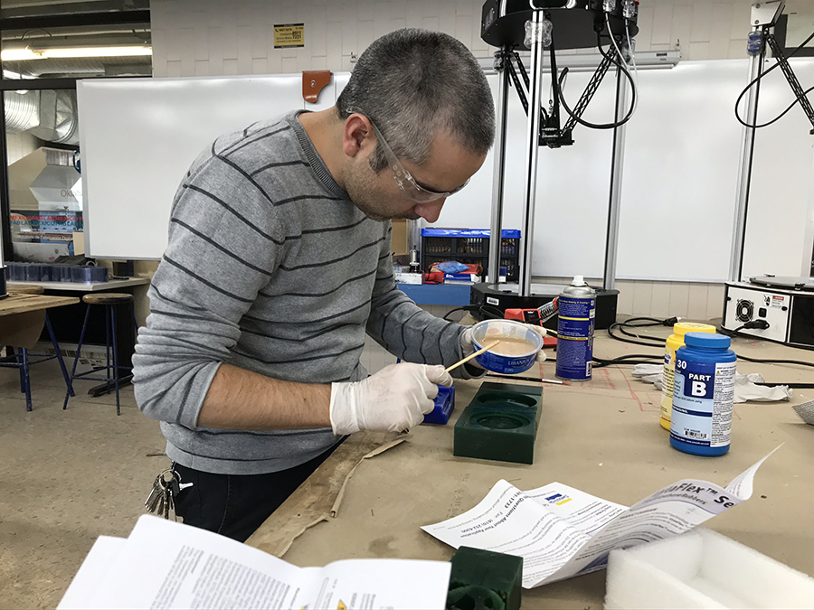
Silicone Plunger Head by Molding and Casting.
I made the sillicone plunger cap out of silicone to provide a better seal on the tube. Here are some images of the process. More information can be found on the molding and casting page.
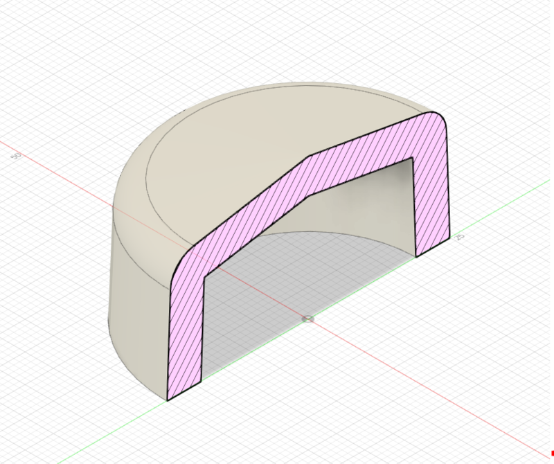
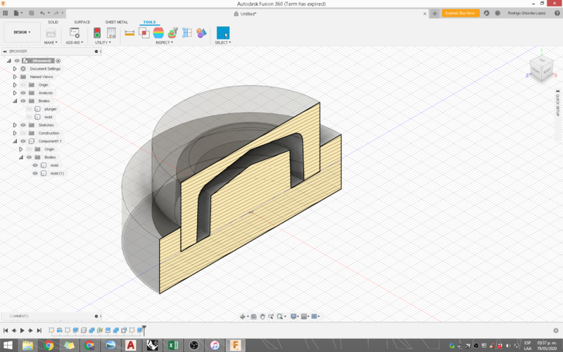
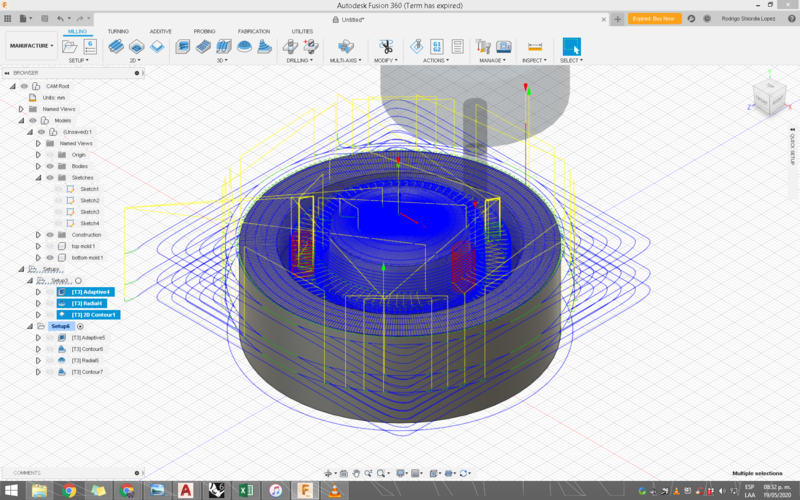
First I needed to make the mold out of machinable wax on the Modela MDX40.
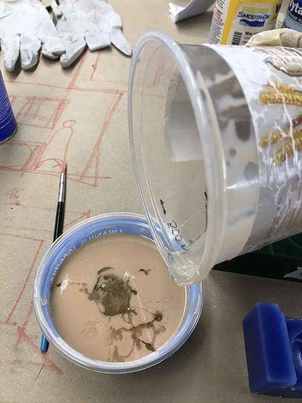
The plunger is cast out of vytaflex40.


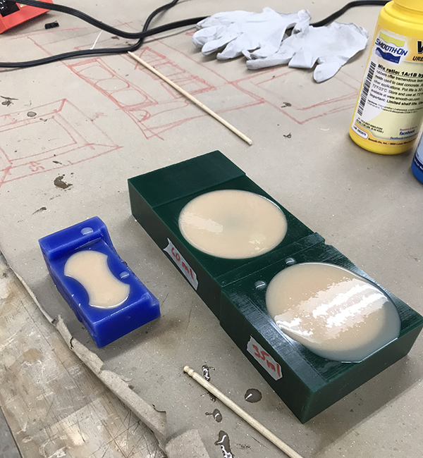
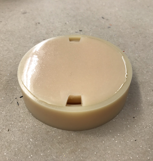
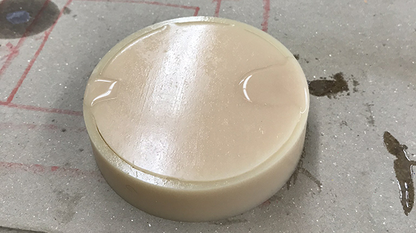
These are the final parts.
Tube cap and new extruder design: 3D PRINTING
I made the tube cap and a new extruder design with 3d printing.
This is the 3d printed cap:
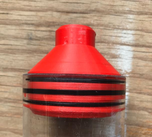
After realizing that the pressure would move it from the tube I had to make a new one, that had some insert nuts.
This new design mas better mounted on the tube.
Extruder assembly design
I did a lot of research for finding the correct parts that could be sourced cheaply and locally so the design was heavily influenced by motor sizes. gears and pieces will be 3d printedd and I'll also have an aluminium chassis. This is one of the first sketches:
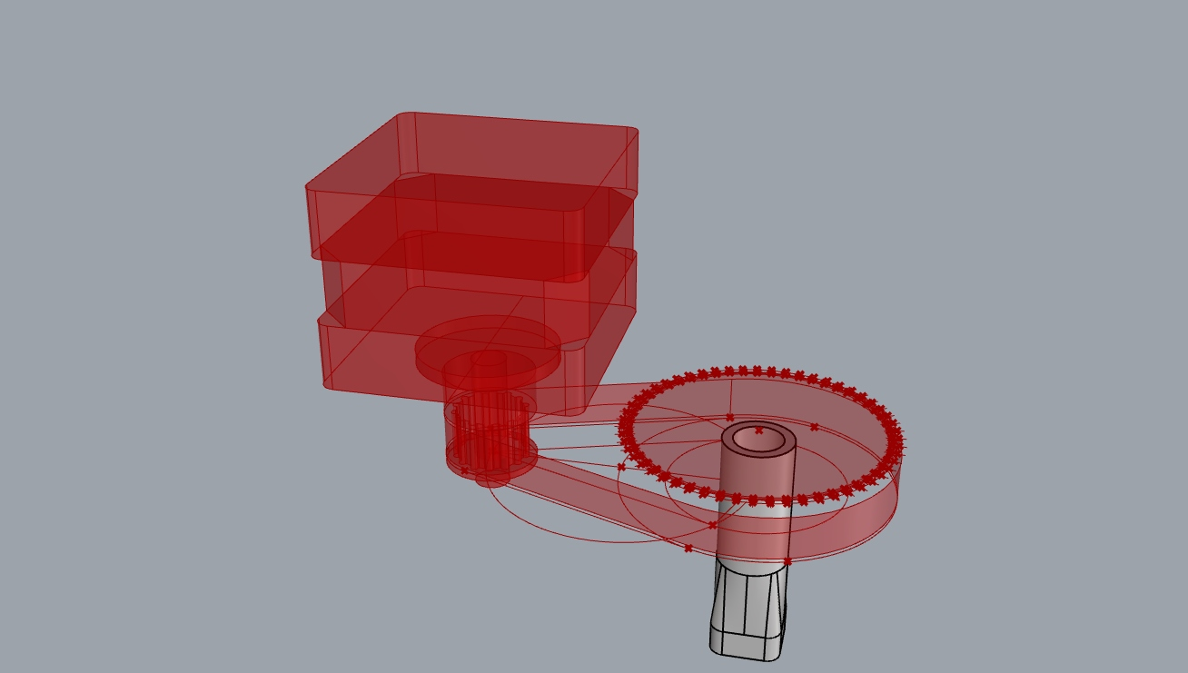
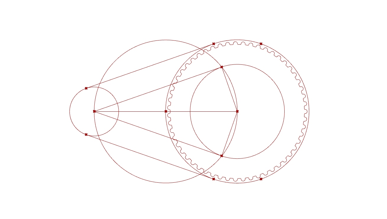
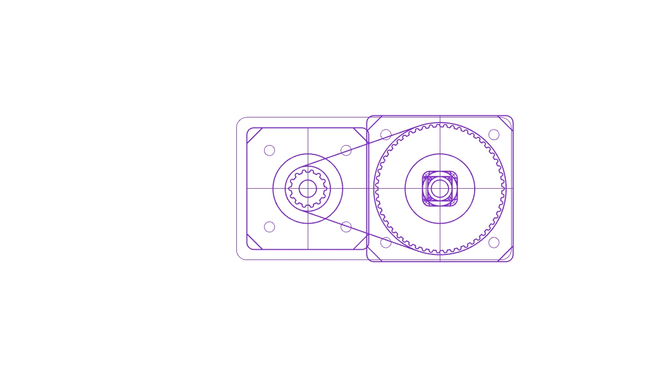
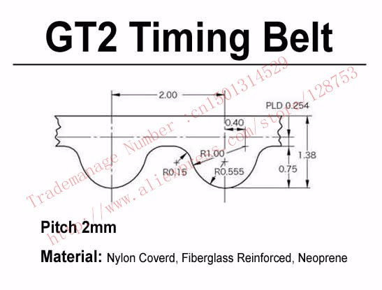
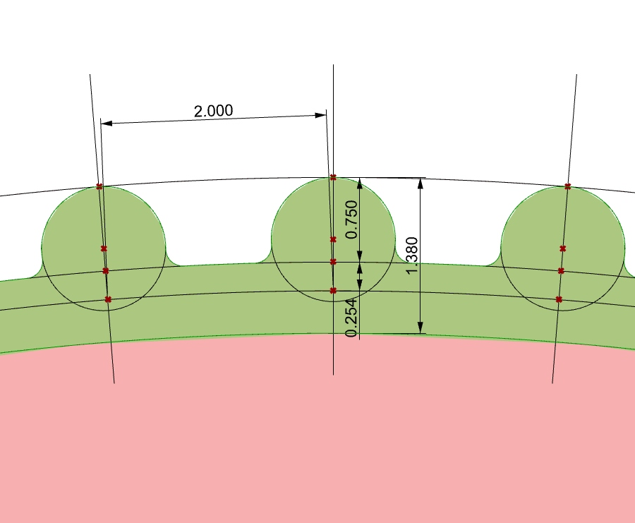
I had to make a paramteric model in order to create the toothed pulleys for the belt I was able to source. I have the spec for the GT2 timing belt, and made a grasshopper file to make the pitch for the tooths exactly identical depending on the belt length and the available space on the design. Here is some of that work:
License
I have decided to use a copyright attribution license. My project could use patents, however, I have not the resources to enforce patents, therefore, the license that most goes with my intentions is fab license:
                      (c) Rodrigo Shiordia 2020

                      This work may be reproduced, modified, distributed, performed, and displayed for any purpose, but must acknowledge "FABCLAYCRAFTER".
                      Copyright is retained and must be preserved.
                      The work is provided as is; no warranty is provided, and users accept all liability.