General objective (group assignment):
- Group assignment:
-
- Send a message between two projects
- Individual assignment:
-
- design, build, and connect wired or wireless node(s) with network or bus addresses
Development
I2C is the same aas IIC which stands for Inter Integrated Circuit, it works with two wires and sends bits one at a time between a master device and a receiver device. Communication can be two way, but both master and slave devices have to have a way of knowing when to transmit. The devices are connected using two wires:
SDA >>>> stands for "serial data line" whcich transmits the bytes of your message, one bit at a time between frame bits and with start and stop condition bits. The devices pull it low to write the bits.
SCL >>>> stands for "serial clock line" which is constantly alternating between high and low voltage, at a constant speed therefore the devices always know when to expect a bit.
These two lines must always have pullup resistors, so that when they are idle, they are HIGH meaning that they are pulled to a 5V voltage.
Multiple devices can be connected to these two lines as long as at the end they have the pull up resistors. In order to have multiple devices, all of the devices must have an address. This address must be a 7-bit address number which means that the limit is 127 device addresses.
Arduino has a special library called Wire.h that works with the SAMD11C. We decided to connect several of our boards together in a network, and have them comunicate between them. On the SAMD11C the pins for SDA and SCL are pins PA14 and PA15.
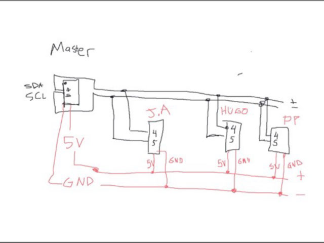
We connected Hugo’s, José’s and Rodrigo’s Boards in a bus using a breadboard. This is the basic diagram:
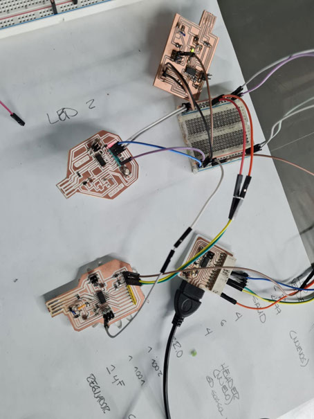
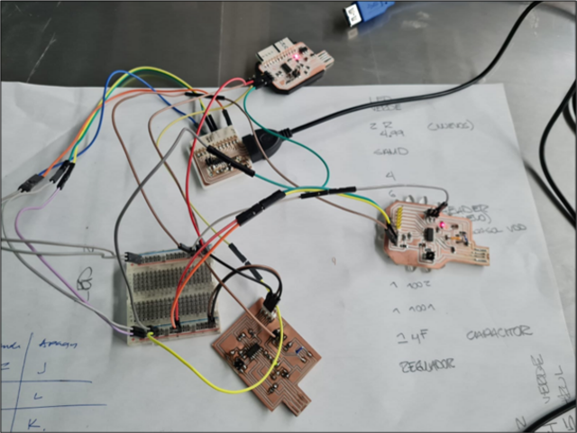
This a picture of how it was connected.
We used Rodrigo’s board as a sender. Here is the code:
#include <Wire.h>
void setup() {
Serial.begin(115200);
Wire.begin(); // join i2c bus (address optional for master)
pinMode(4, OUTPUT);
}
void loop() {
while (Serial.available()) {
char c = Serial.read();
if (c == 'H') {
Wire.beginTransmission(4);
Wire.write('H');
Wire.endTransmission();
Serial.println("writing to address 4!");
}
else if (c == 'L') {
Wire.beginTransmission(4);
Wire.write('L');
Wire.endTransmission();
Serial.println("writing to address 4!");
}
else if (c == 'G') {
Wire.beginTransmission(2);
Wire.write('G');
Wire.endTransmission();
Serial.println("writing to address 2!");
}
else if (c == 'K') {
Wire.beginTransmission(2);
Wire.write('K');
Wire.endTransmission();
Serial.println("writing to address 2!");
}
else if (c == 'F') {
Wire.beginTransmission(3);
Wire.write('F');
Wire.endTransmission();
Serial.println("writing to address 3!");
}
else if (c == 'J') {
Wire.beginTransmission(3);
Wire.write('J');
Wire.endTransmission();
Serial.println("writing to address 3!");
}
else if (c == 'Q') {
digitalWrite(4,HIGH);
delay(1000);
digitalWrite(4,LOW);
Serial.println("writing to LOCAL!");
}
}
}
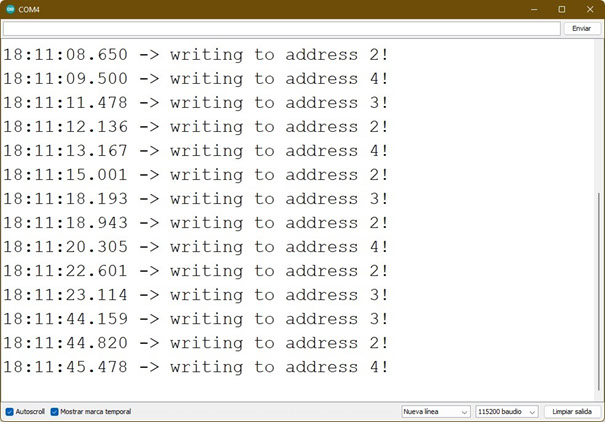
Basically this code opens the I2C bus and also connects to the computer using serial monitor. Every time we send a certain message to the master board, this boards sends another message to the bus on a specific address. We used addresses 2,3,and 4. Basically we came up with six letters to serve as commands.
“F” turns on address 3
“J” turns off address 3
“G” turns off address 2
“K” turns off address 2
“H” turns on address 4
“L” turns off address 4
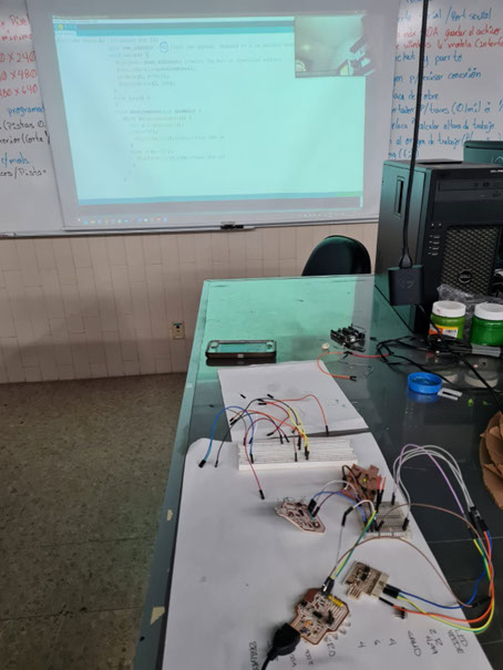
Here is a video of the whole system in operation.
On the receiver boards, we uploaded the code, carefully checking that each one has a unique address. We paired each address with the letters.
#include <Wire.h> //library for I2C
byte own_address = 2; //set own adress, changed to 2 in another board.
void setup() {
Wire.begin(own_address); //enter the bus on specified address
Wire.onReceive(receiveEvent);
pinMode(2, OUTPUT);
digitalWrite(2, LOW);
}
void loop() {
}
void receiveEvent(int howMany) {
while (Wire.available()) {
char c = Wire.read();
if(c=='G'){
digitalWrite(2,HIGH);//turn LED on
}
else if(c=='K'){
digitalWrite(2,LOW);//turn LED off
}
}
}
In order to show that everything works, right now we have an LED turning on and off.