Fab Academy 2020
14. Networking and Communications
14. Networking and Communications
Group assignment :
So far we had been building boards with a single processor, and this week is on how we can work with and integrating multiple boards (or projects) together and have them communicating (or transmitting data) with one another. In order to accomplish this, each divice is being connected to a common bus (or network) and need to have its own unique ID or addresses.
We have exprience in using UART (Tx, Rx) to send data from the target board to the screen on the PC/notebook. In addition, we been frequetly using SPI (Serial Peripheral
Interface)(MISO, MOSI, SCK) to upload our program code to the target board via our 'fabisp'.
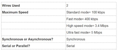
This week, I will be exploring more on I2C communication which is a 'two-wire interface'.
Implementation of I²C Protocol
I2C (Inter-Integrated Circuit), sometimes also pronounced as "I-squared-C" or "I-two-C" or "I-I-C" (written as IIC), combines the best features of SPI and Serial UARTs.
|
What will I design?
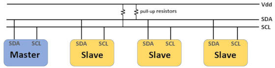
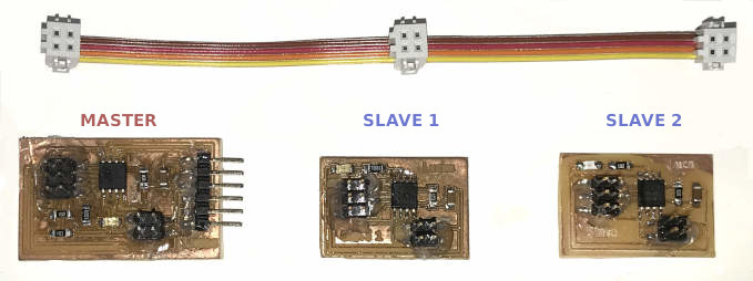
I will be designing and making three boards. One Master and two Slaves (namely Slave 1 and Slave 2). I be using ATTiny45, as in my output device week I having issue with ATTiny44A board running I2C and did not have time to resolve the issue...
How do I connect the boards?
The I2C bus require a MASTER that will initialise and control the clock for the whole I2C bus.
The MASTER board will be connected to the host PC/laptop via a FTDI (usb/serial) adaptor. This allows me to send command to MASTER.
The MASTER, SLAVE 1 and SLAVE 2 are physically connected by an I2C ribbon cable which represent the I2C bus.
The I2C ribbon cable consist of four wires (SDA, SCL, VCC and GND).
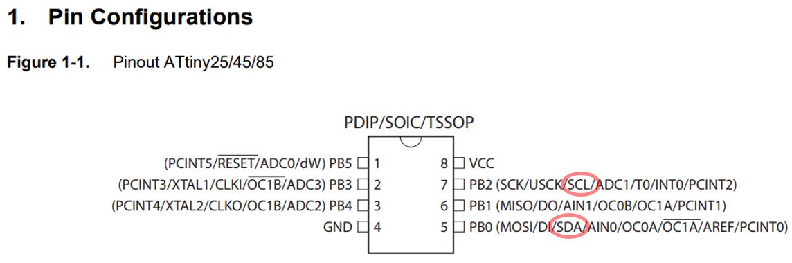
I am using ATTiny45 which is pin 5 (PB0) for SDA pin and pin7 (PB2) for SCL pin.
| Microcontroller | SDA | SCL |
| Arduino Uno | A4 | A5 |
| ATMega328P | 20 | 21 |
| ATtiny45 | 5 (PB0) | 7 (PB2) |
| ATtiny44A | 7 (PA6) | 9 (PA4) |
What will I test?
1) User send a command (data) from serial monitor on the host PC /laptop to MASTER.
2) MASTER evaluate Command send :
'0' : which refer to the MASTER node, the red LED on the MASTER will blink three times.
'1' : which refer to 'Slave 1', MASTER tells SLAVE 1 to blink led 3 times.
'2' : which refer to 'SLAVE 2', MASTER tells SLAVE 2 to blink led 3 times.
3) The MASTER reply to the User what message the User had typed.
I used a pull-up resistor of 10k ohm for the I2C bus (on the SDA and SCL lines) on the Master board. Only one sets of pull-up resistors is required for the whole I2C bus. Note: If your boards are far away from each other, you might reduce the
resistor value.
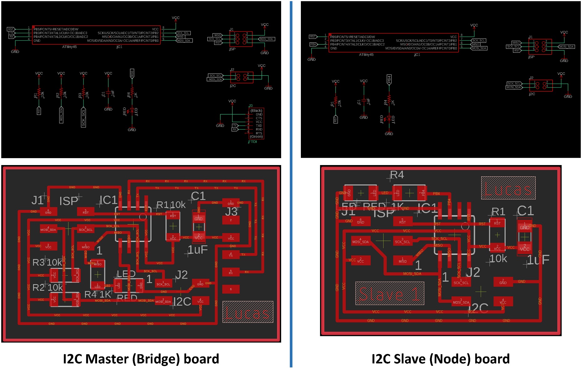
Components require for the Master board :
Components require for two Slaves boards :
Components require for I2C ribbon :
Note : Preferably to use ATTiny85 if your Fab Lab has stock, as the ATTiny85 provide more Program Memory Space if you are writing Arduino codes.
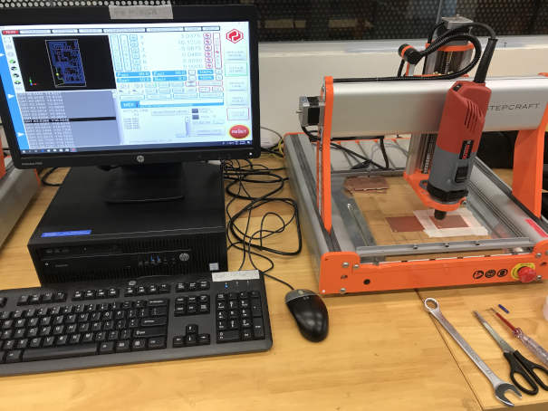
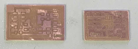
In EAGLE, I rotated the boards to be in vertical orientation, so I can print two boards together in one 2"x3" FR1 copper-clad board. Soldering three boards at one go took some time and effort. Laster I used a glue gun and apply glue to all the
vertical as well as horizontal connector to make sure it is firmly secured in position.
1) Burn the bootloader :
After finished milling the three boards, I uploaded the bootloader using Arduino IDE. Ensure that the clock speed is set to run at 'Internal 8Mhz', if you set to Internal 1Mhz, you will see 'funny' text on the Serial Monitor.
Upload a simple blink LED Arduino sketch to see if the LEDs are working fine.
2) The 'TinyWire' library
As I am using the 'ATTiny' microntroller, I downloaded TinyWireM.h library (for MASTER) and a modified TinyWireS.h library by 'rambo' (for SLAVE)
If you are using the ATMega328P microntroller (or Arduino Uno v3), you can use the built-in 'Wire.h' Arduino library. Take note that the TinyWire library only work on ATTiny MCU as it is built upon 'TWI' which is a sub-set of the implementation of I2C on the ATTiny MCUs family. The Wire.h does not work on ATTiny MCU and the TinyWire libray does not work on ATMega328p MCU. The TinyWire libray also does not work with ATTiny44A MCU, one would need to edit the C source file and change the name as well as the pins assignment first.
3) Coding : Initilaizing I2C
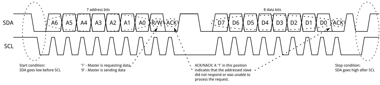
Addressing : There is no need to specify the address for the single MASTER in the I2C bus arrangement. If the board is initialised as a slave, then you would need to specify an address, between 0 to 127 (7-bit address), as its parameter to
uniquely
identifying it on the I2C bus. (Simon Monk, 2019, pp157)
Setup of I2C nodes :
MASTER : TinyWireM.begin();
SLAVE : TinyWireS.begin(x); // where x is the node number
Master sending data :
The 'TinyWireM.beginTransmission(slave address);' function enable the MASTER to start sending data to the designated SLAVE address which is on the I2C bus.
The TinyWireM.send(data) buffer up bytes to send, this function can be called multiple times
TinyWireM.endTransmission() function actually send the bytes in the buffer
4) Upload the code to the Master :
Note : I added in a few more global variable and this quickly filled up the 'dynamic memory' space. So I will have to stop my testing here and not adding any more codes...
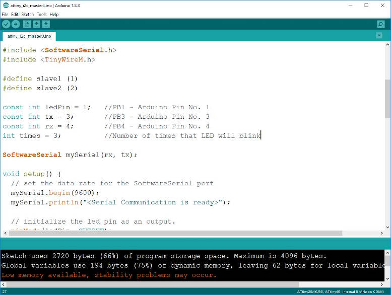
My Code for the MASTER :
/*
  attiny_i2c_master.ino
  by Lucas Lim
  created on 6/5/2020

  Purpose: MASTER receive 'instruction' from PC via serial port (Tx, Rx)
           MASTER reply acknoledge message back to PC
           If instruction is to Slave 1/2, MASTER re-route to addressed
              SLAVE 1/2 via I2C bus
           Instruction :
             '0' MASTER will Blink LED
             '1' SLAVE 1 will blink LED
             '2' SLAVE 2 will blink LED
  NOTE! - It is important to use pullups on the SDA & SCL lines on the I2C bus!

  The work is provided for academic purpose for Fab Academy 2020.
  Users accept all as is, no warranty is provided, no call/email
  from users will get a response. Users accept all liability.
*/

#include <SoftwareSerial.h>
#include <TinyWireM.h>

#define slave1 1
#define slave2 2

const int ledPin = 1;   //PB1 - Arduino Pin No. 1
const int tx = 3;       //PB3 - Arduino Pin No. 3
const int rx = 4;       //PB4 - Arduino Pin No. 4
int times = 3;          //Number of times that LED will blink

SoftwareSerial mySerial(rx, tx);

void setup() {
  // set the data rate for the SoftwareSerial port
  mySerial.begin(9600);
  mySerial.println("< Serial Communication is ready>");

  // initialize the led pin as an output.
  pinMode(ledPin, OUTPUT);

  // join I2C bus as MASTER
  TinyWireM.begin();
}


void process_incoming_command(char cmd)
// Received user command from host PC via Software Serial
{
  switch (cmd)
  {
    case '0':                     // MASTER to blink led
      blink_led(times);
      break;
    case '1':                     // Slave 1 to blink led
      TinyWireM.beginTransmission(slave1);
      TinyWireM.send(times);
      TinyWireM.endTransmission();
      break;
    case '2':                     // Slave 2 to blink led
      TinyWireM.beginTransmission(slave2);
      TinyWireM.send(times);
      TinyWireM.endTransmission();
      break;
  }
}


void blink_led(int times)
{
    while(times--)
    {
        digitalWrite(ledPin, HIGH);
        delay(500);
        digitalWrite(ledPin, LOW);
        delay(500);
    }
}

void loop() {
  // don't read unless there is data, Serial.available() > 0
  if(mySerial.available())
  {
    char cmd = mySerial.read();  //User to type '0' for MASTER, '1' for SLAVE 1 and '2' for SLAVE 2"
    mySerial.print("You typed : ");
    mySerial.println(cmd);
    process_incoming_command(cmd);
  }

  delay(50);   //limit how fast the serial check/update
}
My Code for Slave 1 :
Note : The code for Slave 2 is the same as Slave 1 except the following line at the top :
"#define i2c_slave2 2"
which set the I2C address for Slave 2 board
/*
  attiny_i2c_slave1.ino
  by Lucas Lim
  created on 6/5/2020

  Purpose: Receive data from MASTER via the I2C bus
           Blink the LED

  The work is provided for academic purpose for Fab Academy 2020.
  Users accept all as is, no warranty is provided, no call/email
  from users will get a response. Users accept all liability.
*/

#include <TinyWireS.h>

#define i2c_slave1 1

const int ledPin = 4;       //PB4 - Arduino Pin No. 4
//int times = 0;            //Number of times that LED will blink
byte received = 0;          //Received data(on number of times that LED will blink) from MASTER


void setup()
{
    TinyWireS.begin(i2c_slave1);    // join I2C bus as slave

}


void blink_led(int times)
{
    while(times--)
    {
        digitalWrite(ledPin, HIGH);
        delay(500);
        digitalWrite(ledPin, LOW);
        delay(500);
    }
}


void loop()
{

    if (TinyWireS.available()) {
      received = TinyWireS.receive();
      blink_led(received);
    }
    received = 0;


    // This needs to be here
    TinyWireS_stop_check();
}
Duration : 57 secs
Audio : No
The expectation for this week group assignment is to send a message between any combination of boards, computers and/or mobile devices.
Therefore I going to explore furthur into the posibility of incorporating I2C protocol to my final project or how I can better use of I2C protocol.
I am using two of my fabricated boards, a ATMega328P board (fabricated in output device week) as well as ATTiny45 (fabricated this week). Each board is running it's own process and serving a different function. I have added an ultrasonic sensor and a I2C LCD display module. I came up with the following plan.
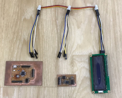
Setup :
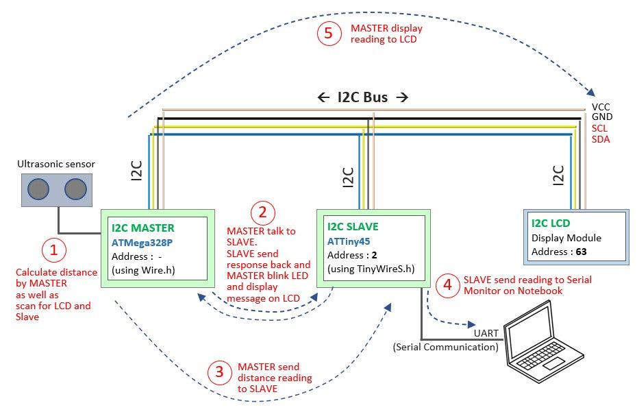
Here I have :
I2C Bus Wiring :
For the wiring, I using back my fabricated i2c ribbbon wire as well as used a number of jumper wires to branch out from I2C ribbon wire to connect to the two boards and LCD. This allows me to easily space the devices out, better cable managemeent and better handling(moving around).
White color jumper wire for VCC,
Black color jumper wire for GND,
Blue color jumper wire for SDA and
Yellow color jumper wire for SCL.
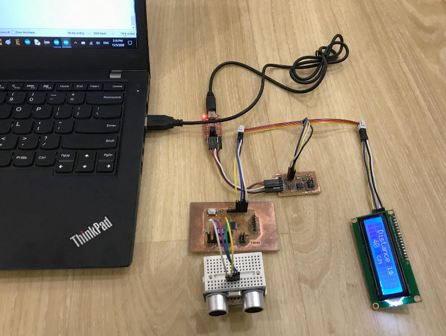
Steps :
1. I layout the boards and I2C LCD module as shown in picture above.
2. I setup the I2C MASTER as well as the I2C address for the Slave with the following codes.
MASTER :
Wire.begin(); // join i2c bus as master, no address is stated
SLAVE :
TinyWireS.begin(i2c_slave); // join i2c network as slave
Note :
I am using the ATMega328P board as the MASTER, as earlier on I found that my ATTiny45 will quickly run out of memory space.
The MASTER generates the clock and has no address. For both boards, I had set to run at 8Mhz Internal Clock just to be sure it will work without any issue.
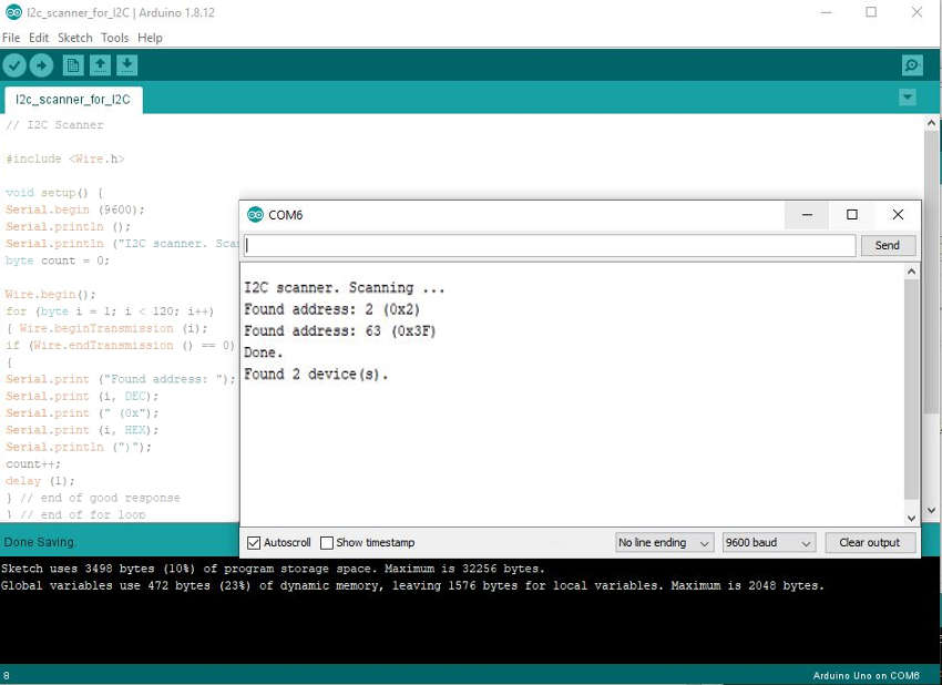
3. I ran my modified I2C scanner code on the MASTER, and is able to detect the I2C Slave node as well as the I2C LCD. This show that the addressing is working ok.
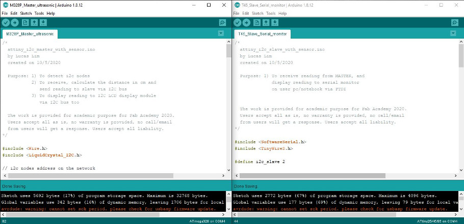
4. I have writen my code using Arduino IDE, with two seperate windows open side-by-side displaying onto my 28" LCD monitor. Testing and programming the board one at a time, one for MASTER With the ATMega328P, the other for the Slave with ATTiny45.
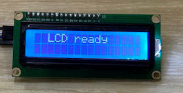
5. Scanning for LCD : The I2C MASTER board when powered up, will first scan for the I2C LCD and if found, it will display "LCD Ready" on the LCD. This show that LCD is working ok.
#define i2c_lcd 63
...
Wire.beginTransmission (i2c_lcd);
if (Wire.endTransmission() == 0) { // check if lcd is available
lcd.setCursor(2, 0);
lcd.print("LCD ready");
...
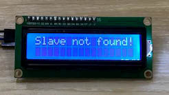
6. Scanning for Slave : The MASTER will then scan for the I2C Slave and if found, it will display "Slave detected" on the LCD display, otherwise, it will show "Slave is not found!".
#define i2c_slave 2
...
Wire.beginTransmission (i2c_slave);
// if return = 2 : received NACK on transmit of address
// if return = 4 : other error
if (Wire.endTransmission() ==2 || Wire.endTransmission() ==4) { // check if slave is available
lcd.setCursor(1, 0);
lcd.print("Slave detected");
...
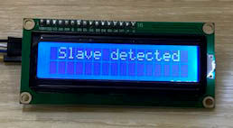
If one of the wires is loose or not connected to the Slave board, Slave will not be able to response. This is to check the connection.
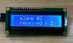
7. After detecting the Slave node, the MASTER will talk to the Slave and request data from the Slave. The Slave will send a message ("2") back to MASTER. MASTER will verify the message, if matches the expected response, MASTER will blink the LED 3 times on the MASTER board and display the message received on the LCD.
MASTER :
Wire.requestFrom(i2c_slave, 1);
while(Wire.available())
{
c1 = Wire.read(); // receive a byte from Slave # 2
}
lcd.print("slave # ");
lcd.print(i2c_slave);
lcd.print("received : ");
lcd.print(int(c1));
if (c1 == i2c_slave) {
delay(2000); // to facilitate the recording of video, this can be deleted
blink_led(3); // blink led to indicate receive of acknowledgement (or data) from Slave
}
delay(2000);
lcd.clear();
SLAVE :
TinyWireS.onRequest(requestEvent);; // listen to request from master node
...
// Gets call when receive a request from MASTER and response with a message
void requestEvent() {
TinyWireS.send(2);
}
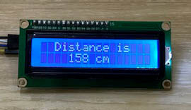
8. The MASTER is able to calculate and display the reading to the LCD.
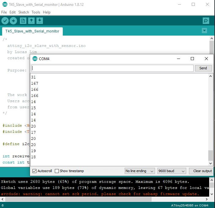
9. Slave is able to print out distance reading to serial monitor on the notebook via a FTDI adaptor. With this, an application can be added on later to do data visualisation or provide a GUI interface.
My Code for the MASTER connected with the sensor :
/*
  M328P_Master_ultrasonic_and_i2c_scanner.ino
  by Lucas Lim
  created on 10/5/2020

  Purpose: 1) To detect i2c nodes
           2) To receive, calculate the distance in cm and
              send reading to slave via I2C bus
           3) To display reading to I2C LCD display module
              via I2C bus too

  The work is provided for academic purpose for Fab Academy 2020.
  Users accept all as is, no warranty is provided, no call/email
  from users will get a response. Users accept all liability.
*/

#include <Wire.h>
#include <LiquidCrystal_I2C.h>

// i2c nodes address on the network
#define i2c_lcd 63
#define i2c_slave 2

LiquidCrystal_I2C lcd(i2c_lcd, 16, 2);     // set the LCD address, for a 16 chars by 2 rows display

int trigPin = 7;             // Trigger (PD7 - arduino pin no. 7)
int echoPin = 8;             // Echo    (PB5 - arduino pin no. 8)
long duration, cm;
const int ledPin = 2;        // PD2 - Arduino pin no. 2
byte c1 = 0;                 // for requestFrom()

void blink_led(int times)
{
    while(times--) {
        digitalWrite(ledPin, HIGH);
        delay(350);
        digitalWrite(ledPin, LOW);
        delay(350);
    }
}


void i2c_scan_nodes() {
  // scan for LCD
  Wire.beginTransmission (i2c_lcd);
  if (Wire.endTransmission() == 0) {
    lcd.setCursor(2, 0);
    lcd.print("LCD ready");
    delay(3000);
    lcd.clear();
  }
  Wire.endTransmission();

  // scan for I2C Slave
  Wire.beginTransmission (i2c_slave);
  if (Wire.endTransmission() == 0) {
    lcd.setCursor(1, 0);
    lcd.print("Slave detected");
    delay(3000);
    lcd.clear();
  }
  // if return = 2 : received NACK on transmit of address
  // if return = 4 : other error
  else if (Wire.endTransmission() ==2 || Wire.endTransmission() ==4) {
    lcd.setCursor(0, 0);
    lcd.print("Slave not found!");
    delay(3000);
    lcd.clear();
  }
  Wire.endTransmission();


  Wire.requestFrom(i2c_slave, 1);
  while(Wire.available())
  {
    c1 = Wire.read();        // receive a byte from Slave # 2
  }

  lcd.setCursor(2, 0);
  lcd.print("slave # ");
  lcd.setCursor(9, 0);
  lcd.print(i2c_slave);
  lcd.setCursor(2, 1);
  lcd.print("received : ");
  lcd.setCursor(13, 1);
  lcd.print(int(c1));
  if (c1 == i2c_slave) {
    delay(2000);              // to facilitate the recording of video, this can be deleted
    blink_led(3);             // blink led to indicate receive of acknowledgement (or data) from Slave
  }
  delay(2000);
  lcd.clear();
}


void sensor() {
  // The sensor is triggered by a HIGH pulse of 10 or more microseconds.
  // Give a short LOW pulse beforehand to ensure a clean HIGH pulse:
  digitalWrite(trigPin, LOW);
  delayMicroseconds(5);
  digitalWrite(trigPin, HIGH);
  delayMicroseconds(10);
  digitalWrite(trigPin, LOW);

  // Read the signal from the sensor: a HIGH pulse whose
  // duration is the time (in microseconds) from the sending
  // of the ping to the reception of its echo off of an object.
  pinMode(echoPin, INPUT);
  duration = pulseIn(echoPin, HIGH);

  // Convert the time into a distance
  cm = duration *0.034/2;
}


// Display ultrasonic sensor reading to LCD
void lcd_display(int cm)
{
  lcd.setCursor(4,1);
  lcd.print("    ");      // clear the previous reading

  lcd.setCursor(4,1);
  lcd.print(cm);
}


// send reading to Slave # 2
void send_reading(int msg)
{
  Wire.beginTransmission(i2c_slave);
  Wire.write(msg);
  Wire.endTransmission();
}


void setup() {
  delay(2000);   // to facilitate the recording of video, this can be deleted

  // join i2c bus as master, no address is require
  Wire.begin();

  // Initialize the LCD, must be called in order to initialize I2C communication
  // lcd.begin();           // LCD library for ATTiny45
  lcd.init();         // LCD library from Arduino

  // Turn on the backlight
  lcd.backlight();

  // blink LED (this must be setup calling i2c_scan_nodes)
  pinMode(ledPin, OUTPUT);

  // scan for presence of I2C LCD and Slave node
  i2c_scan_nodes();

  // display static text info for distance reading
  // these text doesn't change on LCD
  lcd.setCursor(2, 0);
  lcd.print("Distance is");
  lcd.setCursor(8,1);
  lcd.print("cm");

  // setup ultrasonic sensor pins
  pinMode(trigPin, OUTPUT);
  pinMode(echoPin, INPUT);
}


void loop() {
  // activate sensor and receive reading data
  sensor();

  //send reading to SLAVE # 2
  send_reading(cm);

  lcd_display(cm);

  // slow down for easy reading
  delay(800);
}
My Code for the SLAVE connected to the PC/notebook:
/*
  T45_Slave_with_Serial_monitor.ino
  by Lucas Lim
  created on 10/5/2020

  Purpose: 1) To receive reading from MASTER, and
              display reading to serial monitor
              on user pc/notebook via FTDI


  The work is provided for academic purpose for Fab Academy 2020.
  Users accept all as is, no warranty is provided, no call/email
  from users will get a response. Users accept all liability.
*/

#include <SoftwareSerial.h>
#include <TinyWireS.h>

#define i2c_slave 2

int received = 0;           // receive cm reading
const int tx = 3;           // PB3 - Arduino pin no. 3
const int rx = 4;           // PB4 - Arduino pin no. 4
const int ledPin = 1;       // PB1 - Arduino pin no. 1

SoftwareSerial mySerial(rx, tx);


// Gets call when receive a request from MASTER and response with a message
void requestEvent() {
  TinyWireS.send(2);
}


void receiveEvent() {
  received = TinyWireS.receive();
}


void blink_led(int times)
{
    while(times--)
    {
        digitalWrite(ledPin, HIGH);
        delay(500);
        digitalWrite(ledPin, LOW);
        delay(500);
    }
}


// display reading to serial monitor
void display_reading()
{
    //if (TinyWireS.available()) {
      received = TinyWireS.receive();
      mySerial.println(received);
    //}
}


void setup() {
  TinyWireS.begin(i2c_slave);            // join i2c network as slave

  mySerial.begin(9600);                  // start serial for output

  TinyWireS.onRequest(requestEvent);     // listen to request from master node
  TinyWireS.onReceive(receiveEvent);     // function to be called when a slave device receives a transmission from a master

  pinMode(ledPin, OUTPUT);
}


void loop() {
  //display reading to serial monitor
  mySerial.println(received);

  // This needs to be here, Detects a stop sending command.
  TinyWireS_stop_check();
}
Duration : 41 secs
No Audio
Speed increased by 20%
Serial Commincation :
I learn that there are basically three type of communication protocols available UART, SPI, and I2C (or TWI in ATTiny44/45 chips). UART is the serial communication with the
computer using Tx and Rx pins, and I2C using SDA and SCL pins. Each of these differ in their implementation, but they also can co-exist together.
Delay faced :
Previously I just mill one board at a time. But this time round, I am milling three boards at one go with the board designs arranged nicely next to each other... and didn't realise the tip of
my v-bit was worn out half-way through the milling. During the etching, it is good that I periodically check on the traces to see if it look ok.
Programming : I2C :
I was using the original TinyWireS library, but having issue with RequestEvent() function working together with Serial Communication. Slave is not able to response to MASTER and no data was send. Moreover, the reading did not printed out on the screen. Later I changed the TinyWireS library to a modified version from "rambo" and it work fine.
Note on I2C Programming :
1. Try to set the same clock speed on all the I2C nodes, even thought the MASTER controls the clock. So I set the nodes to all use 8Mhz Internal Clock.
2. Don't put a Delay(); inside any I2C function or during I2C communication. It might have impact on the I2C communication process and 'jam' up the bus...
3. Try not to put a Seial.print() inside any I2C function or during I2C communication for the similiar reason above.
4. The memory space of ATTiny45 is quite limited. This restrict the number of variable as well as coding you can write.
Multiple projects :
Integrating multiple projects into the same I2C bus took me a lot of time, as I had to move to-and-fro to test and program the MASTER board and then the SLAVE board and back again...
Here I learned that you can have smaller board(s) to handle the sensor or simple serial communication or other simple role/function, while a board with more memory space can handle more complex operation, calculation, or tother heavy processing like using Array, etc. This is sort-of like a 'distributed' model where the workload can be distributed out.
I can use my ATMega328P board to do all these, but the wiring will be messy or untidy. I2C might also be seen a good way to do cable management.
Having the reading output to serial, I can link up with an GUI application like python.
Design :
- I2C Master Schemetic
- I2C Master Board
- I2C Slave Schemetic
- I2C Slave Board
Individual Assignment :
- attiny_i2c_master.ino
- attiny_i2c_slave1.ino
- attiny_i2c_slave2.ino
Multiple projects with ultrasonic sensor :
- M328P_Master_ultrasonic_and_i2c_scanner.ino
- T45_Slave_with_Serial_monitor.ino
- Wikipedia : I²C
- Sparkfun : I²C
- Circuit Basic : I²C
- ATTiny I2C slave
- Simon Monk, 2019, Programming Arduino Next Steps : Going Futhur with sketches, Second Edition, McGraw-Hill Education, USA, pp 153 - 159 on I2C
- More info on the function of Wire.h on Arduino website
- More info on the function of TinyWireM.h on GitHub