Week 11&12 - Mechanical Design, Machine Design
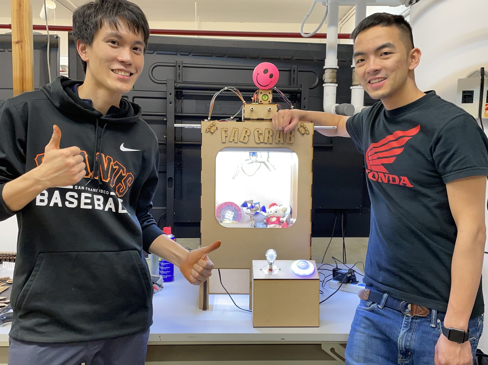
FABGRAB: Grab whatever we Fab!
Group Assignment
- Design a machine that includes mechanism + actuation + automation
- Build the mechanical parts and operate it manually.
- Actuate and automate your machine.
Intro and Inspiration
One night after Fablab, we decided to relax a bit and play with claw machine games nearby the lab. Frustrated that all the machines were designed to be “scammy” (i.e. purposely drop your prize before it reaches the hole), we thought we could build a better one that “doesn’t suck”.
We had most of what we needed to make one in the lab, and would program it so that the claw algorithm would just nicely carry your prize over to the hole and THEN open the claw.
Project Responsibilities
We divided the roles for the project as following:
Hanson
- Mechanical subsystem
- Structural design and production
- X-axis and Y-axis rails
- Claw linkage mechanism
- Z-axis spindle
- Accoutrements
Zack
- Electronics subsystem
- PCB design and production
- Programming
- Control board integration and wiring
- Power supply
- Lighting
Electronics Design
Spiral 0 test with Arduino and breadboard first. Familiarize with stepper motor and servo motor control and programming process.
Inputs - 8 buttons, total pins = 8 Outputs - 3 stepper motors, 1 servo, total pins = 7
AVR128DB32 has 32 pins
Drew schematic and PCB layout in KiCad.
Gap between AVR128 pins is 0.3mm but the smallest end mill we have is 0.4mm. Had to “trick” fab modules that we were using a 0.3mm end mill. Accounted for extra kerf by making traces thicker.
PNG export 500 dpi on first try. Some edges were not good (perhaps end mill starting to get old)
PNG export 1000 dpi for second try, toolpath lines looked straigter in fab modules, particularly around the AVR128 footprint.
Result was much better
Forgot to add in servo in the PCB design, had to solder a wire directly onto a tiny pin that was capable of PWM in the bottom right of the MCU.
Mechanical Design
Tested with small scale first using laser cut model. Including machine structure, rail system, claw design.
Try to edit existing files in the beginning, but fail to adjust kerf and other user parameter in imported Fusion360 file. So doing most of work myself instead.
See more: Heng Chang’s site
Reference carb image MeArm claw design Laser cut rail idea
3D Model
Code Snippet
void loop() {
  // read button states
  buttonStateXn = digitalRead(buttonXn);
  buttonStateXp = digitalRead(buttonXp);
  buttonStateYn = digitalRead(buttonYn);
  buttonStateYp = digitalRead(buttonYp);
  buttonStateZ = digitalRead(buttonZ);
  limitSwitchStateX = digitalRead(limitSwitchX);
  limitSwitchStateY = digitalRead(limitSwitchY);
  limitSwitchStateZ = digitalRead(limitSwitchZ);

  // move crane left on joystick left
  if (buttonStateXn == LOW) {
    if (limitSwitchStateX == HIGH) {
      goLeft();
      limitSwitchStateX = digitalRead(limitSwitchX);
    }
  }

  // ... etc for other directions

  // activate grab algorithm on z button pressed
  if (buttonStateZ == LOW) {
    // open claw (should be open already, but run just in case)
    claw.write(clawServoOpen);

    // drop claw z for set number of steps
    for(int x = 0; x < 1000 ; x++) {
      digitalWrite(dirPinZ,HIGH);
      stepForward(stepPinZ);
    }
    delay(2000);

    // close claw
    claw.write(clawServoClosed);
    delay(1000);

    // move claw up until limit switch z hit
    while (limitSwitchStateZ == HIGH) {
      digitalWrite(dirPinZ,LOW);
      stepForward(stepPinZ);
      limitSwitchStateZ = digitalRead(limitSwitchZ);
    }

    // move claw off limit switch z a bit
    for(int x = 0; x < 100 ; x++) {
      digitalWrite(dirPinZ,HIGH);
      stepForward(stepPinZ);
    }
    delay(1000);
    goHome();
    claw.write(clawServoOpen);
  }
}
Debugging
Claw stopped working when moved to a permanent power supply (AC wall adapters with DC end cut and stripped). There is power and holding strength in the servo but the position is completely off and wobbles like crazy sometimes. Suspected problem lies in the PWM signal being messed up somewhere in the wiring or circuit board. Didn’t have time to debug this before project delivery deadline.
Conclusion
It was a busy two weeks! And we pulled an all-nighter on the last night to finish it. Quite stressful, but we learned a lot about machine design and electronic controls and had great satisfaction finishing the project.