Week 13 - Input Devices
Group Assignment
- Probe an input device’s analog levels and digital signals
Step Response
In this week’s assignment we both made step response input devices. These have both digital and analog attributes.
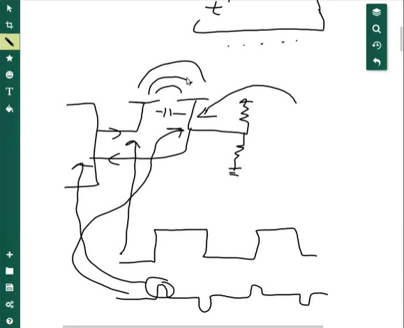
In lecture, we learned from Neil how it works. A Tx electrode creates step wave functions. A Rx electrode in between two large resistors (1M ohm) is placed next to it. There is a capacitance effect and an electric field is generated in between the electrodes. The Rx pin (analog input to MCU) will have a tiny blip at the beginning and end of the Tx pin’s step. Change in voltage creates this electric field response. When something enters the electric field like a hand, it will interact with the field and this results in a slightly different blip read on the Rx analog input.
The Tx is a step or wave function, much like a digital signal, and the Rx is an analog signal/level that responds to it and is read by the MCU.
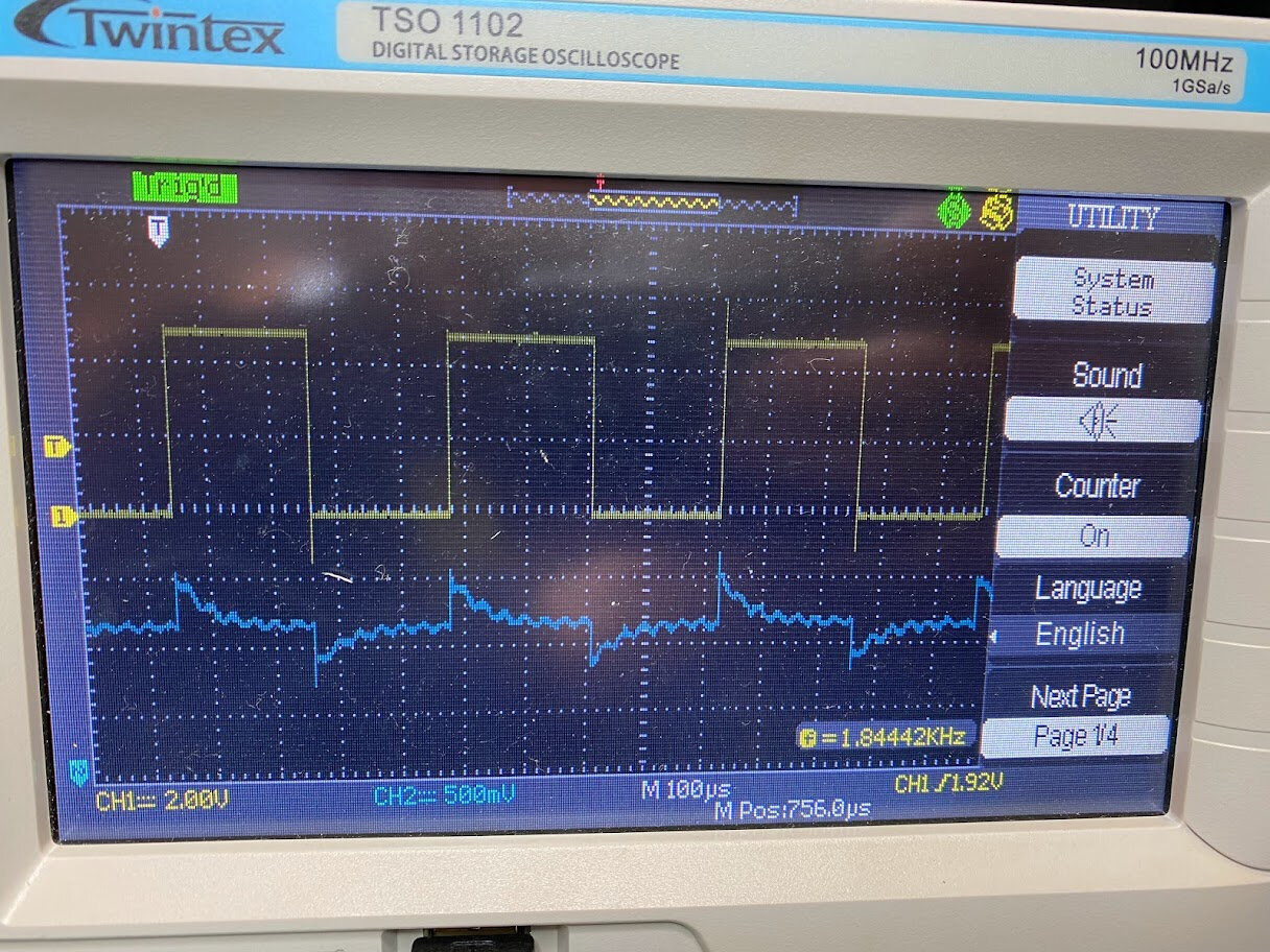
We reproduced Neil’s diagram on the oscilloscope using Hanson’s step response setup. Zack’s ESP32 version was very buggy.
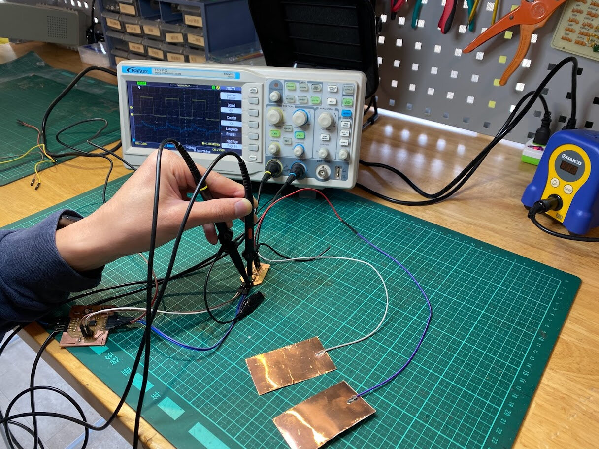
The setup.
Interacting with the step response input video
Update:
Neil said can’t probe step response like this because the oscilloscope becomes part of the step response. He mentioned using active probes.