Week 10 - Output Devices
Group Assignment
- Measure the power consumption of an output device
Intro
We measured two output devices for this assignment, one big and one small. We first measured how much power an LED consumes on one of our button blick hello world boards. Then we measured the power consumption of various DC motors we had in the lab.
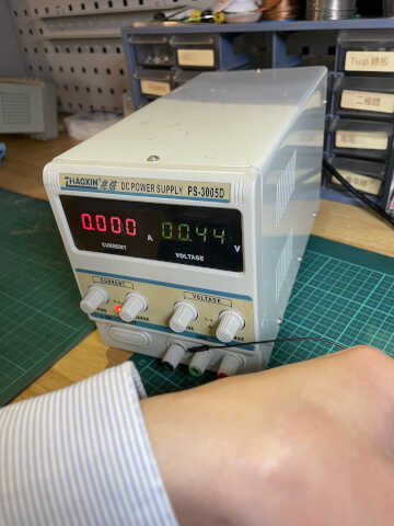
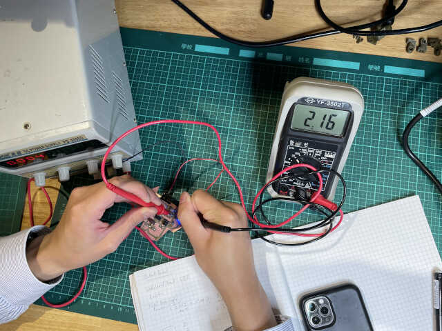
We used 2 tools to do this. First is multimeter, second one is DC Power Supply Machine to adjust voltage & current.
Measuring LED chip power consumption
We use the Machine to provide 5V and GND, but the current flow too small and hard to estimate with it. With 2 equations we can measure the actual power consumption of LED by multimeter.
- V = IR
- P = IV
Since the current went through resistor and LED is the same, we can first estimate V(resistor) and divided by R, and get the I(current).
And then we estimate V(LED) times I(current) and get P(LED) = 12.1 mW!
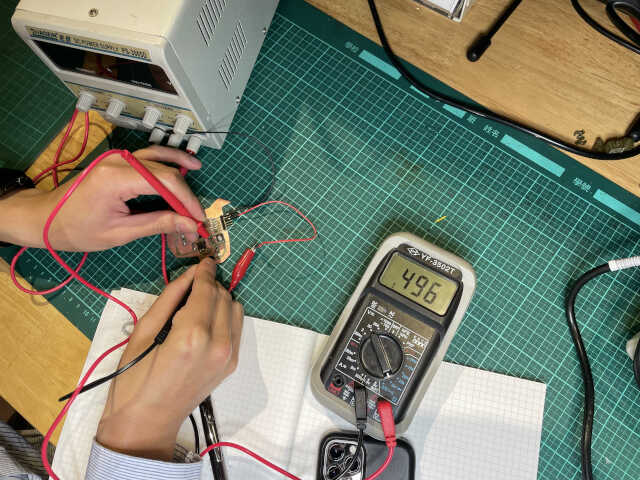
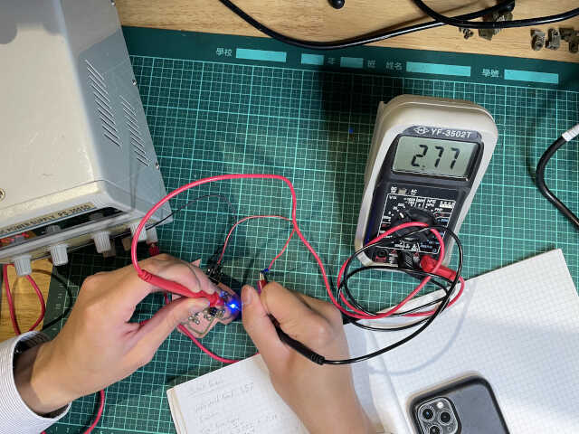
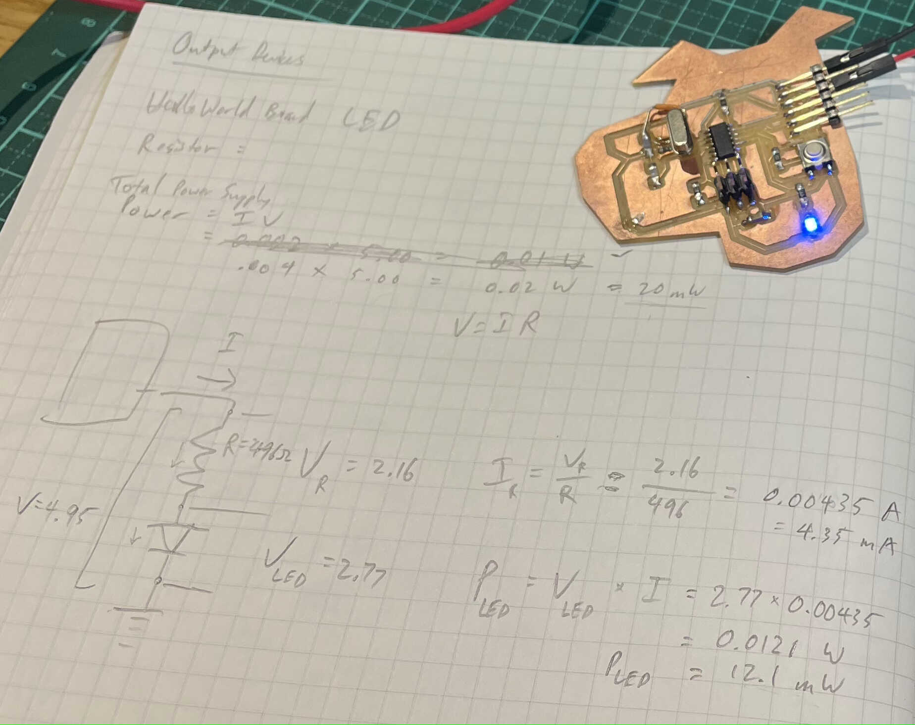
It turns out that V(LED+resistor) = 4.93, almost equal to 5 but not exactly. WHich may be the microcontroller comsumption or some loss.
Measuring DC motor power consumption
First we found some DC motors and read the voltage limitation of them.
Steps for using machine:
- Turn all button anti-clockwise to the end (zero).
- Connect VCC/GND wires to motor, and press “power” button.
- Turn current “fine” (small adjust) clockwise a little bit to give some initlal current.
- Turn voltage “coarse” (big adjust) clockwise till close to the voltage limitation, and then use voltage “fine” to reach limitation.
During the adjust, you may find numbers become fixed without changing, and a red light (c.c.) or green light (c.v.) light up. Which means current (c.c.) or voltage (c.v.) has become a limit factor. So turn the one which lights up until light off, and change to adjust another.
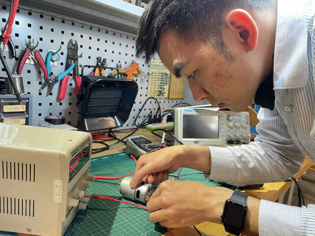
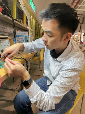
Also some photos while Yoyo was trying to peel the wire. (Since we don’t have enough “banana clips” in Fablab, can only use other wires connect to machine.)