Week 3 - Computer Controlled Cutting
This week we were tasked with determining the characteristics of our Fab Lab’s laser cutter. The properties to characterize were:
- Focus
- Power
- Speed
- Rate
- Kerf
- Joint clearances and types
Principles of laser cutting
Laser cutters are computer-controlled machines that move a laser head in a 2D plane in order to cut through a flat object by physically removing material by burning it away with a laser.

The laser beam itself has a width, however small, that must be accounted for when cutting. As the laser beam cuts through a material, it results in a gap in the material known as “kerf.”
While the laser beam width and shape is fixed, there are many factors that affect the resulting kerf width. Thus, kerf must be determined experimentally and recorded for each different type of material used in the lab along with what settings (namely power and speed) of the laser cutter were used that resulted in that kerf width.
In more precise laser cutting, the shape of the cut gap also should be considered as there is a slight taper in the cut edges which can affect more delicate fits. However, for our assignment this week, this level of precision was not required. A kerf width determined down to the hundredth of a millimeter is sufficient for ensuring good, tight press fits.
Fablab Taipei Laser Cutter
The machine we have here is made by Universal Laser Systems and the model number is VLS4.75.
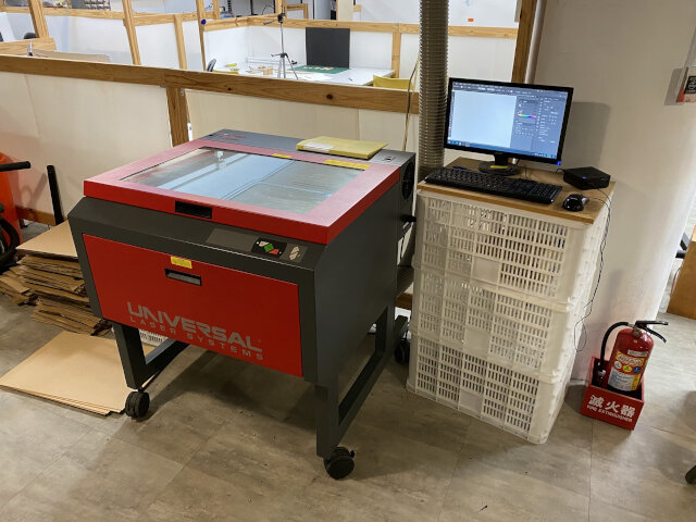
It is a single laser platform that supports either a 9.3µm CO2 or 10.6µm CO2 laser source and is capable of power output ranging from 10 to 75 watts.
The material cutting envelope is:
610 x 457 x 216 mm
Our setup has an exhaust blower with duct vented outside so no separate air filter is needed.
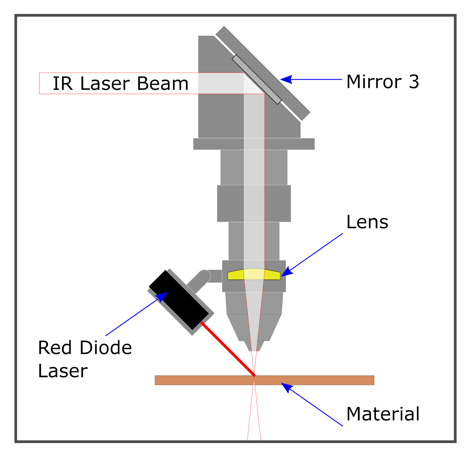
Prepping and cleaning lenses and mirrors
Over time, gunk from burnt material smoke accumulates on the inside surfaces of the laser cutter including the optics components. This affects the performance of the laser cutter as the gunk on the mirrors and focusing lens will block some of the light energy of the laser. So occasionally the laser cutter head must be taken apart to clean the mirror and lens with a cotton swab and a little bit of rubbing alcohol.
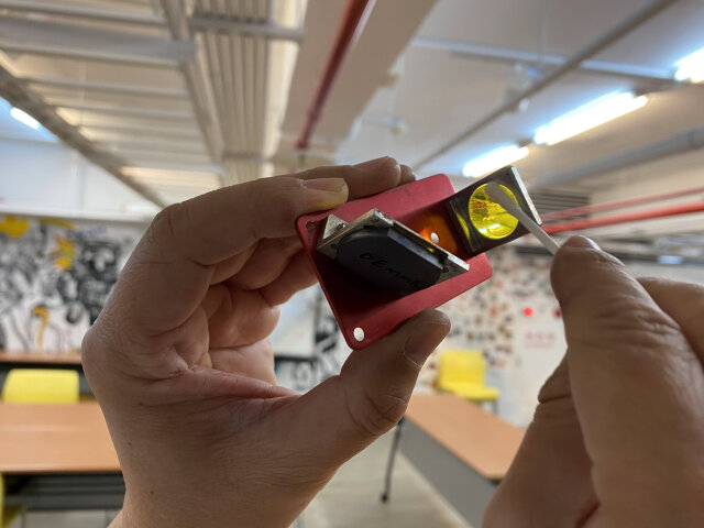
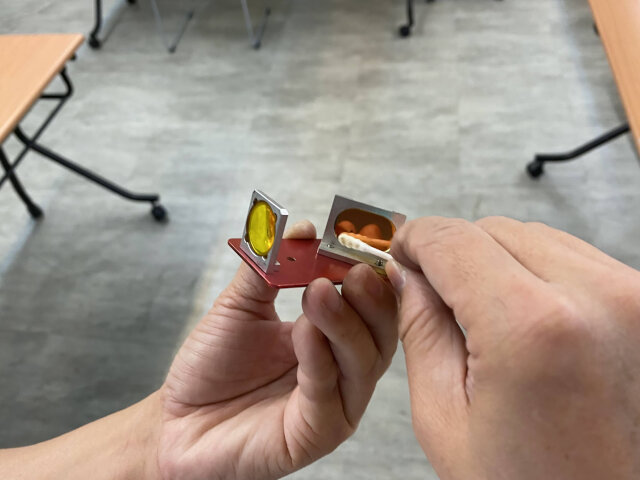
There’s also a second mirror to the left of the machine which should be cleaned, this mirror reflects the laser beam to the laser head from the top of the machine.
Once the mirrors and lenses are clean, we know for certain the power settings we set for the following experiments will be accurate.
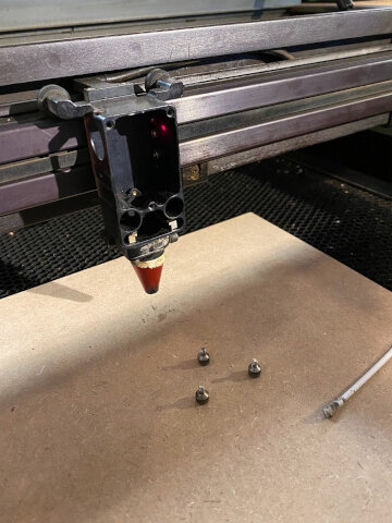
Setting focus
To set focus, we use a little tool to adjust the distance between the laser cutter head and the material to be cut. There are up and down buttons on the lower-right side of the machine to control the z-axis height of the cutting bed.
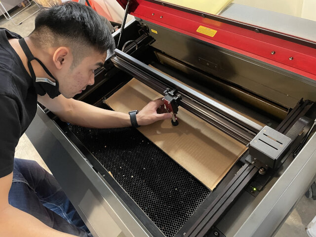
The focal length is set correctly when the ridge of the tool just touches the front edge of the laser cutter head box. This should be done every time a new material is used.
The tool is kept inside the laser cutter to the left side. There is a little hole to stick it in.
Power, Speed, Rate (PPI)
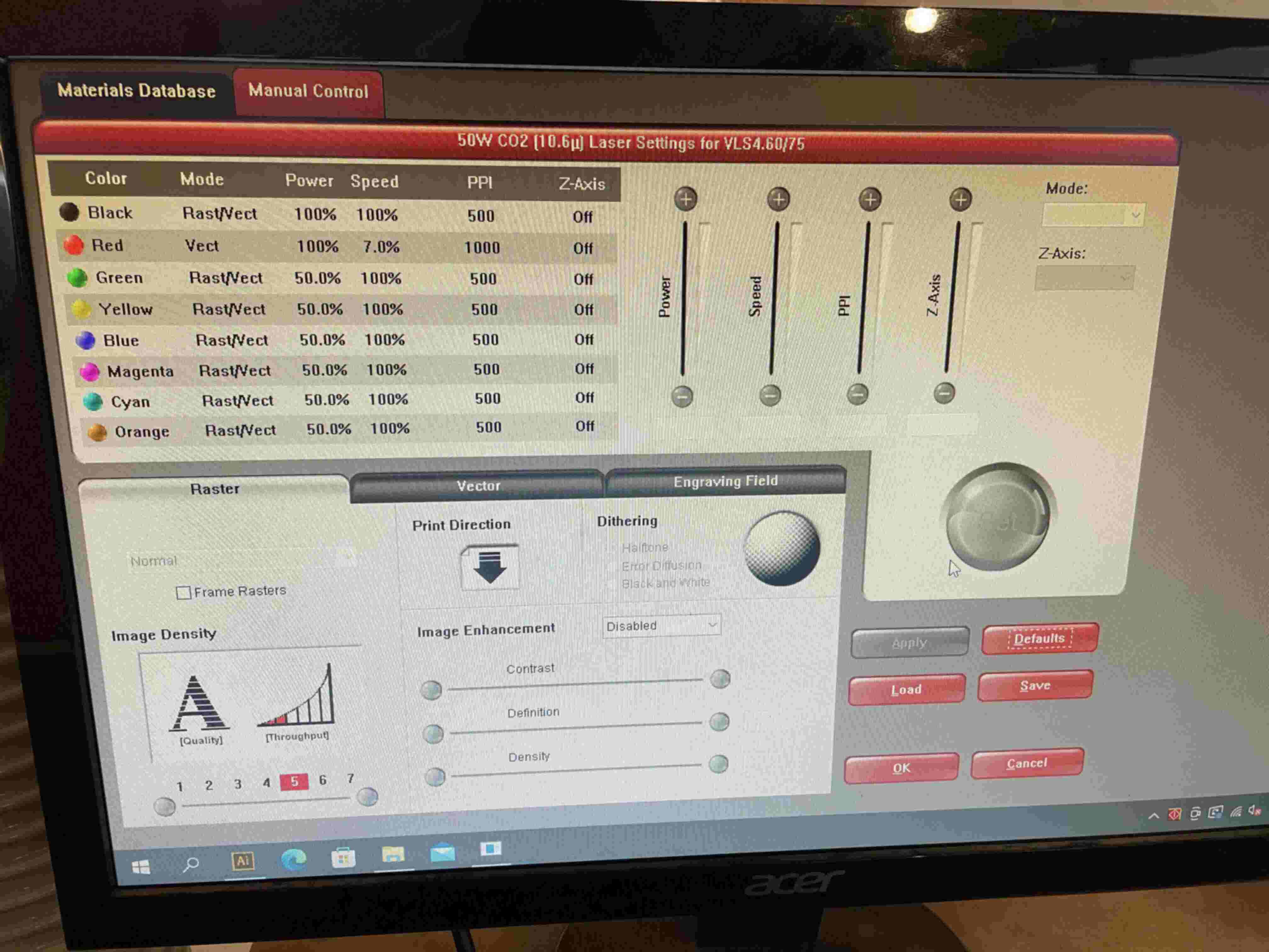
Our laser cutter can adjust power and speed (in terms of %), PPI (pulses per inch), and mode.
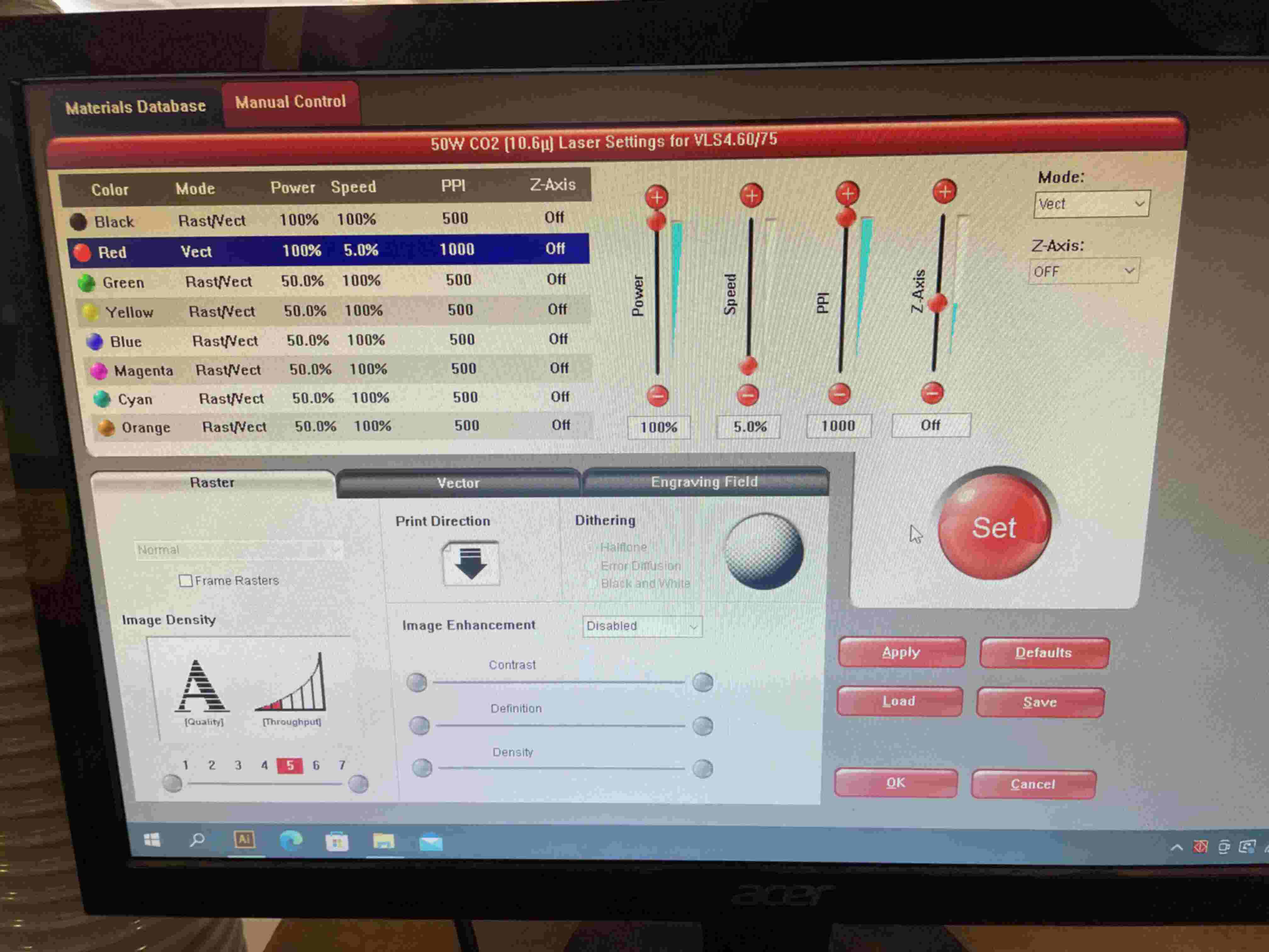
For a single drawing and cut, only up to 7 variations of power and speed can be used at once. The different settings are indicated to the cutting software by using different RGB colors in the Adobe Illustrator drawing. (Each color can only contain 0 or 255 in the RGB values for the software to recognize it)
There are two modes: Raster and Vector. This mode can be set by the user or left up to the software to decide if you put it in “rast/vect” mode. Typically, raster is used for engraving images or text on the surface of the material and vector is used for cutting through edges of a design in the material.
Rate refers to the pulse rate of the laser, or how quickly the laser beam flashes on and off as it moves (it’s not actually continuously on!). We adjust this parameter with the PPI setting. In effect, rate helps determines the amount of energy put into a given spot being cut for more accurate control. Typically for vector cut throughs we will use the max 1000 PPI, otherwise we found the default of 500 PPI works fine for raster engraving.
Joint Clearances and Kerf
Every material cuts differently and thus kerf needs to be experimentally determined for each one. The machine settings used to attain that kerf should also be noted for each material.
We don’t have a single set type of material for laser cutting here at Fablab Taipei, at the moment we have these 3 materials on hand that could be used:
- Cardboard 9mm
- MDF board, smooth surface 3mm
- MDF board, rough surface 3mm
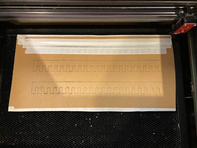
Joint clearance comb generator
We used this tool to generate “combs” link


Credit: Doyo sensei
Cardboard
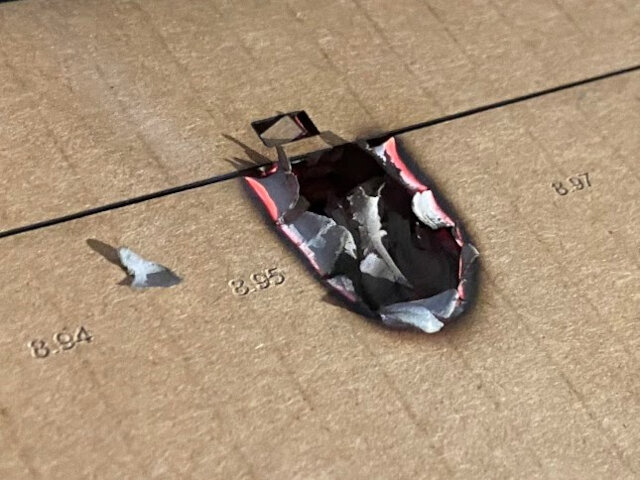
9mm cardboard is a relatively thick material to work with in the laser cutter. It requires full power and slow speed to be able to cut all the way through, however, putting this much energy into the material puts it at risk of catching on fire. Which it totally did!! Too little power though and you end up with this situation a lot:
We found that the airflow inside the laser cutter and especially around the cutting area played a significant factor in whether it caught on fire or not.
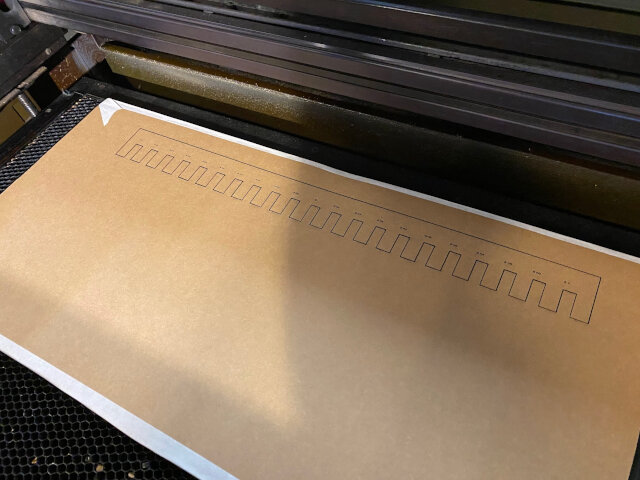
We had added a tiny “test cut” rectangle just above the joint clearance comb cutout and this was enough to introduce enough airflow to the bottom of the cardboard where the fire started propogating from.
Adding tape really helps! We discovered this technique by observing flames shoot out the vertical channels of the thick carboard. There’s still flames but it’s not growing into a fire. The air channels in the thick cardboard are cut off from feeding air into the laser area.
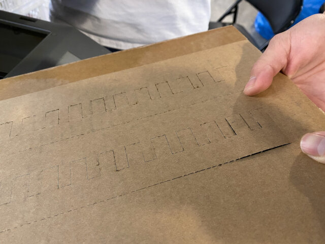
We also removed the test cut rectangle from the design since at this point we were sure of the power and speed settings. The resulting comb:
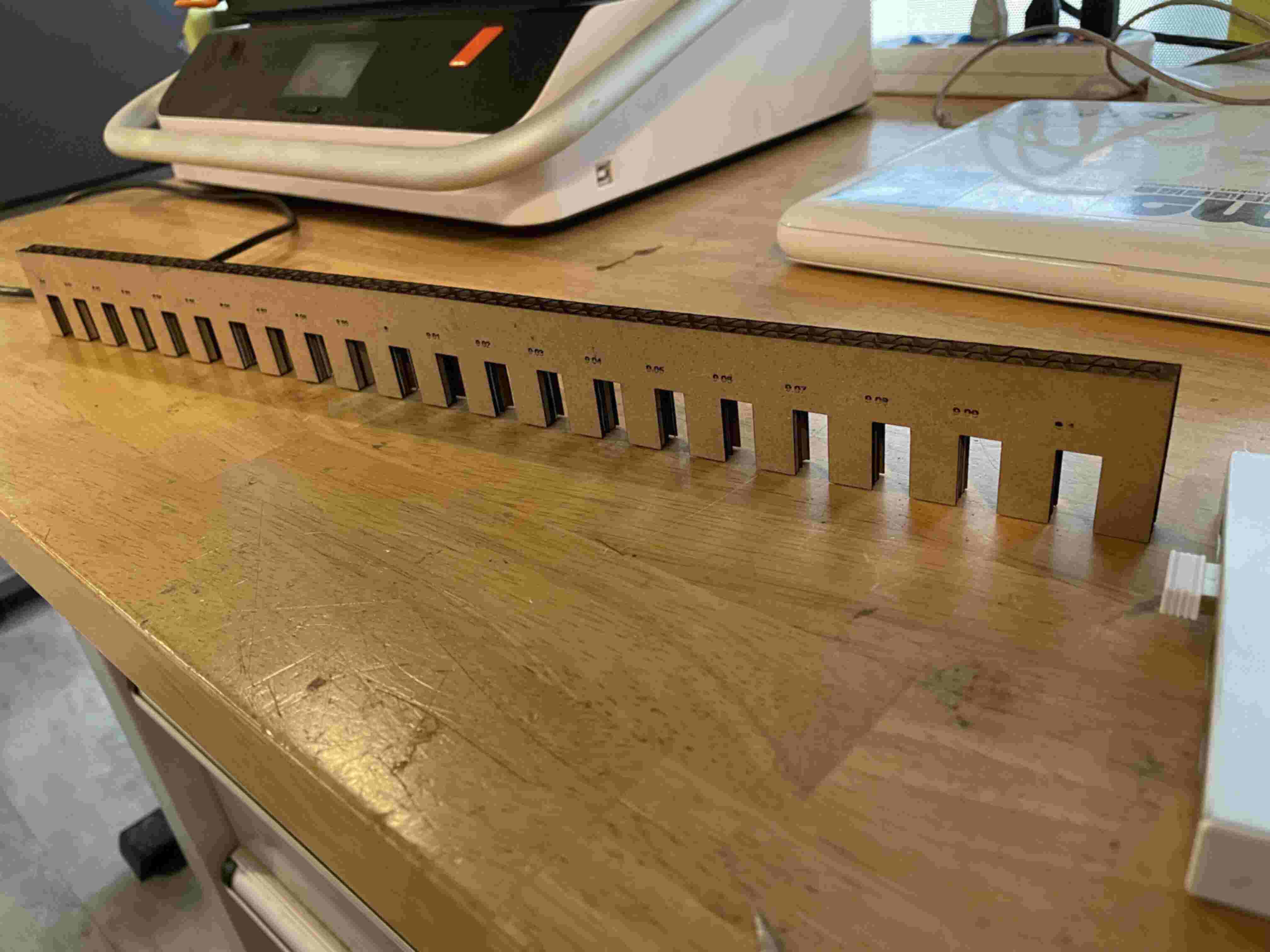
We found this cardboard to deform a lot under a press fit. The first time will be pretty snug and afterwards it’s the same loose. Generally 9.1mm was a decent press fit notch for this material though.
MDF
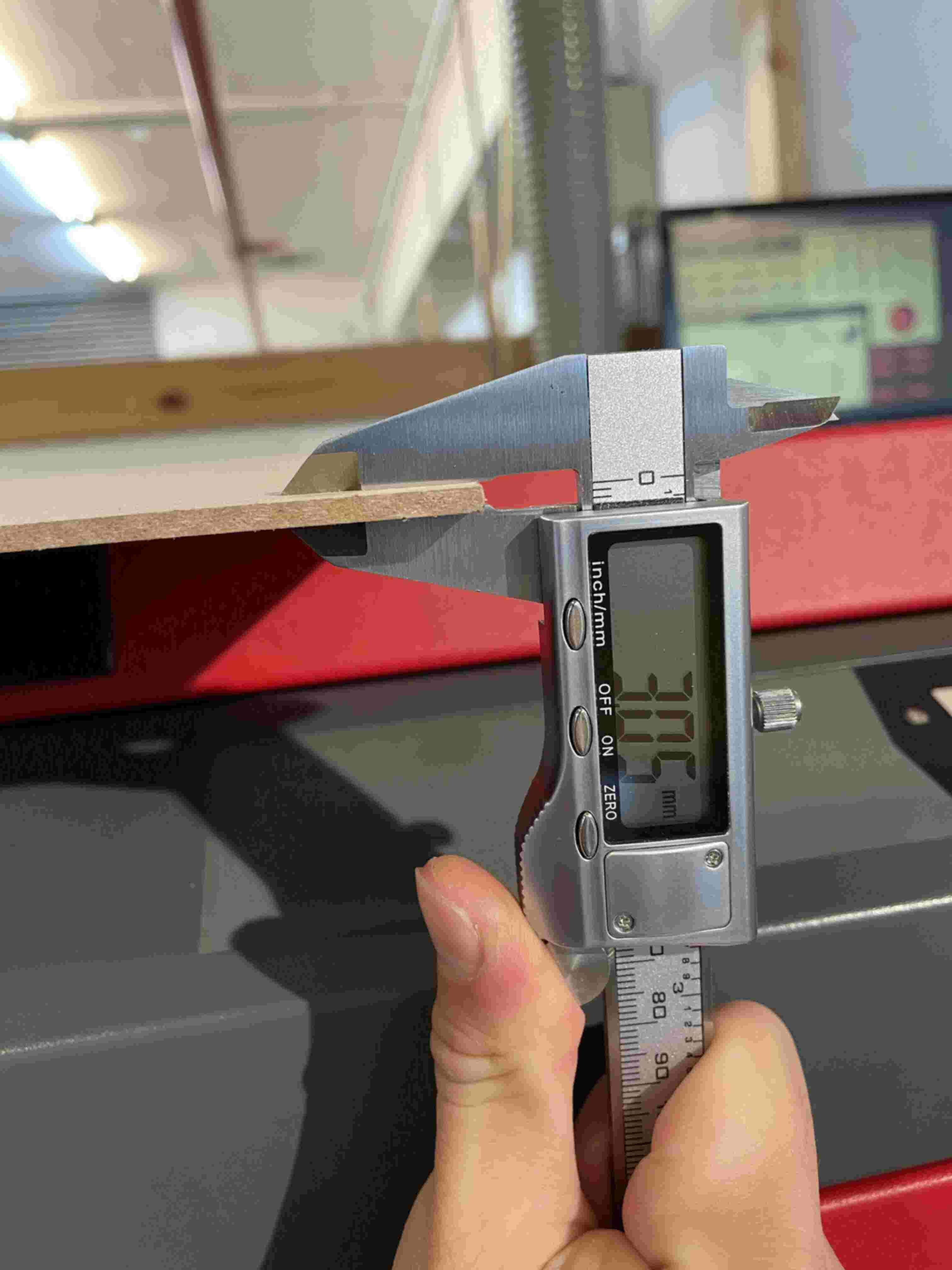
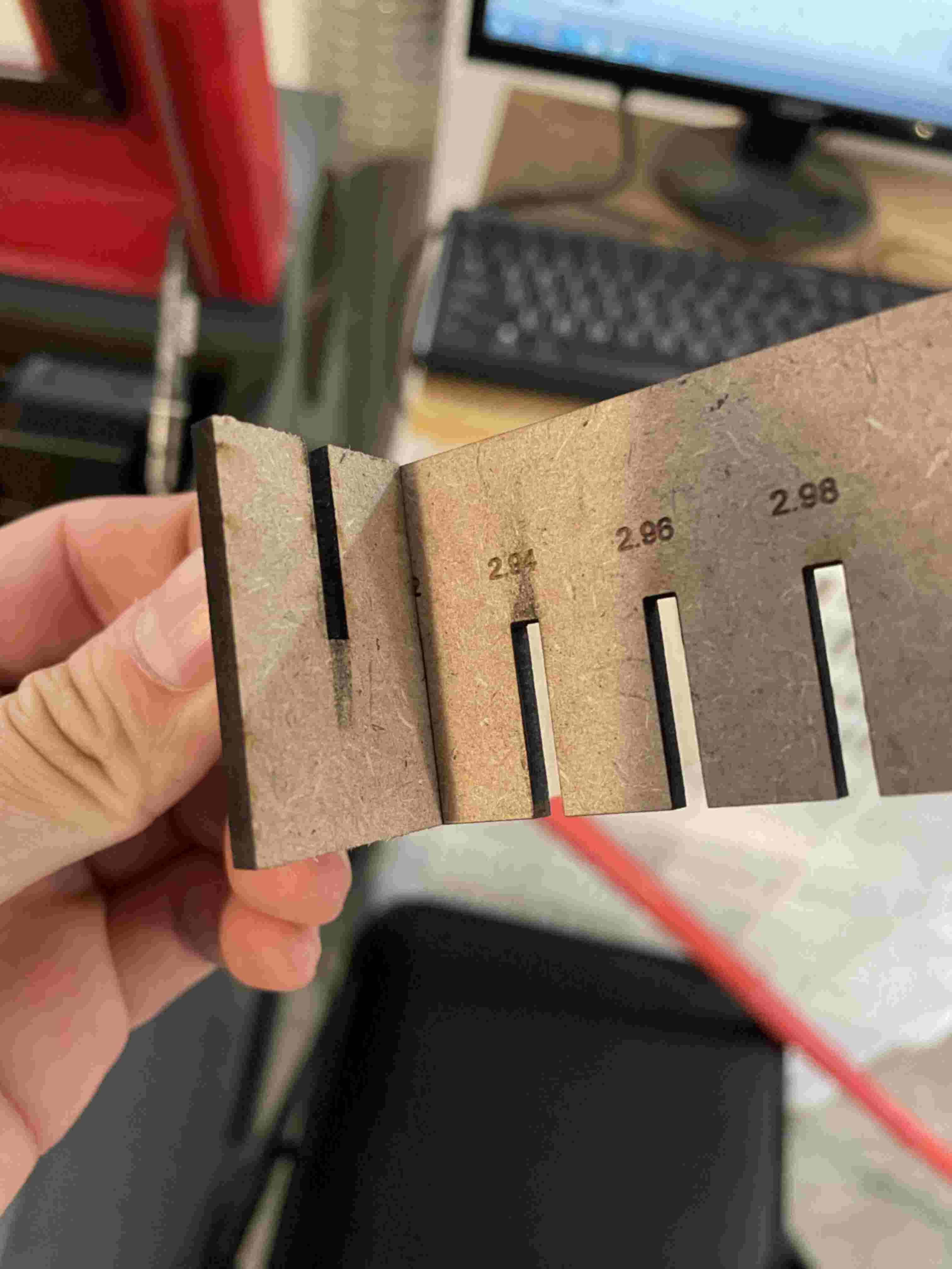
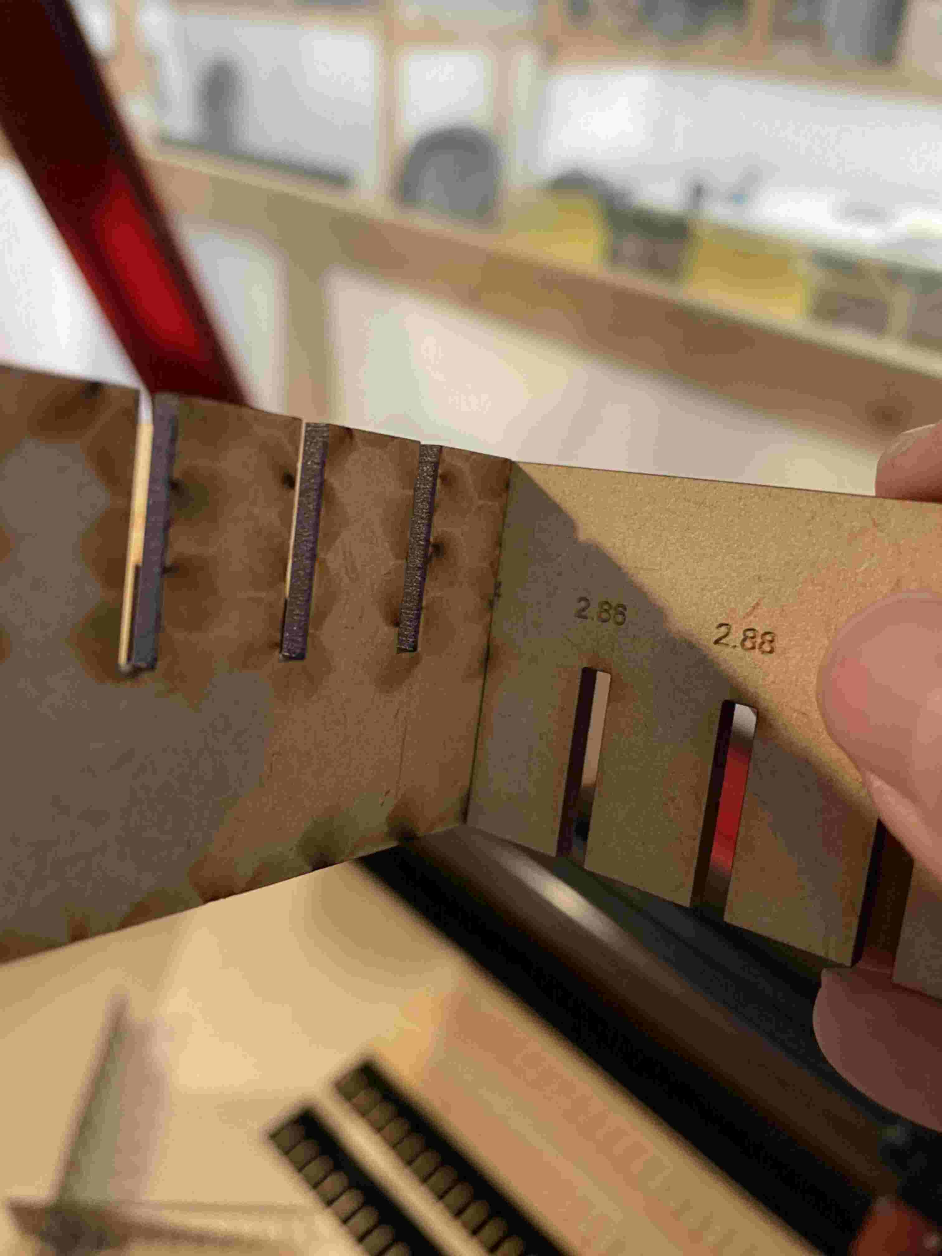
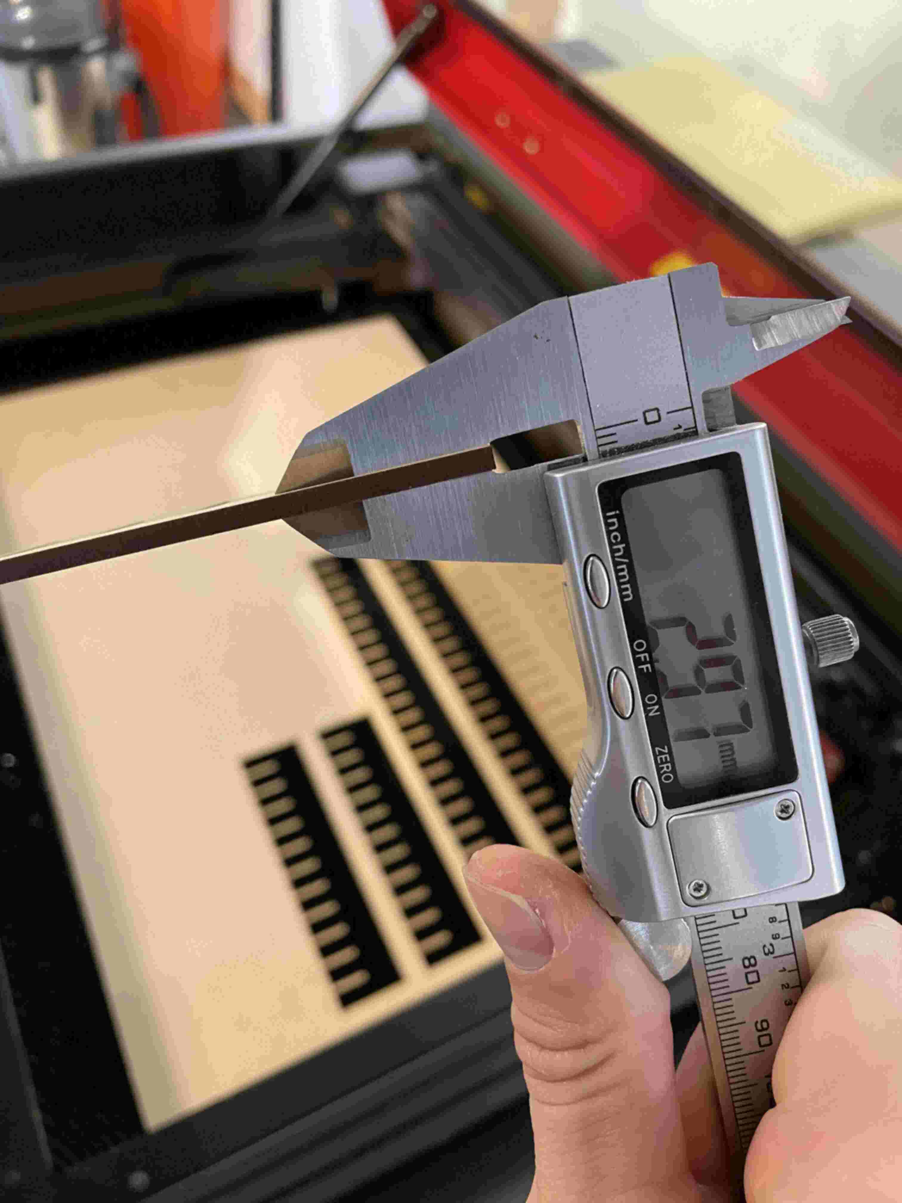
Then we try MDF with about 3mm thickness, it’s less flexible and easier to estimate the difference between “real thickness” and “printing thickness”.
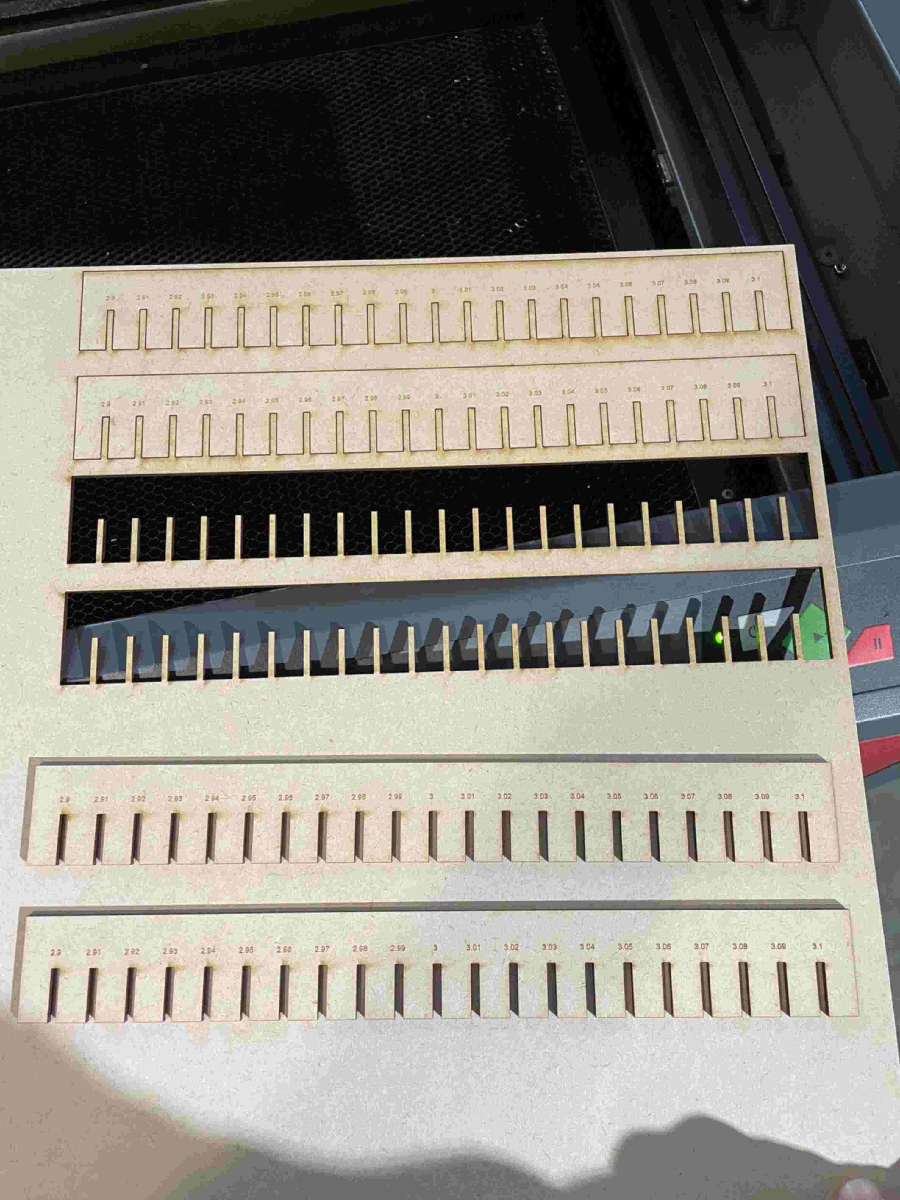
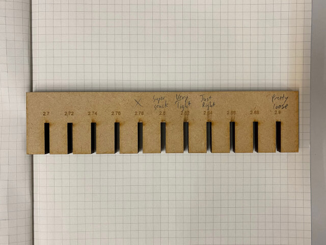
We made 2 experiments with the two different MDFs available here. One was 3.05mm and the other was about 2.97mm. For a interlocking press fit as shown by the comb experiment, 2.84mm is just right.
Thus the result is kerf = 0.13 mm However, if a tighter press fit is desired, kerf can be increased as a parameter used in CAD calculations.
Final settings used:
(Red color is for cutting through)
It’s really cool to see laser cutting!