14. Networking and communications
REVIEW OF THE CLASS
Network
A computer network is a collection of two or more computer systems that are linked together. A network connection can be established using either cable or wireless media. Hardware and software are used to connect computers and tools in any network. A computer network consists of various kinds of nodes. Servers, networking hardware, Personal computers, and other specialized or general-purpose hosts can all be nodes in a computer network.
Wired/Wireless Networking
On basis of physical medium, there are 2 types of networks:
a. Wired Network: As we all know, “wired” refers to any physical medium made up of cables. Copper wire, twisted pair, or fiber optic cables are all options. A wired network employs wires to link devices to the Internet or another network, such as laptops or desktop PCs. 1. Synchronous Network:
A synchronous network is the one where data is transmitted and received at the same time. It is also known as Full-Duplex.
- Asynchronous Network:
An asynchronous Network does not use a single clock to receive or transmit data. The data flows in only one direction at a time. This is also known as Half-duplex. Example: Walkie-Talkie
3PINS- RX, TX, GND
- SPI( serial peripheral interface):
SPI is a serial and synchronous communication protocol. This protocol works best for short-range communication only. SD card modules, radio modules, RFID modules, etc. use this protocol.
Just like I2C, SPI communication uses master and slave devices. One master device can control multiple slaves but not the other way around.
4PINS- MISO,MOSI, SCK, CS
- I2C: I2C stands for Inter-Integrated Circuit. It is a bus interface connection protocol incorporated into devices for serial communication and idely used protocol for short-distance communication.
Working of I2C Communication Protocol :
It uses only 2 bi-directional open-drain lines for data communication called SDA and SCL. Both these lines are pulled high.
- Serial Data (SDA) – Transfer of data takes place through this pin.
- Serial Clock (SCL) – It carries the clock signal.
b. Wireless Network: “Wireless” means without wire, media that is made up of electromagnetic waves (EM Waves) or infrared waves. Antennas or sensors will be present on all wireless devices. Cellular phones, wireless sensors, TV remotes, satellite disc receivers, and laptops with WLAN cards are all examples of wireless devices. For data or voice communication, a wireless network uses radiofrequency waves rather than wires.
- Wifi
- Bluettoth
Wifi
Wi-Fi is a wireless networking technology that allows devices such as computers (laptops and desktops), mobile devices (smart phones and wearables), and other equipment (printers and video cameras) to interface with the Internet. It allows these devices–and many more–to exchange information with one another, creating a network.
Internet connectivity occurs through a wireless router. When you access Wi-Fi, you are connecting to a wireless router that allows your Wi-Fi-compatible devices to interface with the Internet. source: wikipedia
How wifi work?
The main requirement for Wi-Fi is a device that receives and transmits a wireless signal, usually a router, and sometimes a phone or computer. WiFi-enabled devices communicate with one another by sending and receiving radio waves, a type of electromagnetic radiation with wavelengths in the electromagnetic spectrum longer than infrared light. More specifically, they use either the 2.4 GHz or the 5 GHz frequency.
 source:purevpn.com
Bluetooth
Bluetooth is a short-range wireless technology standard that is used for exchanging data between fixed and mobile devices over short distances using UHF radio waves in the ISM bands, from 2.402 GHz to 2.48 GHz, and building personal area networks (PANs). It is mainly used as an alternative to wire connections, to exchange files between nearby portable devices and connect cell phones and music players with wireless headphones. In the most widely used mode, transmission power is limited to 2.5 milliwatts, giving it a very short range of up to 10 metres (33 ft).
Assignment
Individual assignment:
Design, build, and connect wired or wireless node(s) with network or bus addresses
group assignment:
send a message between two projects.
For the Group Assignment Refer here
Objectives of the week
- Design Board
- Connect ESP32 to wifi
- Group assignment
- Build the web server to controls two LEDs connected to the ESP32 GPIO.
- Access the ESP32 web server by typing the ESP32 IP address on a browser in the local network.
- Control the LED stats by clicking the ON/OFF buttons on your web server.
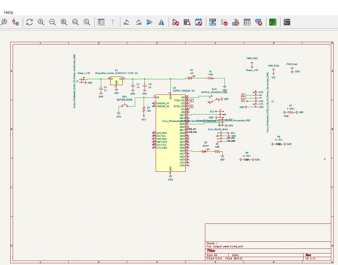
BOARD DESIGNING.
I have used the same board which was used during my input and output week.
Schematic Design
Board Design
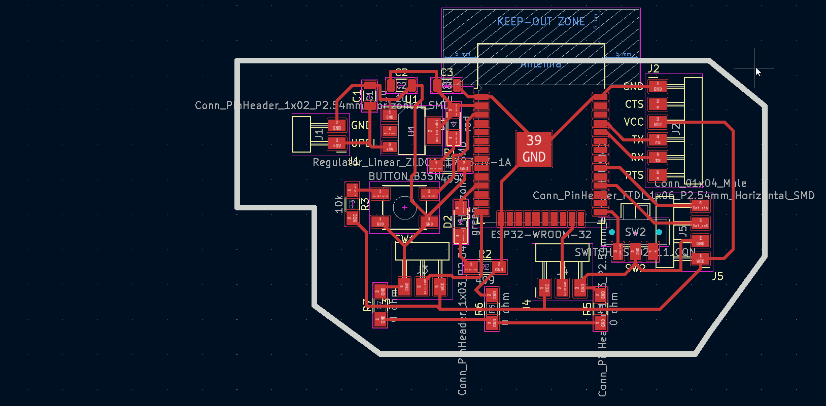
For this assignment I will control LEDs using ESP32 web server in Arduino IDE. and try to communicate between two ESP32 by ESP NOW Protocol
CONNECT ESP32 TO WiFi
If you are using ESP32 for the final project or for any other project, it is the first step to connect ESP32 to wifi.
To connect Esp to Wifi, open Arduino IDE software >> go to file >> examples >> wifi >> simple wifi server/ wifi scan.
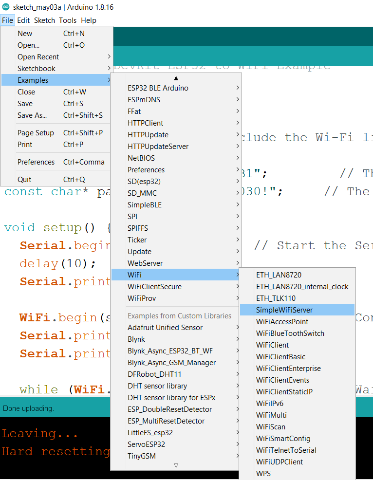
Then enter the ‘SSID and the password’ of the network you want to connect to, and call the function.
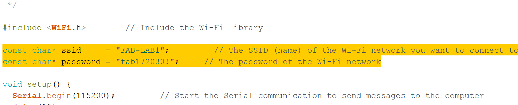
Wait for the connection to complete.
Now the ESP32 board is connected to wifi.
Programming ESP32 BOARD.
To program the ESP board, first you have to SETUP ESP32 ENVIRONMENT FOR ARDUINO IDE.
For that refer here
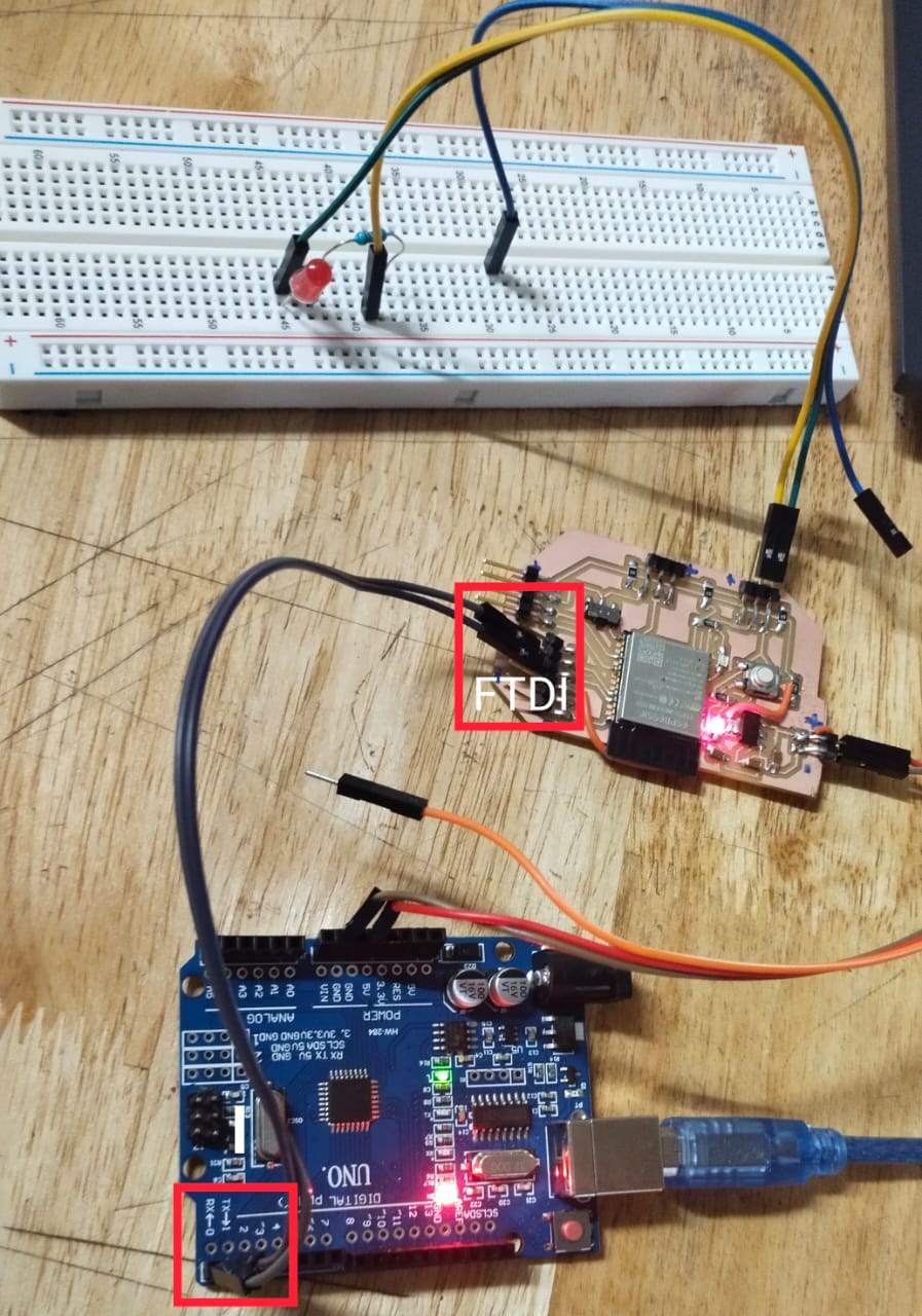
I have used the FTDI cable to programme my board.
I have used the Arduino Board to load my program and then made it as FTDI to load the program to my board.
I have used the blank code below to make the arduino as FTDI
void setup(){
    pinMode(0,INPUT);
    pinMode(1,INPUT);
    }
    void loop(){
    }
This is simple arduino code that makes RX and TX pin of the arduino as output pin.
Now connect ESP board to power supply and connect RX and TX pin of arduino with RXD 0 and TXD 0 pins of ESP32 respectively.
To make the circuit connection, connect a led to the esp32 as shown in the following diagram. I have connected my led to GPIO 12
CODE
I have used a simple code to blink LED from example programme given in Arduino IDE.
// the setup function runs once when you press reset or power the board
void setup() {
  // initialize digital pin LED_BUILTIN as an output.
  pinMode(12, OUTPUT);
}

// the loop function runs over and over again forever
void loop() {
  digitalWrite(12, HIGH);   // turn the LED on (HIGH is the voltage level)
  delay(1000);                       // wait for a second
  digitalWrite(12, LOW);    // turn the LED off by making the voltage LOW
  delay(1000);                       // wait for a second
}
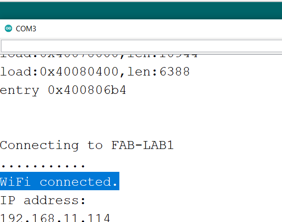
Compile and upload the code. Use the IP address given in the serial monitor
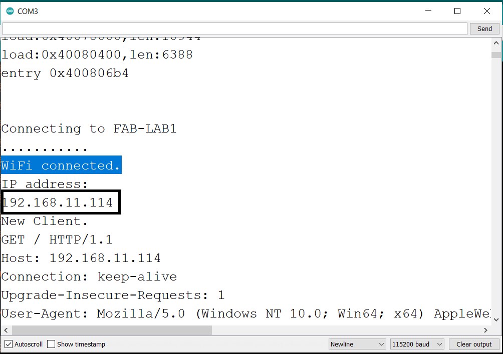
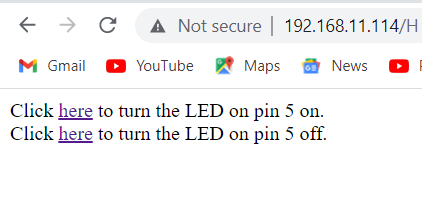
Paste it in a web browser, in my case it’s 192.168.11.114

and control the led on the bread board.
Testing Results with Web Server
To test whether the web server is working properly, I clicked the buttons to control the led.
And it was working fine.
Original Files
Download all the original files from here.
Initially I have tried to control LED using the IP address from web server but during Global evalution I got a comment saying “You need to communicate between two or more boards with identifiable addresses wired or wireless.” Therefore, I will try to communicate between two ESP32 board.
ESP32 ESP-NOW One-Way and Two-Way Communication (Arduino IDE)
What is ESP-NOW Protocol?
ESP-NOW is another protocol developed by Espressif, which can perform one way or two way communication between ESP MCU devices without using a Wi-Fi network. It allows transfer of small peer to peer wireless data packets. Only upto 250 bytes of data can be transferred. the ESP-NOW uses the same 2.4 GHz band as the Wi-Fi but does not need to connect or interfere with the local network connection. It is a fast and convenient communication protocol for the transmission of a smaller amount of data. The ESP-NOW uses the same 2.4 GHz band as the Wi-Fi but does not need to connect or interfere with the local network connection. It is a fast and convenient communication protocol for the transmission of a smaller amount of data.
ESP-NOW Networking Modes
We can make the ESP-NOW network in many configurations. We can mix and match ESP32 and ESP8266 devices within the same network. In ESP-NOW network we have to create a initiators and responders.
Initiators and Responders
A device participating in an ESP-NOW network can be operated in one of two modes.
Initiator – This device initiates the transmission. It will require the MAC address of the receiving device. Responder – This device receives the transmission.
In unidirectional (half-duplex) mode, the transmitting device is the Initiator and the receiving device is the Responder.
In a 2-way (full-duplex) communications mode, each device is both an Initiator and Responder.
One-Way Communication OR half-duplex communication.
In one-way communication, the initiator ESP32 transmits data to the Responder ESP32. We can tell if the responder received the message successfully or not.
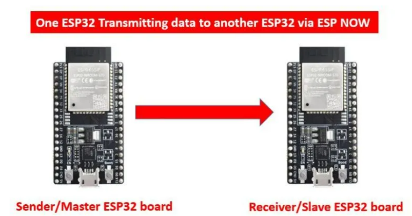 image source: google
Two- way communication or Full-Duplex communication.
In this communication, both the device can communicate with eachother at the same time.
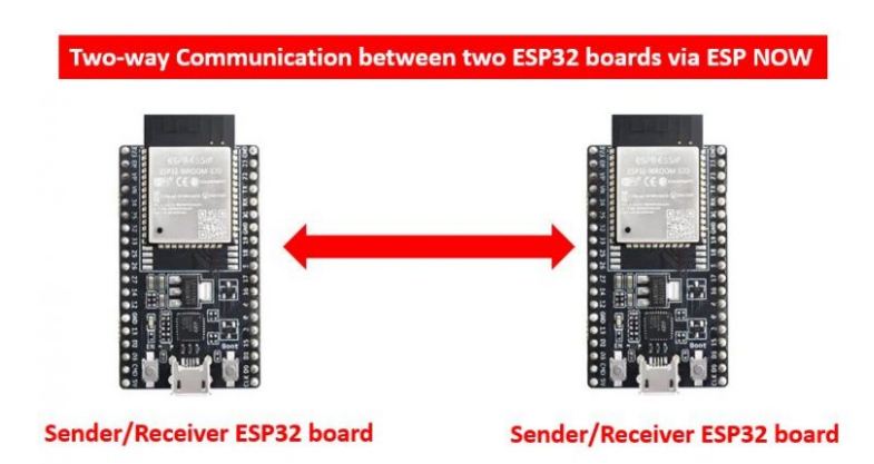 image source: google
MAC Addresses
A mac address is required to make the communication possible between the initiator and the responder.
A MAC, or Media Access Control, Address is a unique 6-digit hexadecimal number assigned to every device on a network. It is generally burned into the device by the manufacturer, although it is possible to manually set it. Today we will be working with ESP-NOW, a connectionless protocol developed by Espressif for the ESP32 and ESP08266 microcontrollers. With ESP-NOW we can build a private network without WiFi or a Router.
For one way communication I am going to send some data from initiator to the responder. For that I need to get MAC address.
MAC Address
Copy the code below and run it on Arduino IDE to get the MAC address
// Include WiFi Library
#include "WiFi.h"

void setup() {

  // Setup Serial Monitor
  Serial.begin(115200);

  // Put ESP32 into Station mode
  WiFi.mode(WIFI_MODE_STA);

  // Print MAC Address to Serial monitor
  Serial.print("MAC Address: ");
  Serial.println(WiFi.macAddress());
}

void loop() {

}
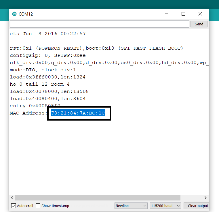
Copy the MAC address and keep it at a safe loction for the later use.
Once your the MAC address it is time for coding. Make sure all the necessary libraries were installed in your arduino ide. If you are going to do the same example of what I have used, I will give all the library links at the end.
Coding for ESP-NOW – Sending
Mark one ESP as sender and other as receiver.
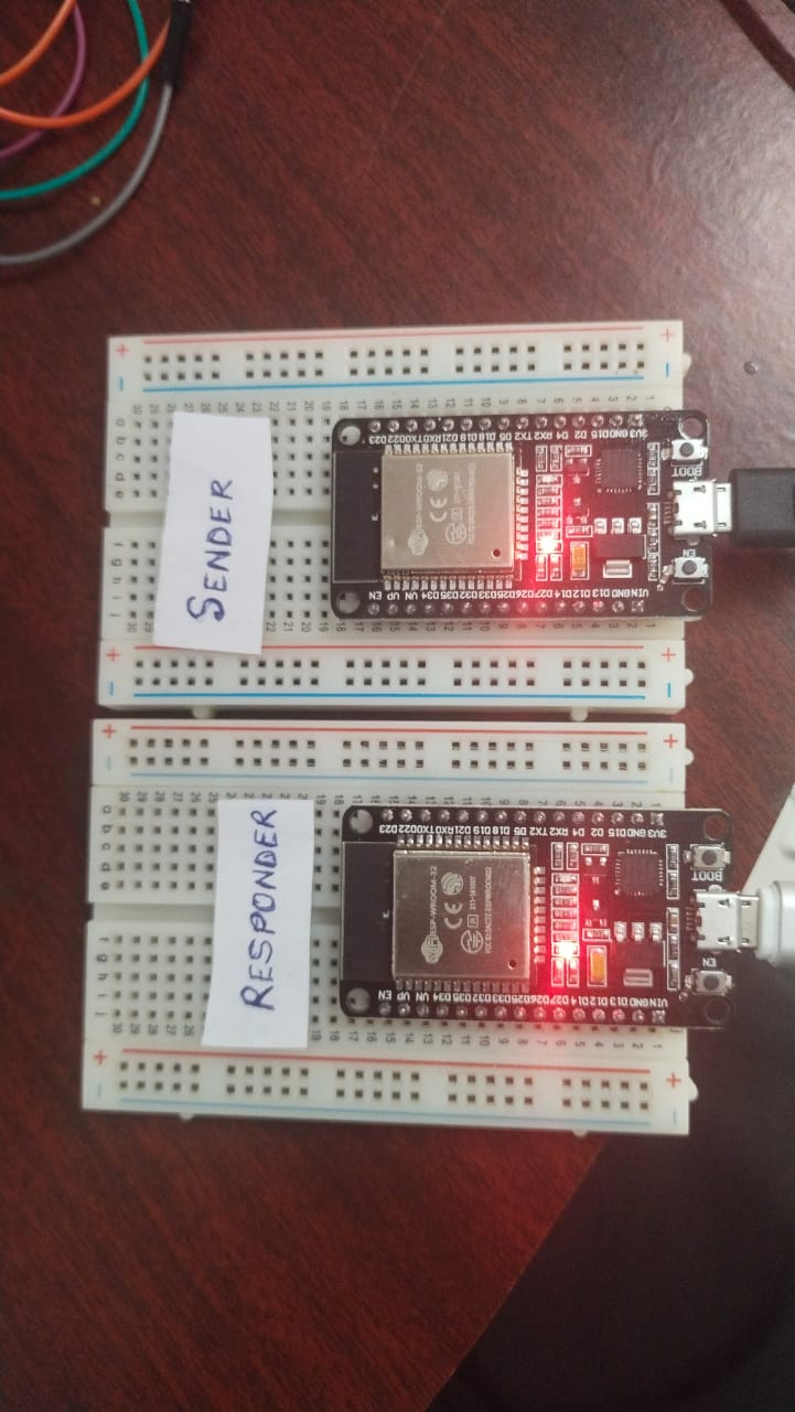
Since, I am away from lab I am using the commercially available ESP board for this assignment.
For the sender board you have to - initialize the ESP-NOW library. - Next, you’ll register your send callback function
  In the ESP-NOW protocol, there are two callbacks of interest:

1. Sending Data – The esp_now_register_send_cb() callback is called whenever data is sent.
2. Receiving Data – The esp_now_register_rcv_cb() callback is called when data is received.

The callback functions also return some useful data:

- The Sending callback returns the status of the sent data.
- The Receiving callback includes the received data packet.
- You need to add a peer device, which is the responder device. You add the peer by specifying its MAC address.
- Finally, you can packetize and send the message.
code for ONE-WAY Initiator
Open a new Arduino IDE page to write the code for one way initiator and save it as ESP32#1.
copy the code below, replace the MAC address with the one you saved earlier and run the sketch.
// Include Libraries
#include <esp_now.h>
#include <WiFi.h>

// Variables for test data
int int_value;
float float_value;
bool bool_value = true;

// MAC Address of responder - edit as required
uint8_t broadcastAddress[] = {0x78, 0x21, 0x84, 0x7A, 0xBC, 0x1C};

// Define a data structure
typedef struct struct_message {
  char a[32];
  int b;
  float c;
  bool d;
} struct_message;

// Create a structured object
struct_message myData;

// Peer info
esp_now_peer_info_t peerInfo;

// Callback function called when data is sent
void OnDataSent(const uint8_t *mac_addr, esp_now_send_status_t status) {
  Serial.print("\r\nLast Packet Send Status:\t");
  Serial.println(status == ESP_NOW_SEND_SUCCESS ? "Delivery Success" : "Delivery Fail");
}

void setup() {

  // Set up Serial Monitor
  Serial.begin(115200);

  // Set ESP32 as a Wi-Fi Station
  WiFi.mode(WIFI_STA);

  // Initilize ESP-NOW
  if (esp_now_init() != ESP_OK) {
    Serial.println("Error initializing ESP-NOW");
    return;
  }

  // Register the send callback
  esp_now_register_send_cb(OnDataSent);

  // Register peer
  memcpy(peerInfo.peer_addr, broadcastAddress, 6);
  peerInfo.channel = 0;
  peerInfo.encrypt = false;

  // Add peer
  if (esp_now_add_peer(&peerInfo) != ESP_OK){
    Serial.println("Failed to add peer");
    return;
  }
}

void loop() {

  // Create test data

  // Generate a random integer
  int_value = random(1,20);

  // Use integer to make a new float
  float_value = 1.3 * int_value;

  // Invert the boolean value
  bool_value = !bool_value;

  // Format structured data
  strcpy(myData.a, "Kencho network and communication week");
  myData.b = int_value;
  myData.c = float_value;
  myData.d = bool_value;

  // Send message via ESP-NOW
  esp_err_t result = esp_now_send(broadcastAddress, (uint8_t *) &myData, sizeof(myData));

  if (result == ESP_OK) {
    Serial.println("Sending confirmed");
  }
  else {
    Serial.println("Sending error");
  }
  delay(2000);
}
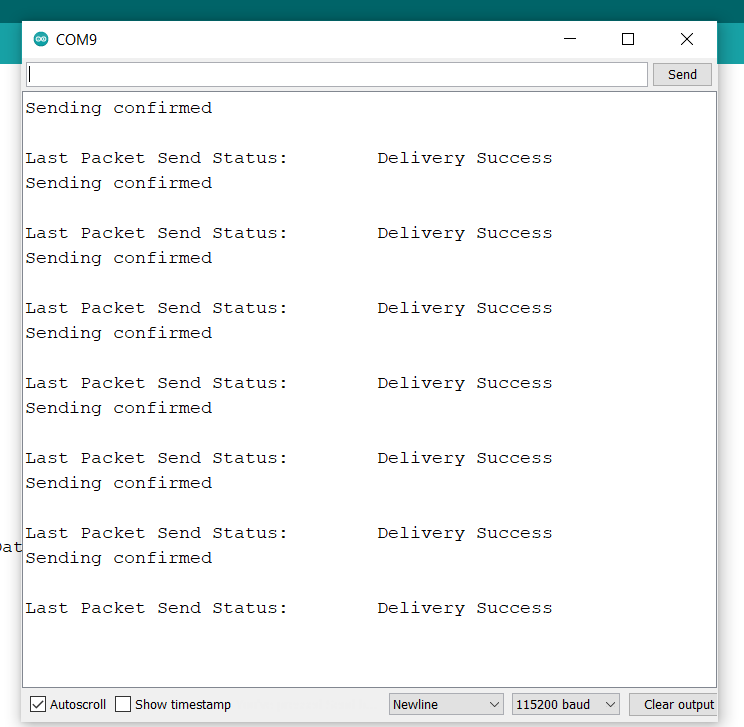
Once the code is loaded, open the serial monitor and press the EN button to refresh it.
Something like this will be printed. This means the datas are sucessfully transferred to the responder.
Now lets prepare the responder by registering the received callback function. In the receive callback function we will capture the incoming message data and pass it to a variable.
CODE for One-Way Responder
// Include Libraries
#include <esp_now.h>
#include <WiFi.h>

// Define a data structure
typedef struct struct_message {
  char a[32];
  int b;
  float c;
  bool d;
} struct_message;

// Create a structured object
struct_message myData;


// Callback function executed when data is received
void OnDataRecv(const uint8_t * mac, const uint8_t *incomingData, int len) {
  memcpy(&myData, incomingData, sizeof(myData));
  Serial.print("Data received: ");
  Serial.println(len);
  Serial.print("Character Value: ");
  Serial.println(myData.a);
  Serial.print("Integer Value: ");
  Serial.println(myData.b);
  Serial.print("Float Value: ");
  Serial.println(myData.c);
  Serial.print("Boolean Value: ");
  Serial.println(myData.d);
  Serial.println();
}

void setup() {
  // Set up Serial Monitor
  Serial.begin(115200);

  // Set ESP32 as a Wi-Fi Station
  WiFi.mode(WIFI_STA);

  // Initilize ESP-NOW
  if (esp_now_init() != ESP_OK) {
    Serial.println("Error initializing ESP-NOW");
    return;
  }

  // Register callback function
  esp_now_register_recv_cb(OnDataRecv);
}

void loop() {

}
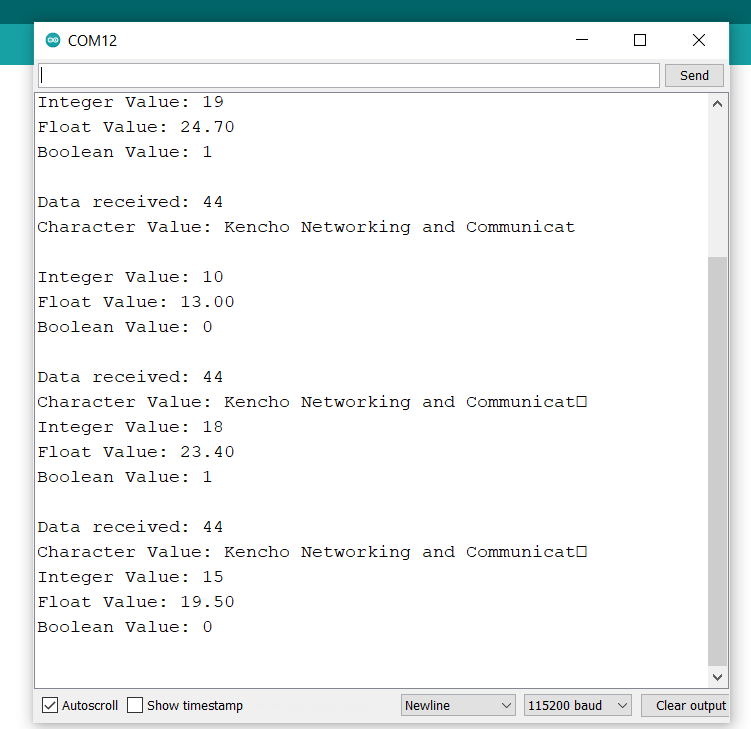
copy this code and load it in a new sketch on the arduino ide. Once the code is loaded, open the serial monitor at baud reate 115200. You should receive the data send from the Sender ESP32.
One-Way communication Files
Download all the One-Way original files from here.