9. Embedded programming
What is Embedded systems?
To understand the concept of embedded system first we have to understand what it’s meant by system.
Systems- It is an arrangement in which all it’s units, assembled work together according to set of rules. Eg. Watch is time displaying system.
Embedded system: It is a combination of software and hardware.
It is designed to perform a particular task.
The task has to be completed in a given time.
Eg. Mobile phone, washing machine, micro oven.
Group Assignment
For the group assignment of the week refer THIS LINK.
Individual Assignment:
Task 1. Read the data sheet for your microcontroller.
Task 2. Use your programmer to program your board to do something.
Before reading the datasheet of the microcontroller that I have used for my assignment, let me share the basics ideas that we have to know for designing our board.
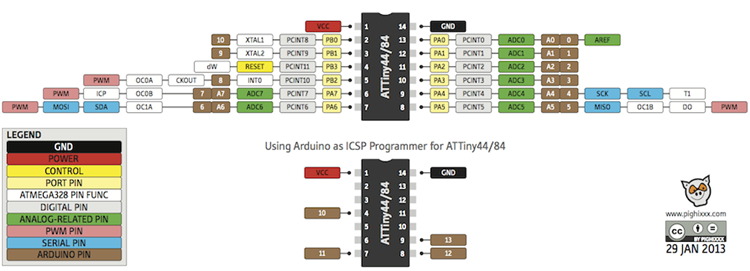
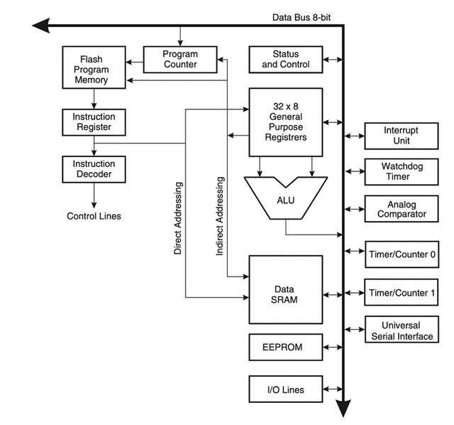
Architecture:
They are of two types; Harvard architecture and Von Neumann.
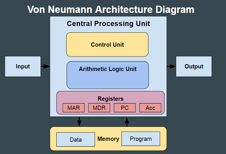
Von Neumann: Data and Code lie in same memory block.
One data or bus is used for both instructions and data. As a result CPU can perform only one operation at a time.
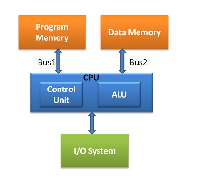
Harvard architecture: When data and code lie in different memory block.
It uses separate buses for both instructions and data.
This architecture has data storage entirely contained in with the CPU.
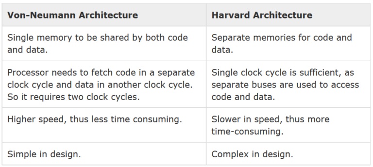
Differences between two architecture.
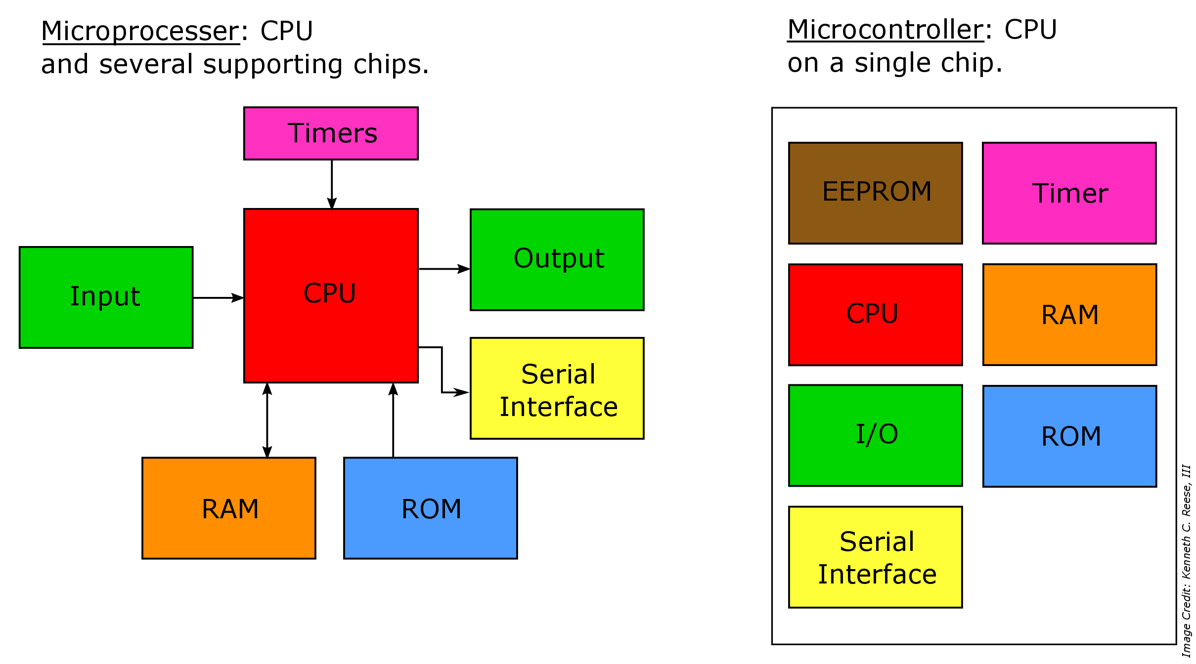
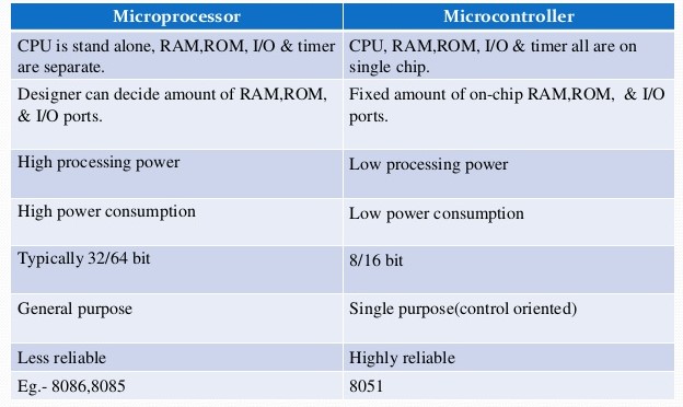
Differences between Microprocessor and Microcontroller
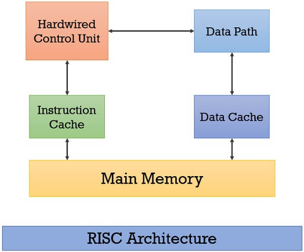
What is RISC?
RISC, or Reduced Instruction Set Computer; is a type of microprocessor architecture that utilizes a small, highly-optimized set of instructions, rather than a more specialized set of instructions often found in other types of architectures.
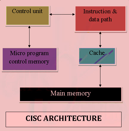
What is CISC?
CISC stands for “Complex Instruction Set Computing.” This is a type of microprocessor design. The CISC architecture contains a large set of computer instructions that range from very simple to very complex and specialized.
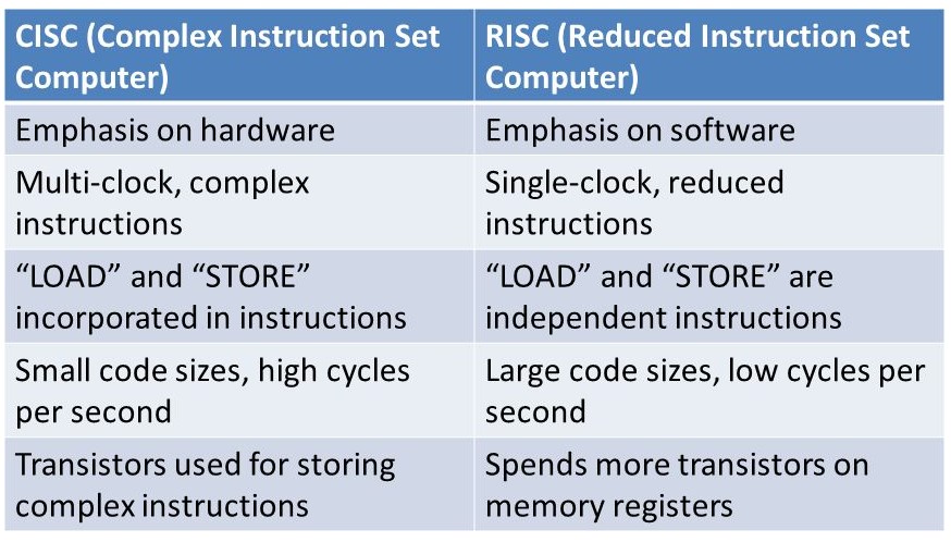
Differences between RISC and CISC?
AVR microcontrollers:
MicroController:
We can say that the microcontrollers are the advanced versions of the microprocessors. It contain on chip central processing unit (CPU), Read only memory (ROM), Random access memory (RAM), input/output unit, interrupts controller etc.
Therefore a microcontroller is used for high speed signal processing operation inside an embedded system. It acts as major component used in designing of an embedded system.
AVR microcontroller:
is an electronic chip manufactured by Atmel, which has several advantages over other types of microcontroller.
We can understand microcontroller by comparing it with Personal Computer (PC), which has a motherboard inside it. In that motherboard a microprocessor (AMD, Intel chips) is used that provides the intelligence, EEPROM and RAM memories for interfacing to the system like serial ports, display interfaces and disk drivers. A microcontroller has all or most of these features built into a single chip, therefore it doesn’t require a motherboard and any other components.
How to Read Datasheet?
Datasheet: A datasheet is a document providing the specificaions and details of a particular product.
Datasheet is used as a refernece than a manual for using a microcontroller or the device. Its function is similar to that of using a dictionary to search for a particular word meaning. We just needs to learn how to use and refer to it to understand the microcontroller or the device such that it suits their application.
Datasheets are like biography or instruction manuals for the electronic component. They guide the users what each component does and how to use it.
In my circuit daigram I have used ATtiny 44 and for my final project I will be using ESP32.
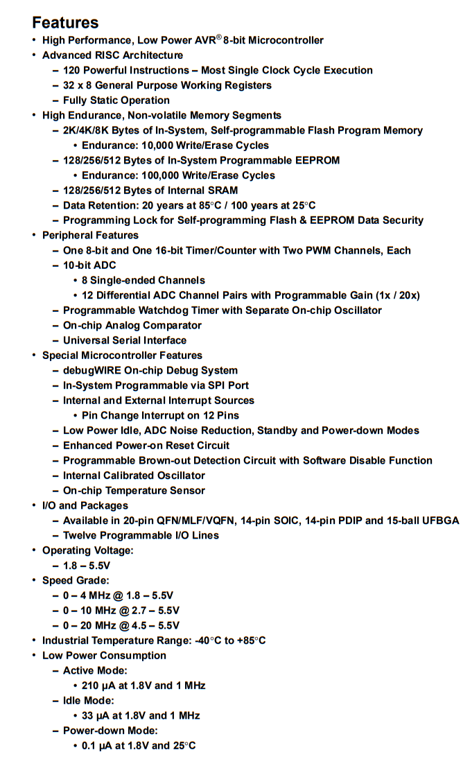
ATtiny44 Datasheet.
ATtiny44 is a High Performance, Low Power AVR® 8-bit, RISC-based Microcontroller that combines:
- 4KB ISP flash memory,
- 256-Byte EEPROM,
- 256B SRAM,
- 12 programmable I/O lines,
- 32*8 general purpose working registers,
- one 8-bit and one 16-bit timer/counter,
- USI (universal serial interface), internal and external Interrupts,
- 8-channel 10-bit Analog to Digital converter,
- programmable watchdog timer with internal oscillator,
- debugWIRE for on-chip debugging and
- operates between 1.8-5.5 volts.
- By executing powerful instructions in a single clock cycle, the device achieves throughputs approaching 1 MIPS per MHz, allowing the system designer to optimize power consumption versus processing speed.
CPU(central processing unit) ensures correct program execution by accessing memories, performing calculations, controlling peripherals, and handling interrupts.
There are three types of memory Flash stores the compiled program even when the power is off.
SRAM saves temporarily variables while calculating
EEPROM is for data storage
ATtiny44A features successive approximation Analog-to-Digital Converter (ADC). It generates a 10-bit result which is presented in the ADC Data Registers, ADCH and ADCL. ADCL presents only the low byte of the ADC conversion result and ADCH presents only the high byte. ADCL is read first, then ADCH. When ADCH is read, ADC access to the ADCH and ADCL Registers is re-enabled and a new result is provided.
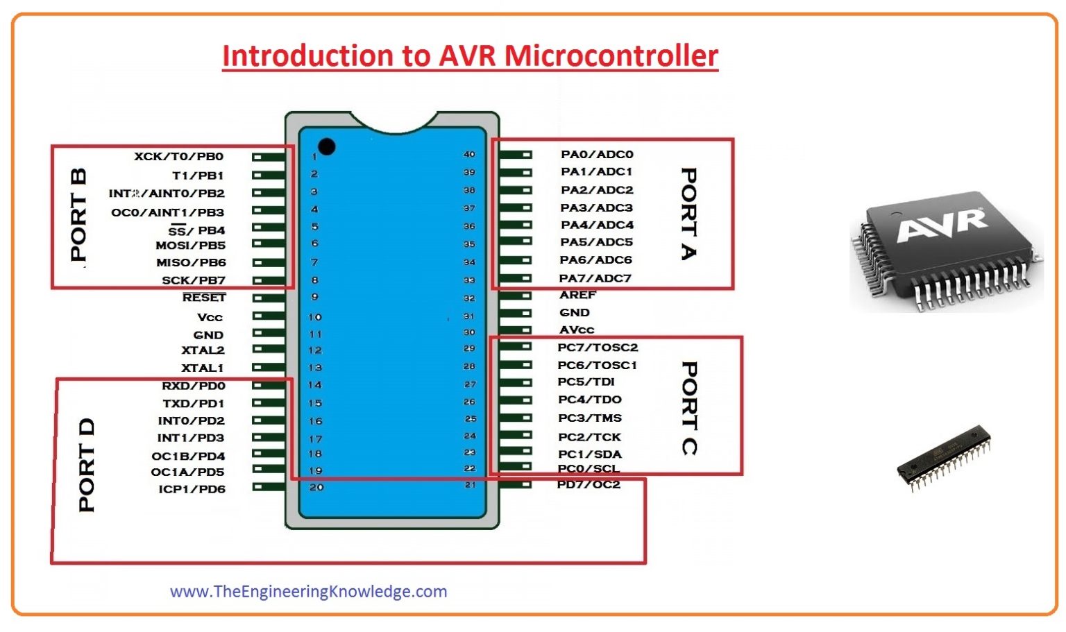
PIN CONFIGURATION
Pin description
There are 14 pins on this chip
- VCC- Supply Volatge
- GND- Ground
- PortA: (PA7:PA0) Port A is a 8-bit bi-directional I/O port with internal pull-up resistors (selected for each bit)Port A has alternate functions as analog inputs for the ADC, analog comparator, timer/counter, SPI and pin change interrupt.
- Port B: (PB3:PB0) Port B is a 4-bit bi-directional I/O port with internal pull-up resistors (selected for each bit).
- RESET: PB3 reset pin can also be used as a (weak) I/O pin.
ATtiny44 Microcontroller uses Harvard Architecture.
ESP-WROOM-32 Datasheet.
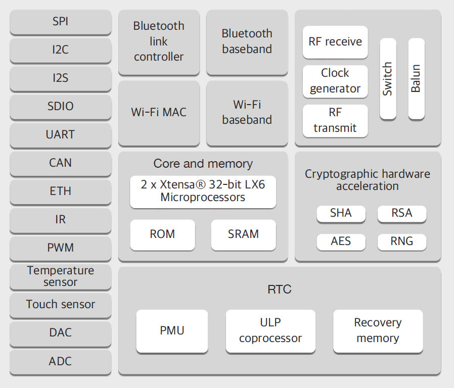
ESP-WROOM 32 is a dual core, 32-bit microcontroller module that is a part of ESP 32 series. Each CPU cores can be individually controlled. It can support clock frequency upto 240MHz and it has multiple power modes. The device has intergrated WiFi, Bluetooth and bluetooth low energy(BLE). The ESP32 has multiple digital and analog I/O pins and is one of the ESP32 series of microcontrollers.
The module is manufactured by Espressif systems in Shanghai and it is the successor to the popular esp8266. This device has upto eighteen 12-bit AD converters. There are also two 8-bit digital to analog converters, it has ten capacitive touch sensor inputs, four spi bus channels, two i2C bus connections and two i2s connections. (This is the bus that can carry audio). The device also contains three UARTS for serial communications. The esp32 can act as SD card host controller as well as host controller for other external devices like EMMC. It can be IR remote controller with upto eight individual channels. It can supplu pulse width modulation for driving motors as well as PMW for LEDs and there are upto 16 independent channels. It has an integrated Hall effect sensor and ultra low-power analog preamp and has multiple real time clock.
ESP32 BLOCK DIAGRAM
PIN CONFIGURATION
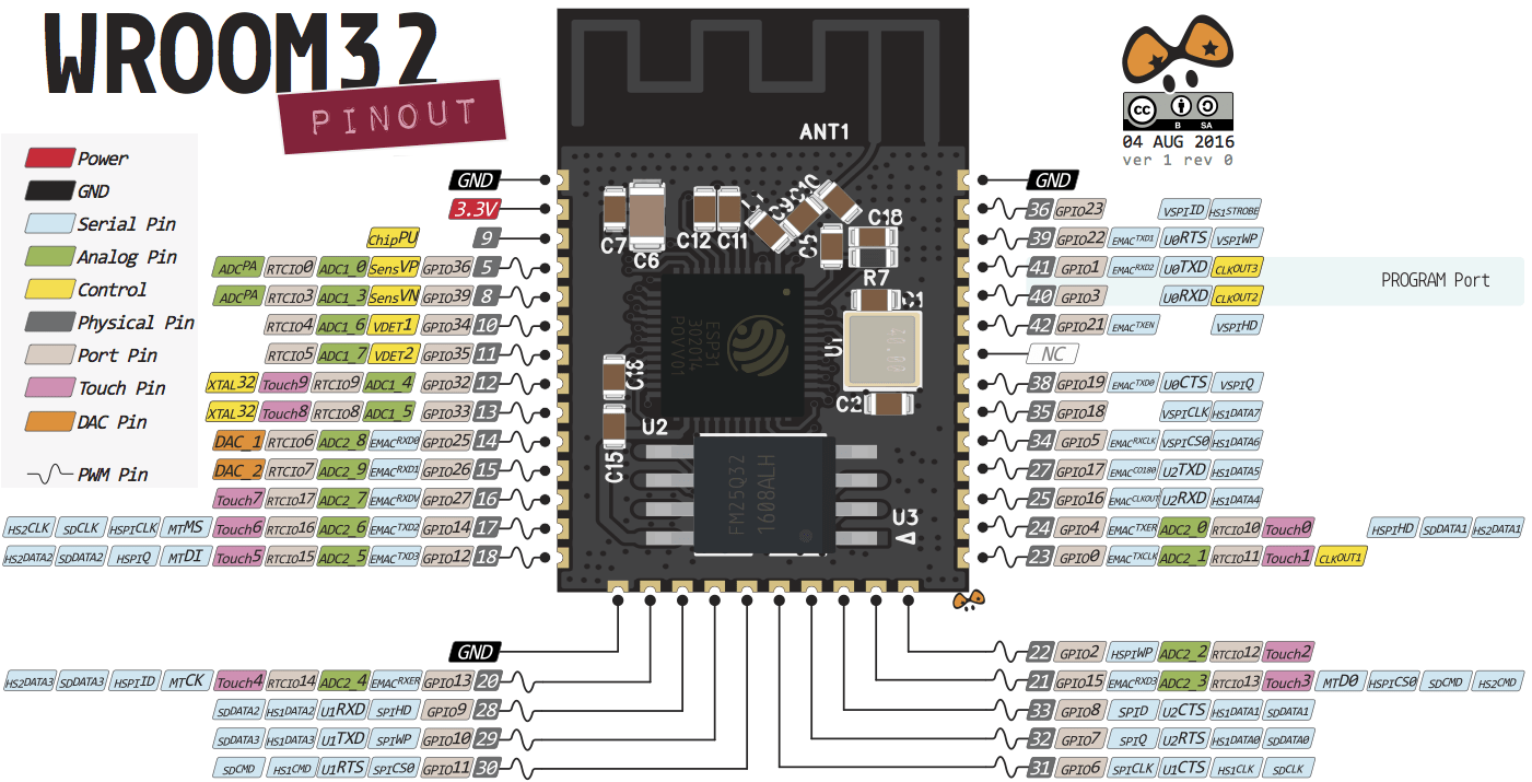
Pin Description
for pin description refer datasheet here
Programming with Arduino IDE
Arduino IDE
The Arduino IDE (Integrated Development Environment) is an open-source software, which is used to write and upload code to the Arduino boards. The IDE application is suitable for different operating systems such as Windows, Mac OS, and Linux. It supports the programming languages C and C++.
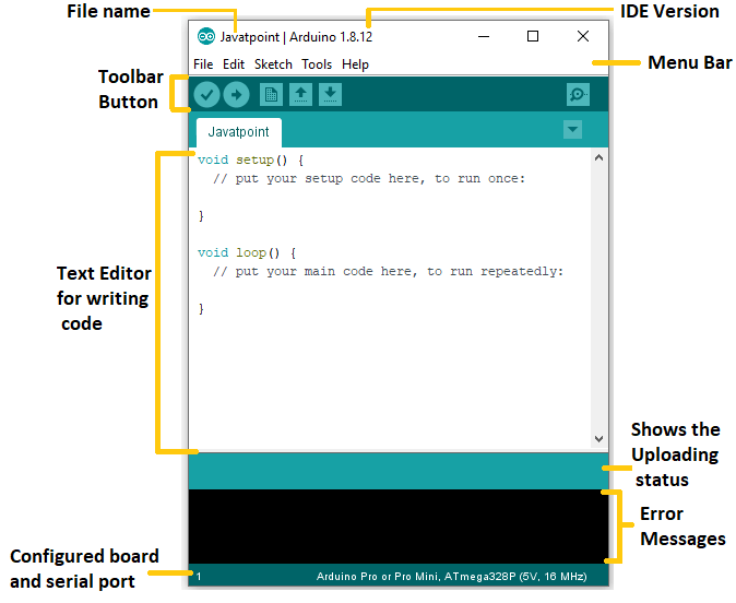
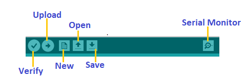
Toolbar Button
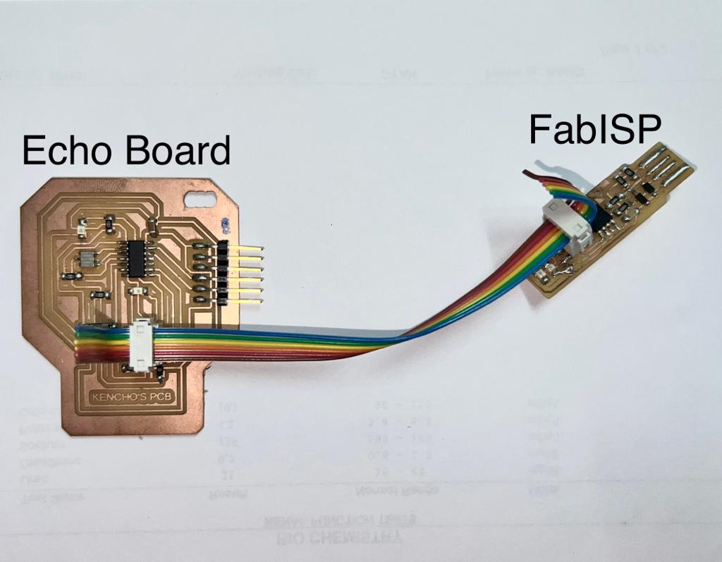
Steps to be followed to programme the Hello World board. For programming my helloworld board I have used my Fabisp which was already programmed in Electronic production week
Before you start programming make sure you install Arduino IDE, USB driver and Arduino ISP.
You can install Adafruit(USB driver) from here.
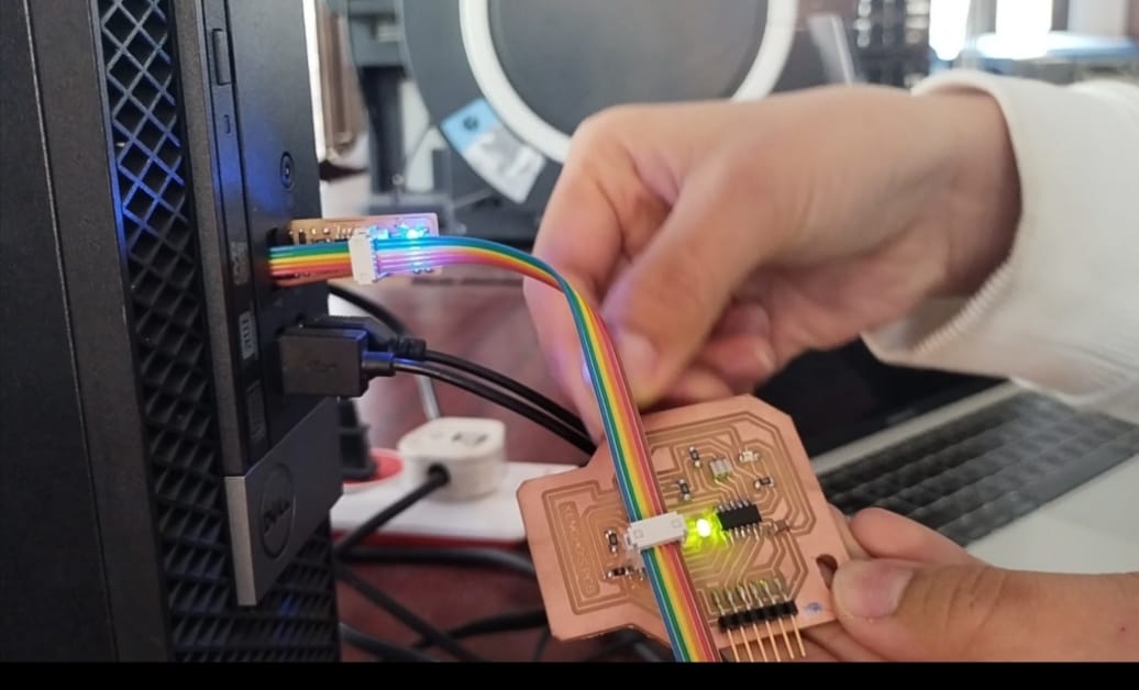
Then Connect your helloworld board to Fabisp and connect it to the computer.
Now make your Arduino IDE ready by following the steps mentioned below.
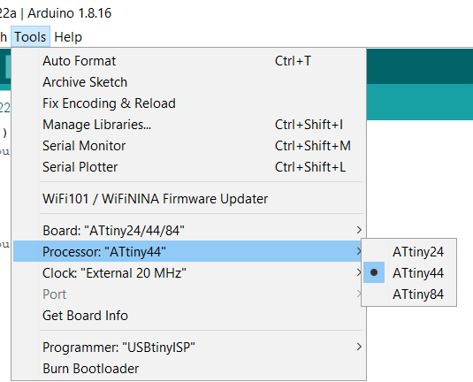
Now open the arduinoIDE software> Tools> Boards> Boards Manager> ATtiny Microcontrollers> ATtiny24/44/84
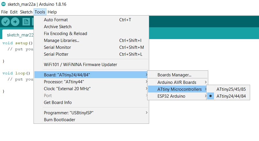
Tools> Processor> ATtiny44
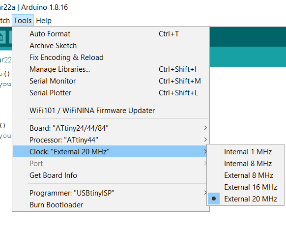
Tools> Clock> External 20 MHz
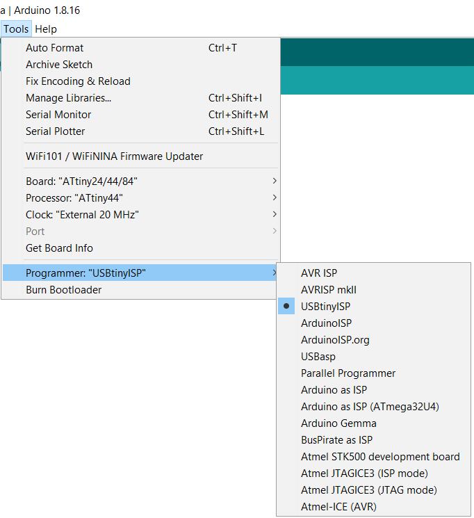
Tools> Programmer> USBtinyISP
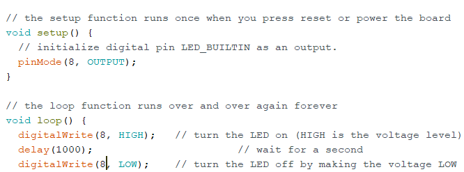
LED Blink Code
File> Examples> Basics> Blink
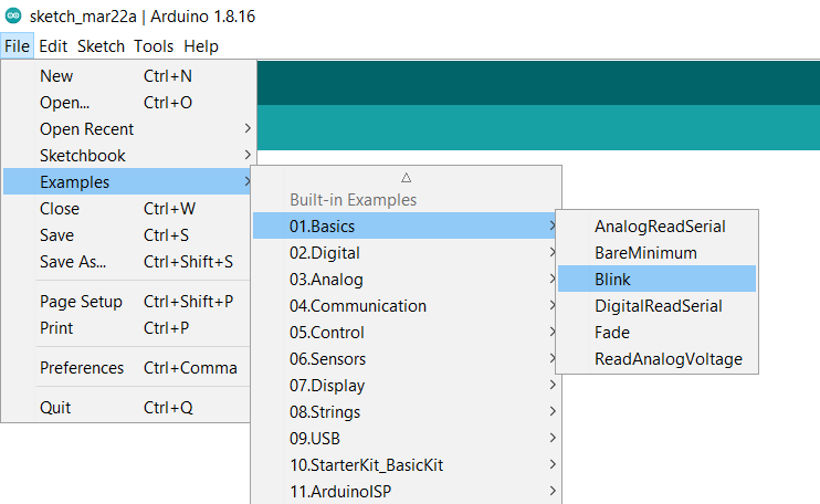 A new window will be created with the basic code to make led blink. You just have to change the pin mode according the mc pinout.
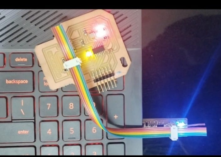
RESULT
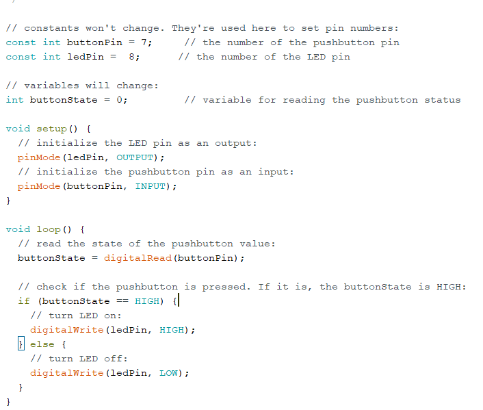
Push Button as input program
File> Examples> Digital> Switch
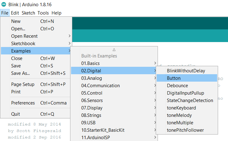
Again a new window will be created with basic code for blinking the led with switch.
Video Result
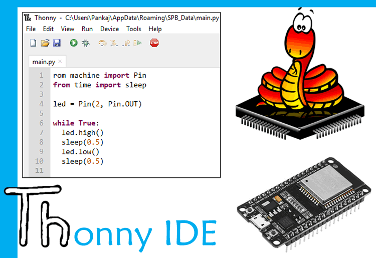
Programming with MicroPython
MicroPython is a lean and efficient implementation of the Python 3 programming language that includes a small subset of the Python standard library and is optimised to run on microcontrollers and in constrained environments.
setting up microPython environment to work with ESP 32.
For that first you have to download Thonypython IDE from Thonny.org. Since I am using windows I will be downloading the windows version and it’s also compatible for mac and linux.
Download MicroPython from here
Then download the micropythone firmware from micropython.org according to the board you are using.
Download the firmware from here
Next you have to download a ESP32 Usb driver if you are using Esp32 like me. You can download it fro silicon labs website
OR
Clickhere to download the firmware.
Once all the softwares were downloaded, install them to a folder of your chice.
Now open the Thonny Ide and code editor on your laptop to flas the esp with firmware.
For that click on the Tools menu in the tony python and go to manage plugins.
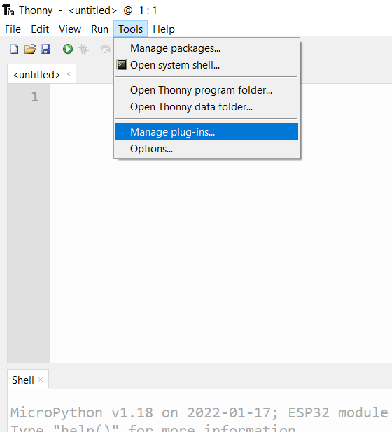
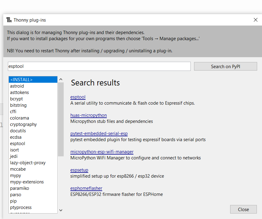
Then in the search box type esptool and install it.
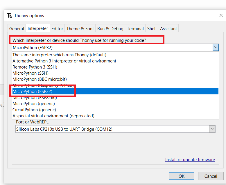
Once the esptool is installed, go to Tools menu and click on options and select interpreter.
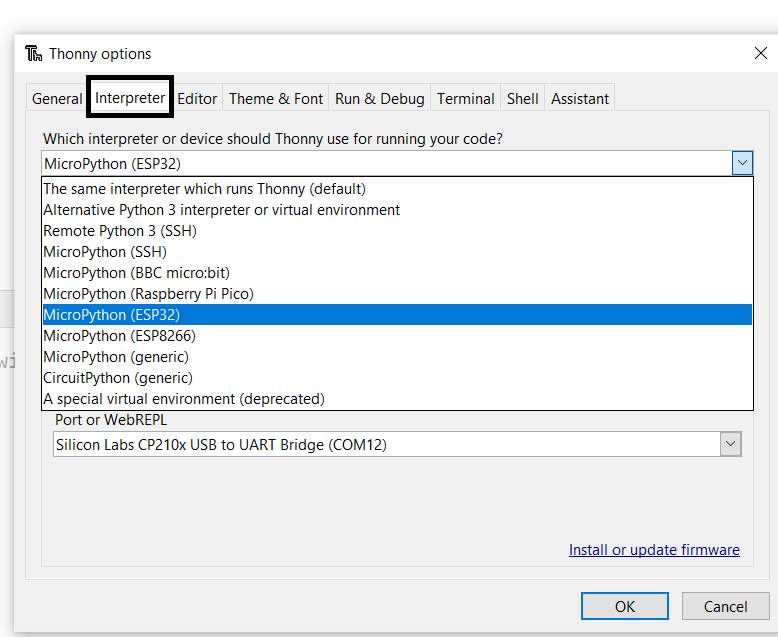
Then there is a question asking which interpreter or device should Thonny use for runnung your code? for that select MicroPython (ESP32) if you are using esp32 like me or select the interpreter you are using.
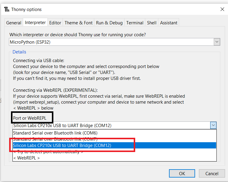
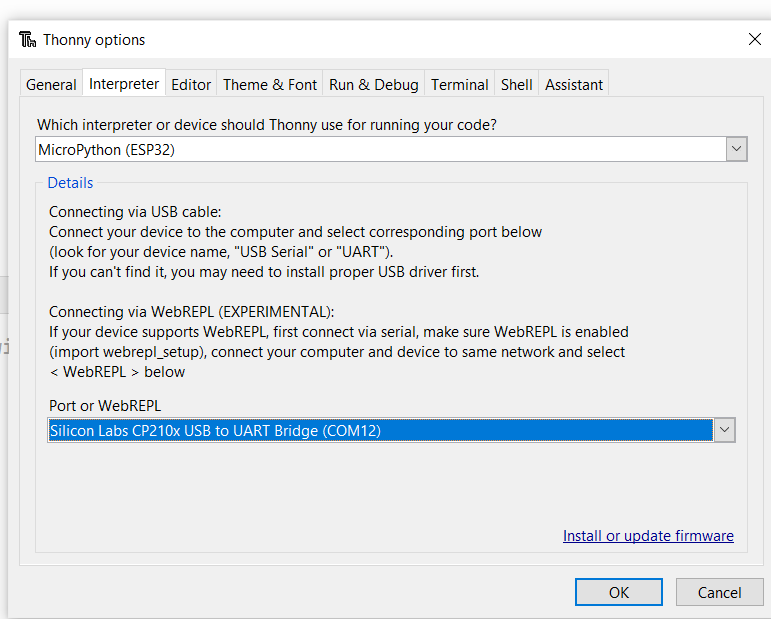
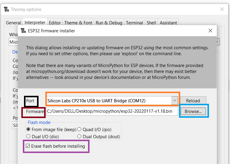
And in the Port select the correct port com. In my case my device is connected to com12.
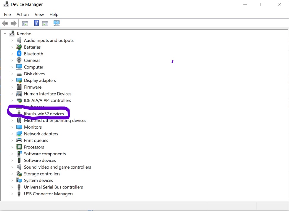
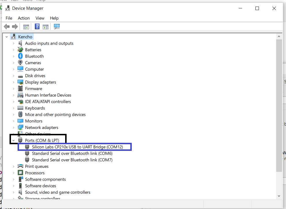
If you don’t know which port com is your decive connected, go to device manager and go to port and see which is the right port for your device.
Then on the same page there is a link asking to install or update firmware.
Click on it and a new page will pop up. Select the same port and to add firmware click on browse and add the esp32 firmware that was downloaded earlier.
Make sure the erase flash before installing box was ticked.
Now the micropython is sucessfully installed with esp32 development board.
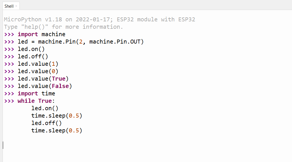
code
Let’s blink the inbuilt led on the ESP32 Board. Copy the code below and press enter twice.
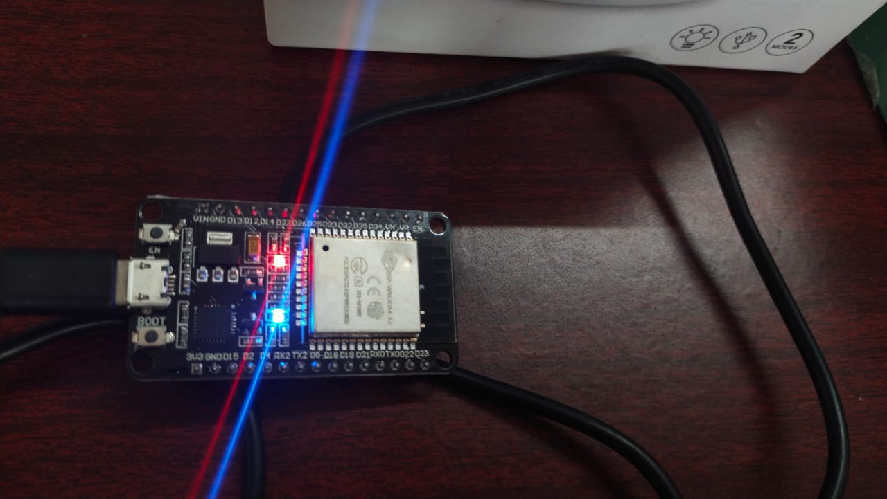
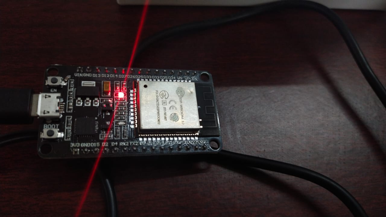
Result
Learning Outcome
- Learnt how to read datasheet for different microcontroller
- Explpored more about arduino programming
- Introduced to micropython
VIDEO