Final Project
Plan and sketch a potential final project
During my Pre Fab academy I have pitched few ideas about my final project. This week I finalized my project with my mentor and started to document what I have learnt from my week 1.
MY ROUGH PROJECT SKETCH
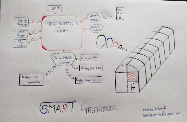
Why smart greenhouse?
The main reason why I came up with this project idea was because I wanted to convert all the greenhouse which are present at the mega farm in my institute into a smart one. There are more than 50 greenhouses which are currently being opperated mannually. First I will build a small prototype in my Fab academy course and once I graduate from fab academy I will apply the same concept at a larger scale in our Fablab. After that, I will integrate it within my college farm. I have dotted more reasons for coming up with the idea about smart greenhouse in the following words.
General Objective
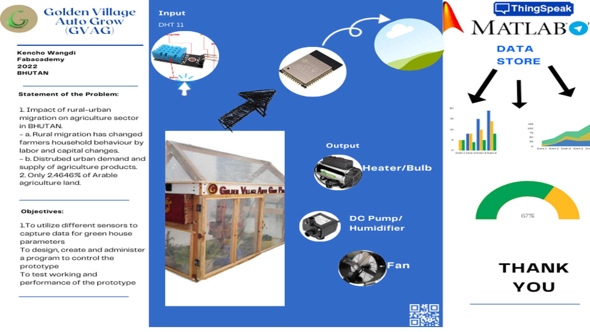
The general objective of this project is to design, fabricate and implement a microcontroller based prototype to monitor and control greenhouse parameters using sensors, SMS technology and Bluetooth signals.
Specific Objectives
The specific objectives were:
- i. To utilize different sensors to capture data for green house parameters,
- ii. To interface sensors, LCD, wifi and Bluetooth to the ATmega328, ESP 32 microcontroller,
- iii. To design, create and administer a program to control the prototype,
- iv. To test working and performance of the prototype.
Statement of the Problem:
1. Impact of rural-urban migration on agriculture sector in BHUTAN.
- a. Rural migration has changed farmers household behaviour by labor and capital changes.
- b. Distrubed urban demand and supply of agriculture products.
2. Only 2.14646% of Arable land.
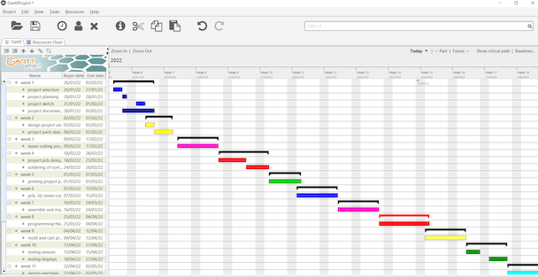
GanttProject Chart
I will do all my small project task according to fab academy assignments and hope to complet it on time. Here is my ganntproject chart.
SOME CHANGES FOR THE FINAL PROJECT
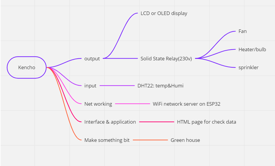
Initailly I thought of using 4 input device and 5 output devices.
After discussing with my remote mentor Takesen and Rico, we decided to use only 2 input devices and 4 output devices.
The input devices that I will be using are: 1. Temperature sensor 2. Humidity sensors 3. OR DHT 11 sensors.
The output devices used will be: 1. DC motor for fan- to cool down the temperature 2. Bulb/ heater- to increase the temperature incase of temperature drop. 3. H2O sprinkler- to increase the humidity. 4. OLED- to dispaly the data.
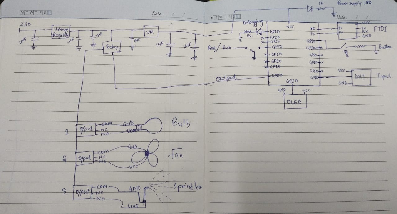
ROUGH CIRCUIT DIAGRAM
Detail of My Final Project
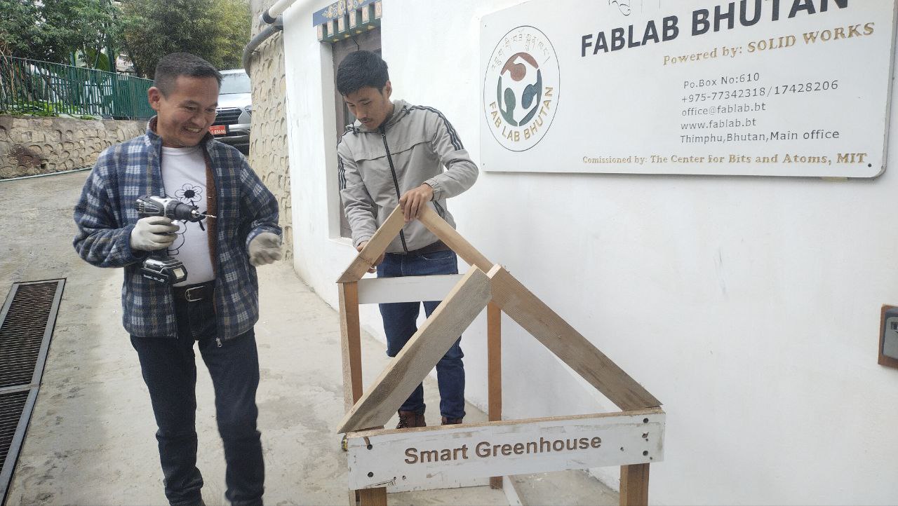
From the begining of the fabacademy I been thinking of making a portable greenhouse so that after I finished my course I can take it with me to my college. For that I have used a light material which is easily available and inexpensive.
There are lots of unused wooden planks and plyboard all around our fablab. I collected some of them and stored inside the lab so that once I finished my designing I will cut them as per my design.
Other Materials required for the Greenhouse
- Temperatur sensors
- Humidity sensors oR
- DHT 11/ DHT22 sensor
- Light bulb/ Heater
- DC Fan
- DC pump
- Humidifier
- Wire
- Relay Switch.
- polyethylene plastic.
- OLED for display
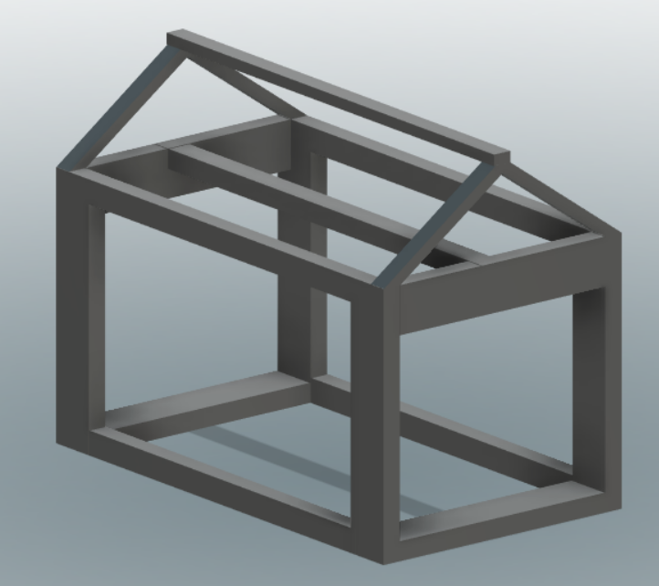
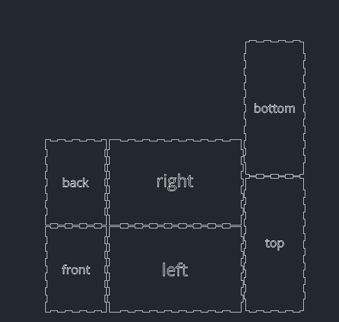
DESIGNING
Idea to Sketch I have used fusion 360 to design almost everything for my project.
skeleton of the greenhouse
Microcontroller and relay case
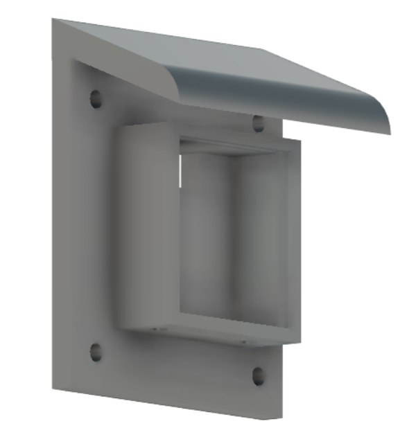
Case for the OLED I made a case for the OLED as it was going to placed on the door or near the distribution box. I made a small roof to protect the led from rain and made a provision for a glass cover.
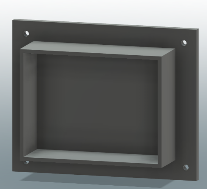
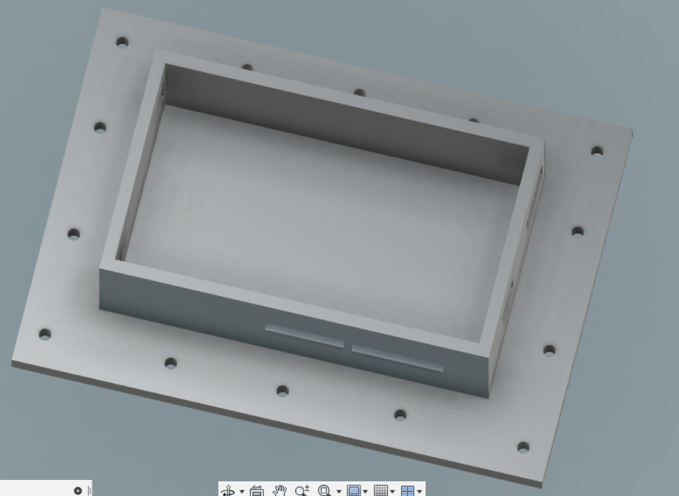
Distribution board I made a distribution board to hold all the power supply and microcontroller board to protect them from rain and to make it look tidy.
ELETRONICS
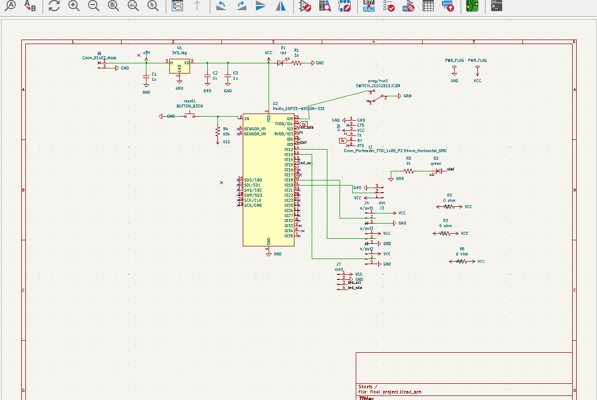
Previously I used EAGLE to make PCB design during electronic design and electronic production week. Later I switched to KICAD to design my PCB boards as KiCad is an open source and much easier for me to use.
schematic Design I have used 3.3V 1A Voltage regulator to cut down the incoming voltage and a program run switch. I used a reset button, a power led and a reset led. I have used 4 output pins and a input pin of the ESP WROOM32 Microcontroller. I have used the sdl and scl pin of the controller for the oled. aAs i ma going to use FTDI to programme my board I have used the TX and RX pin of the microcontroller as sown in the schematic.
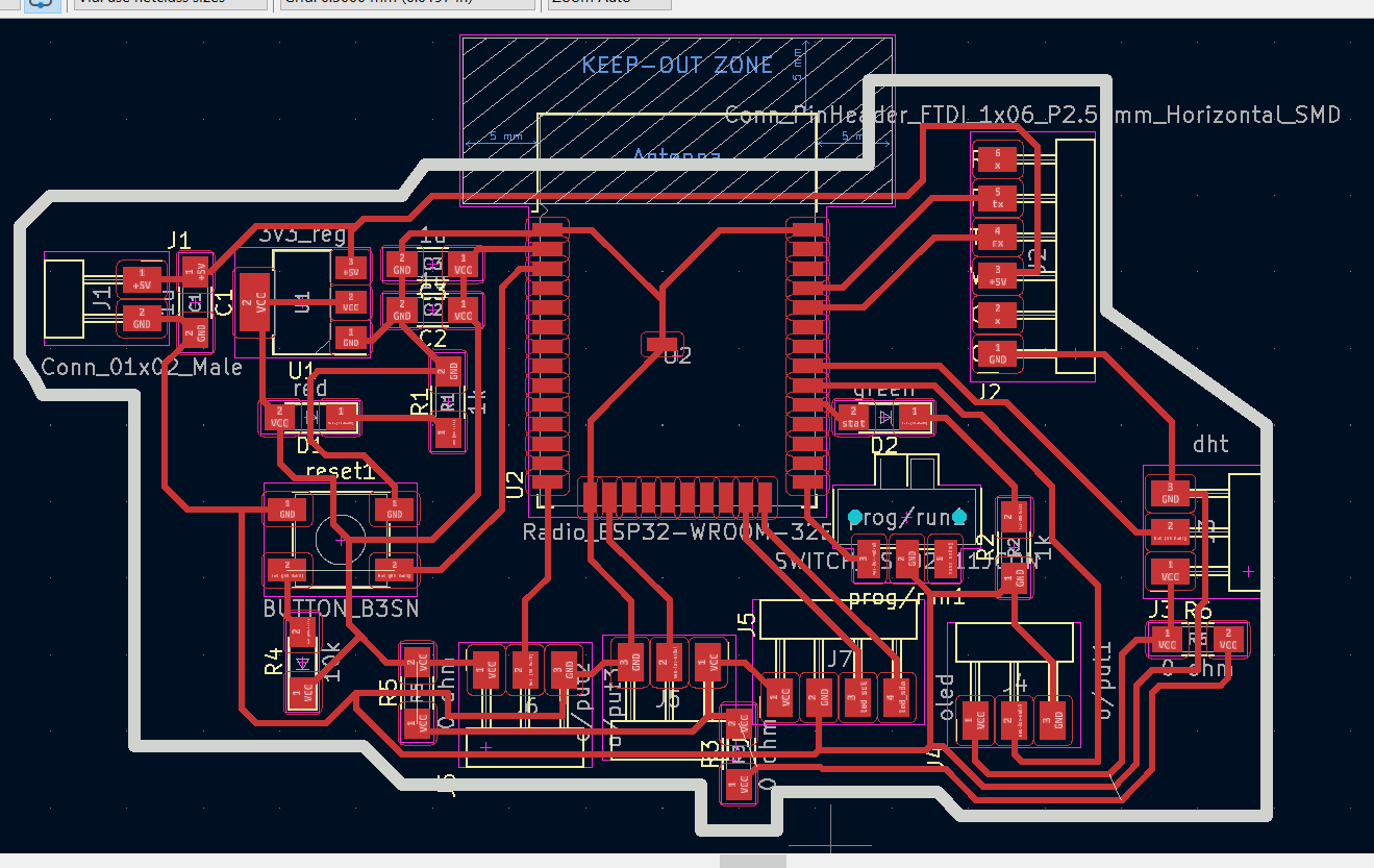
Board Design
Once I finished the schematic I assigned the footprints and routed according to the schematic. I used Inspect dropdown menu to check any errors in my board.
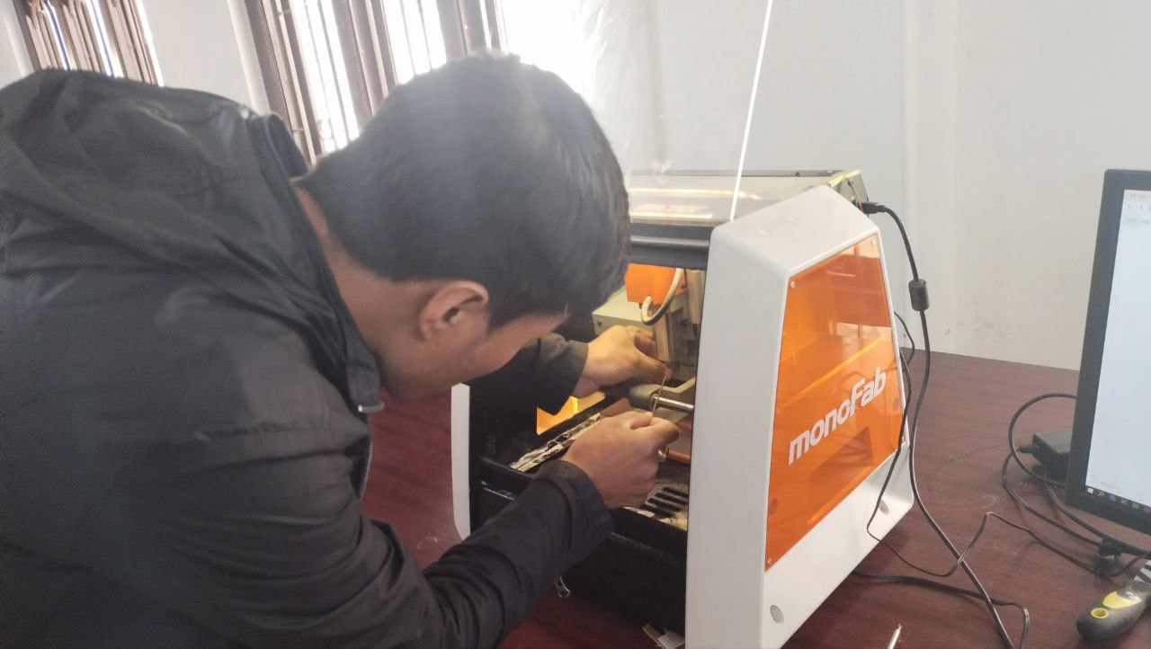
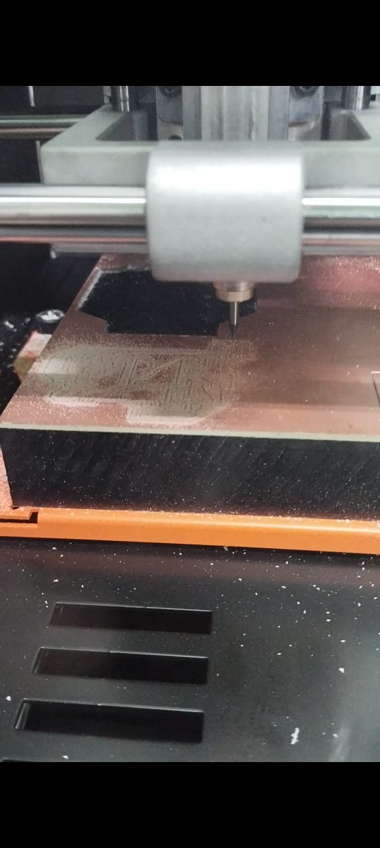
Milling of the board using SRM20
Once the board was ready, it was time for milling. I have used 1/64 to route the traces and 1/32 to cut the edge.
Soldering of the components. Once the board was milled I soldered the components.
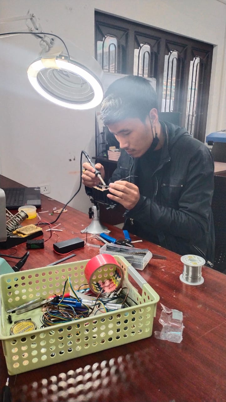
SOLDERED BOARD
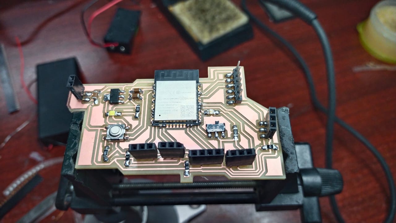
After soldering I did a quick test using multimeter and found that everything was fine.
CIRCUIT CONNECTIONS
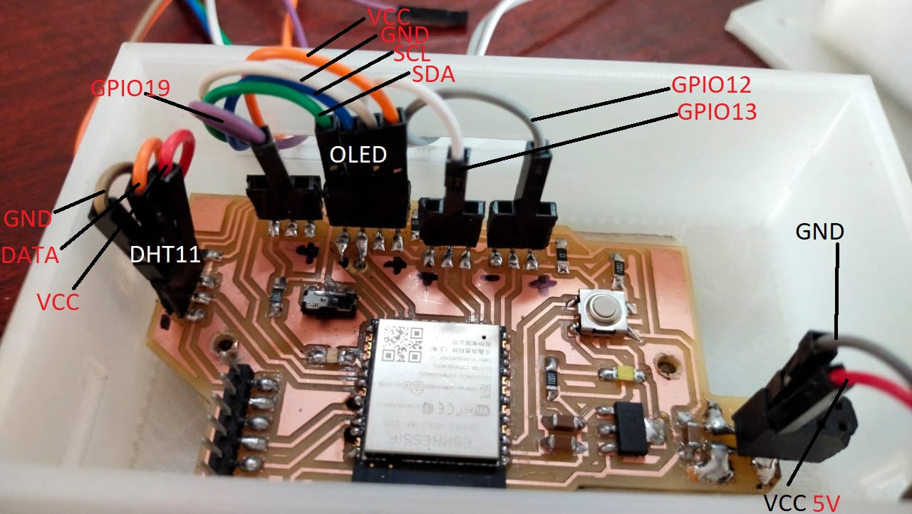
Before I jumped onto the coding part I completed all the circuit connection.
Different color of jumper wires were used and all of them were labeled so that it doesn’t create any confusion if you are making a similar project.
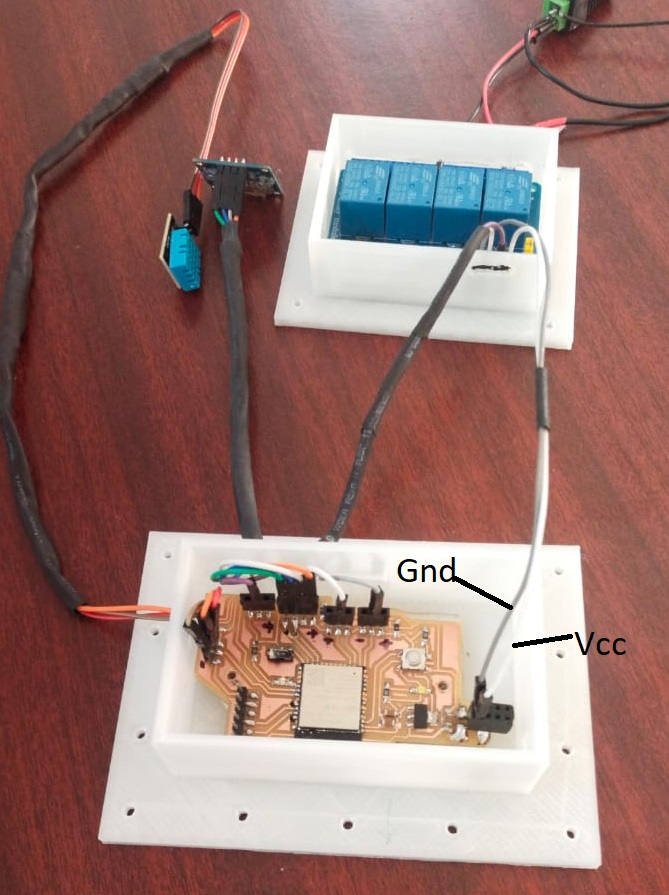
Board to relay connections.
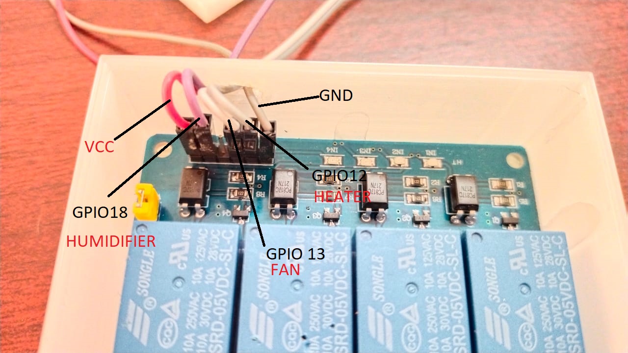
Complete circuit connection between controller board and rely.
In this image I have used white and grey jumper wire for Vcc and Gnd. to clear the confusion white one is Vcc and the grey one is Gnd. Others all are same as shown in the above circuit diagram.
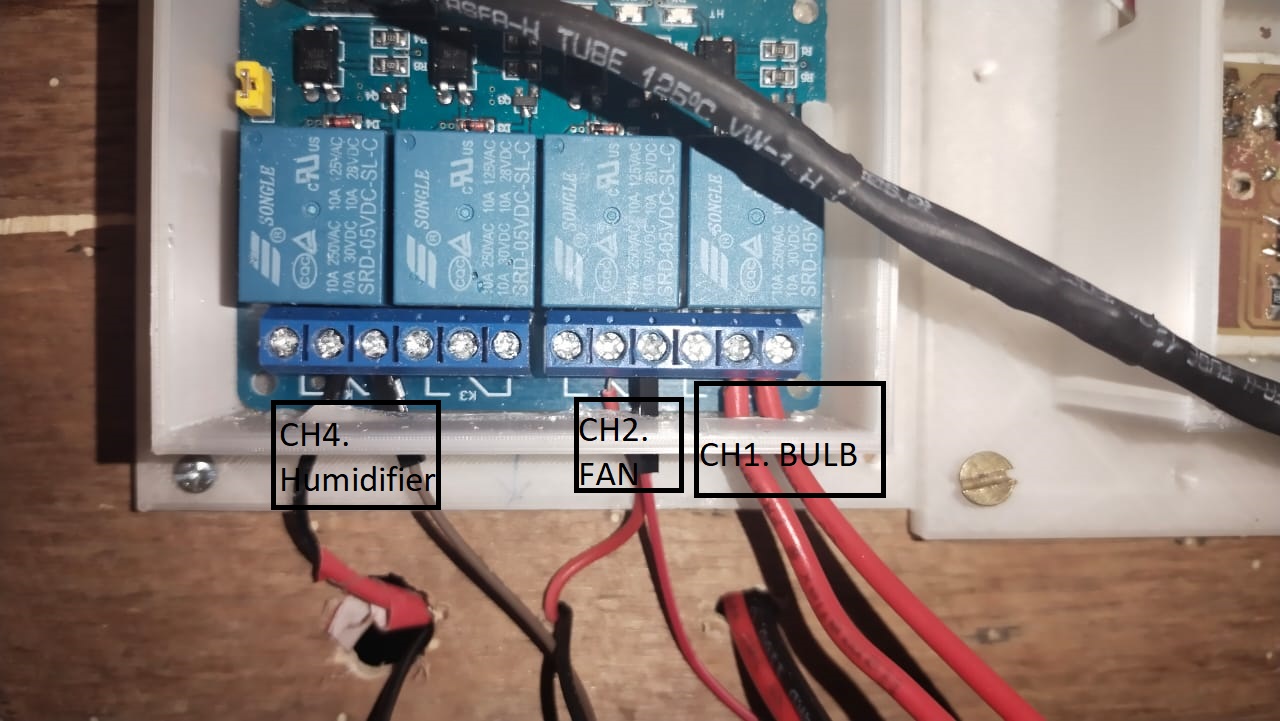
Relay to the output connection
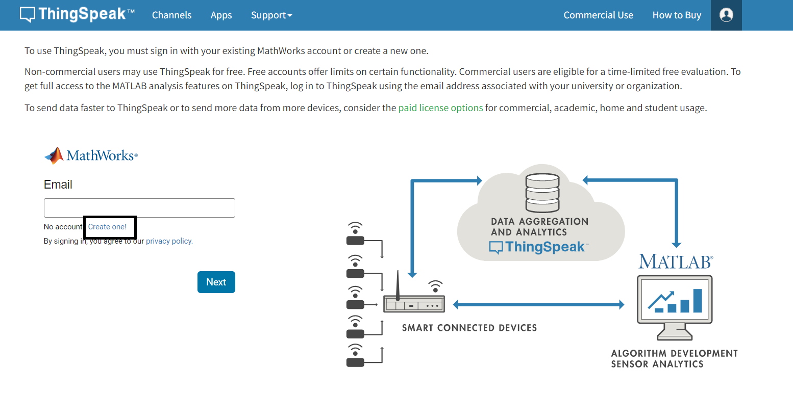
Creating Thingspeak Account
To create thingspeak account, go to thinspeak.com and click on singup button. Punch in your email address and a password.
Then click on New channel to create yor channel.
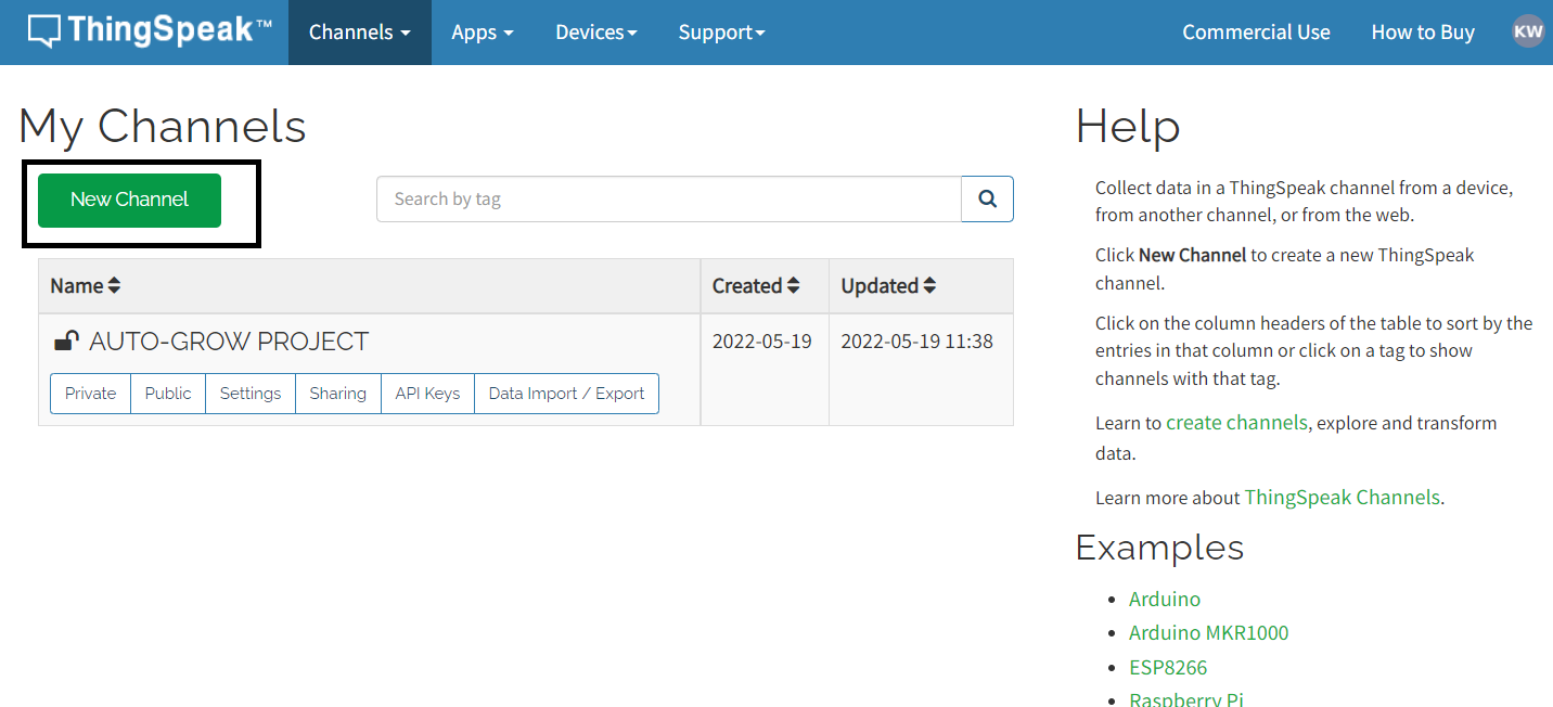
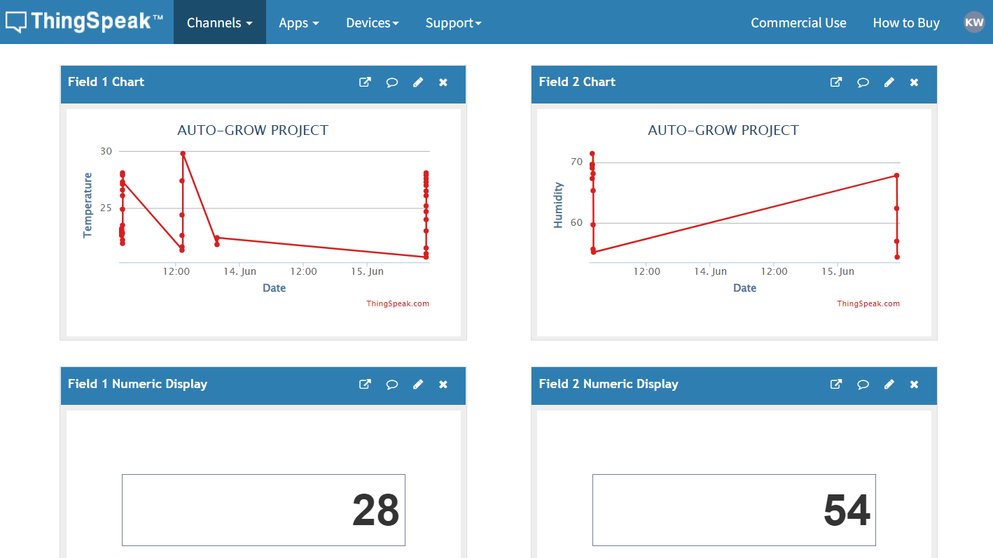
Once the channel is created insert the channel Id and API keys in your code and your dashboard should look like this.
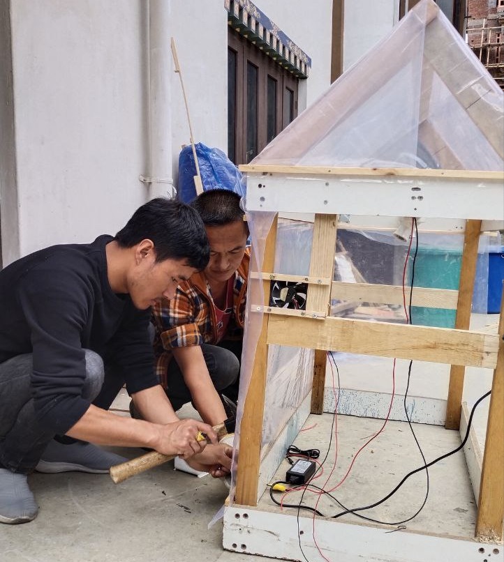
Making of a fountain to balance the humidity.
For the humidity I made a fountain using the bamboo cane. I used table saw to cut the bamboo as per my design.
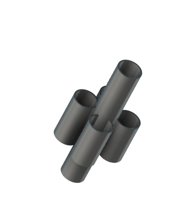
Final product
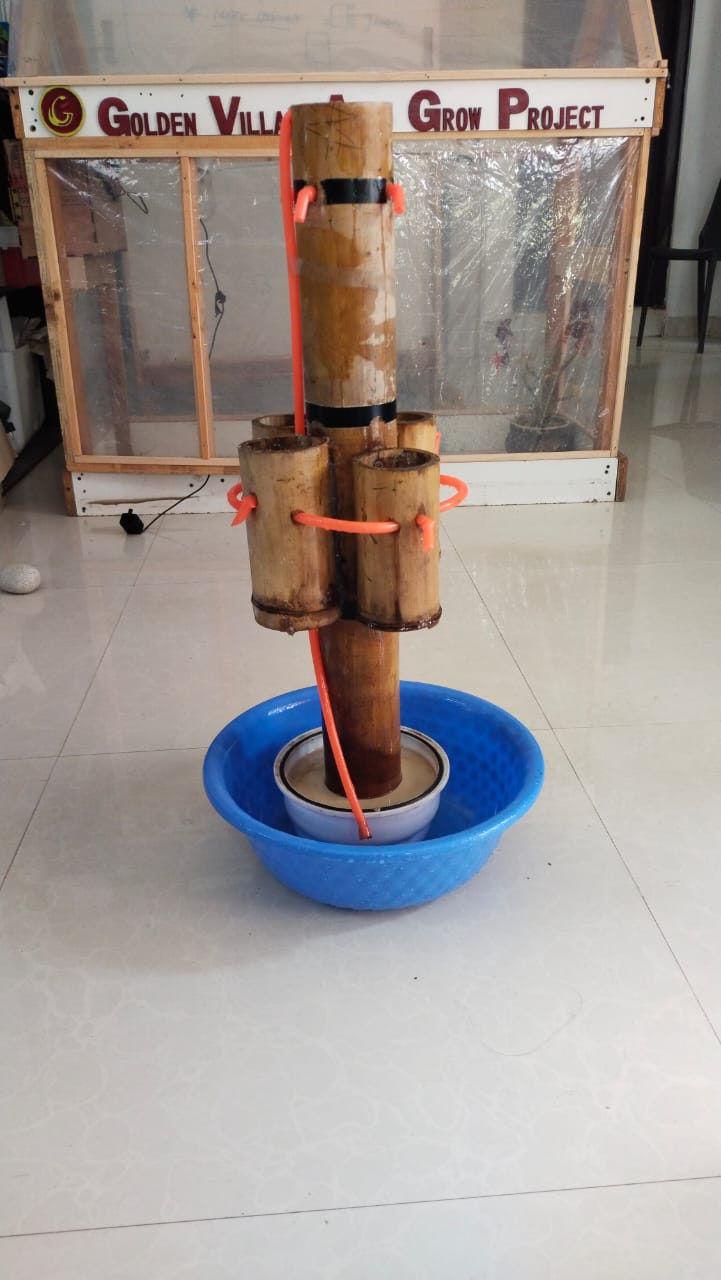
I use 12V submersible DC pump for the fountain.
Testing of the 12V DC pump
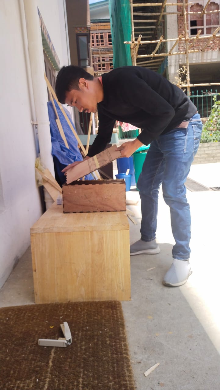
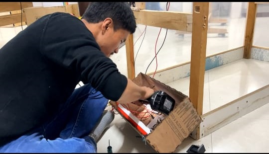
Making distribution box and microcontroller case
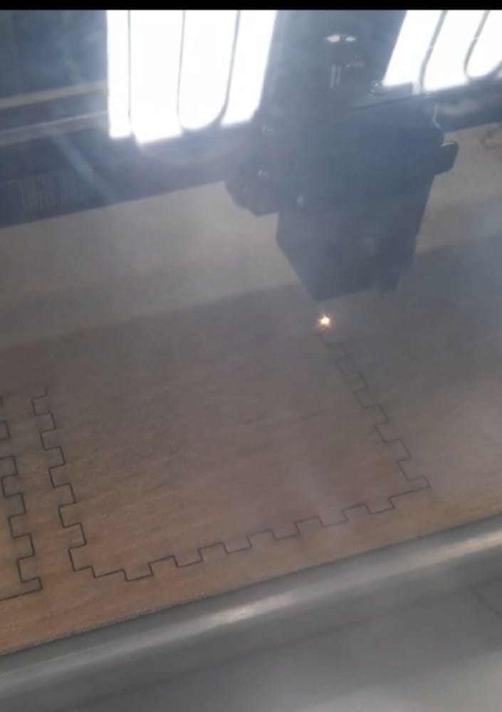
The design of the distribution board was cut using laser cutter and was assembled.
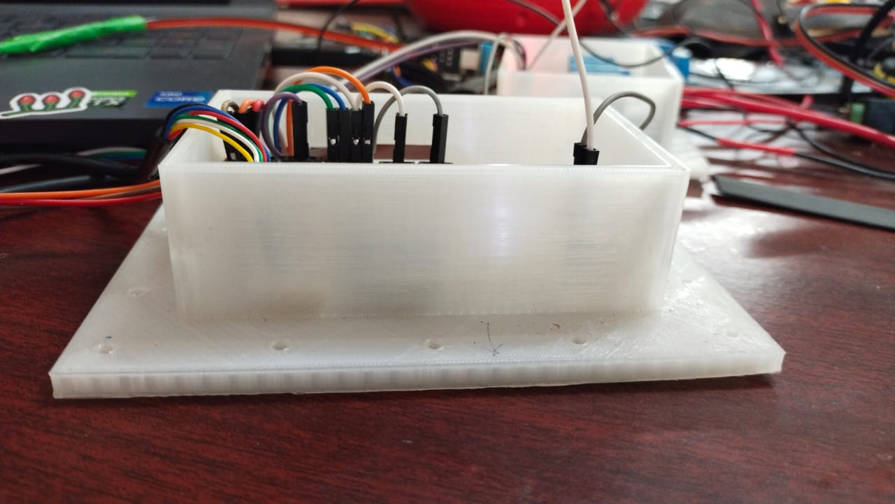
The design of the microcontroller case was printed using 3D printer.
CODING
Once all the above process were done I did the coding part.
#include "DHT.h"
#include <WiFi.h>
#include "ThingSpeak.h"
#define DHT11Pin 19
#define DHTType DHT11
//OLED
#include <Wire.h>
#include <Adafruit_GFX.h>
#include <Adafruit_SSD1306.h>

DHT HT(DHT11Pin,DHTType);
float humi;
float tempC;
float tempF;

const char* ssid = "dd-wrt_vap";   // your network SSID (name)
const char* password = "fab172030!";   // your network password

unsigned long onTime = 1000;
unsigned long offTime = 1000;

unsigned long previousMillis=0;

// Interval is how long we wait
int interval = onTime;

// Used to track if LED should be on or off
boolean state = true;


//OLED define
#define SCREEN_WIDTH 128 // OLED display width, in pixels
#define SCREEN_HEIGHT 64 // OLED display height, in pixels
// Declaration for an SSD1306 display connected to I2C (SDA, SCL pins)
Adafruit_SSD1306 display(SCREEN_WIDTH, SCREEN_HEIGHT, &Wire, -1);
WiFiClient client;
unsigned long myChannelNumber = 1740990;
const char * myWriteAPIKey = "T0PLONIHX01RJ9TI";

void setup() {
    pinMode(12,OUTPUT);
    pinMode(13,OUTPUT);
    pinMode(18,OUTPUT);
    Serial.begin(9600);
  //For DHT11
  HT.begin();
  WiFi.mode(WIFI_STA);
  ThingSpeak.begin(client);


  //For OLED I2C
  if(!display.begin(SSD1306_SWITCHCAPVCC, 0x3C)) { // Address 0x3D for 128x64
    Serial.println(F("SSD1306 allocation failed"));
    for(;;);
  }
  display.display(); //Display logo
  delay(1000);
  display.clearDisplay();
}

void loop() {
 delay(1000);
 humi = HT.readHumidity();
 tempC = HT.readTemperature();
 tempF = HT.readTemperature(true);
 Serial.println(humi);

 if(WiFi.status() != WL_CONNECTED){
      Serial.print("Attempting to connect");
      while(WiFi.status() != WL_CONNECTED){
        WiFi.begin(ssid, password);
        delay(5000);
      }
      Serial.println("\nConnected.");
    }
 int x = ThingSpeak.writeField(myChannelNumber, 1, tempC, myWriteAPIKey);
 int y = ThingSpeak.writeField(myChannelNumber, 2, humi, myWriteAPIKey);

 display.clearDisplay();
 oledDisplayHeader();
 oledDisplay(3,5,28,humi,"%");
 oledDisplay(2,70,16,tempC,"C");
 oledDisplay(2,70,44,tempF,"F");

 display.display();
 digitalWrite(18,state);
 unsigned long currentMillis = millis();

if( tempC<25 )  // 12=Light Bulb , 13= FAN , 18=Humdifier
  {
    digitalWrite(12,LOW);
  }
else
  {
    digitalWrite(12,HIGH);

  }

if( tempC>30 )  // 12=Light Bulb , 13= FAN , 18=Humdifier
  {
    digitalWrite(13,LOW);
  }
else
  {
    digitalWrite(13,HIGH);
  }
label:
if( humi<70 )
  {

   if ((unsigned long)(currentMillis - previousMillis) >= interval) {
      // Change wait interval, based on current LED state
      if (state) {
         interval = offTime;
      } else {
         interval = onTime;
      }
      state = !(state);
      previousMillis = currentMillis;
   }
  }
else{
    digitalWrite(18,HIGH);


  }

}
void oledDisplayHeader(){
 display.setTextSize(1);
 display.setTextColor(WHITE);
 display.setCursor(0, 0);
 display.print("Humidity");
 display.setCursor(60, 0);
 display.print("Temperature");
}
void oledDisplay(int size, int x,int y, float value, String unit){
 int charLen=12;
 int xo=x+charLen*3.2;
 int xunit=x+charLen*3.6;
 int xval = x;
 display.setTextSize(size);
 display.setTextColor(WHITE);

 if (unit=="%"){
   display.setCursor(x, y);
   display.print(value,0);
   display.print(unit);
 } else {
   if (value>99){
    xval=x;
   } else {
    xval=x+charLen;
   }
   display.setCursor(xval, y);
   display.print(value,0);
   display.drawCircle(xo, y+2, 2, WHITE);  // print degree symbols (  )
   display.setCursor(xunit, y);
   display.print(unit);
 }

}
Assembling all the parts together.
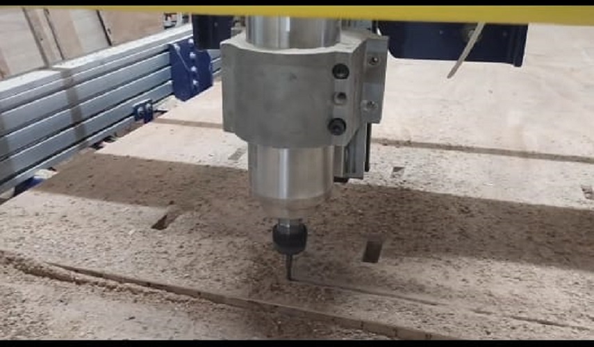
I started with assembling the skeleton of the greenhouse. The greenhouse parts were cut using shopbot.
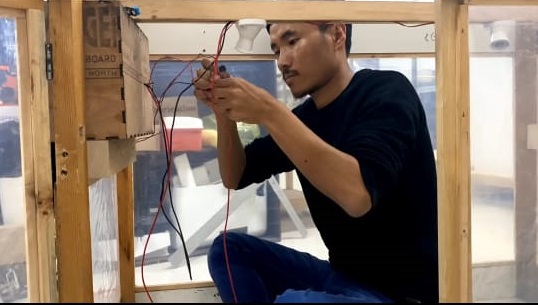
wiring
Before covering the greenhouse with plastic, I completed all the wiring which includes both inside and outside of the greenhouse.
Covering with Plastic
Once I finished wiring and erecting the structure I then Covered the greenhouse with plastic.
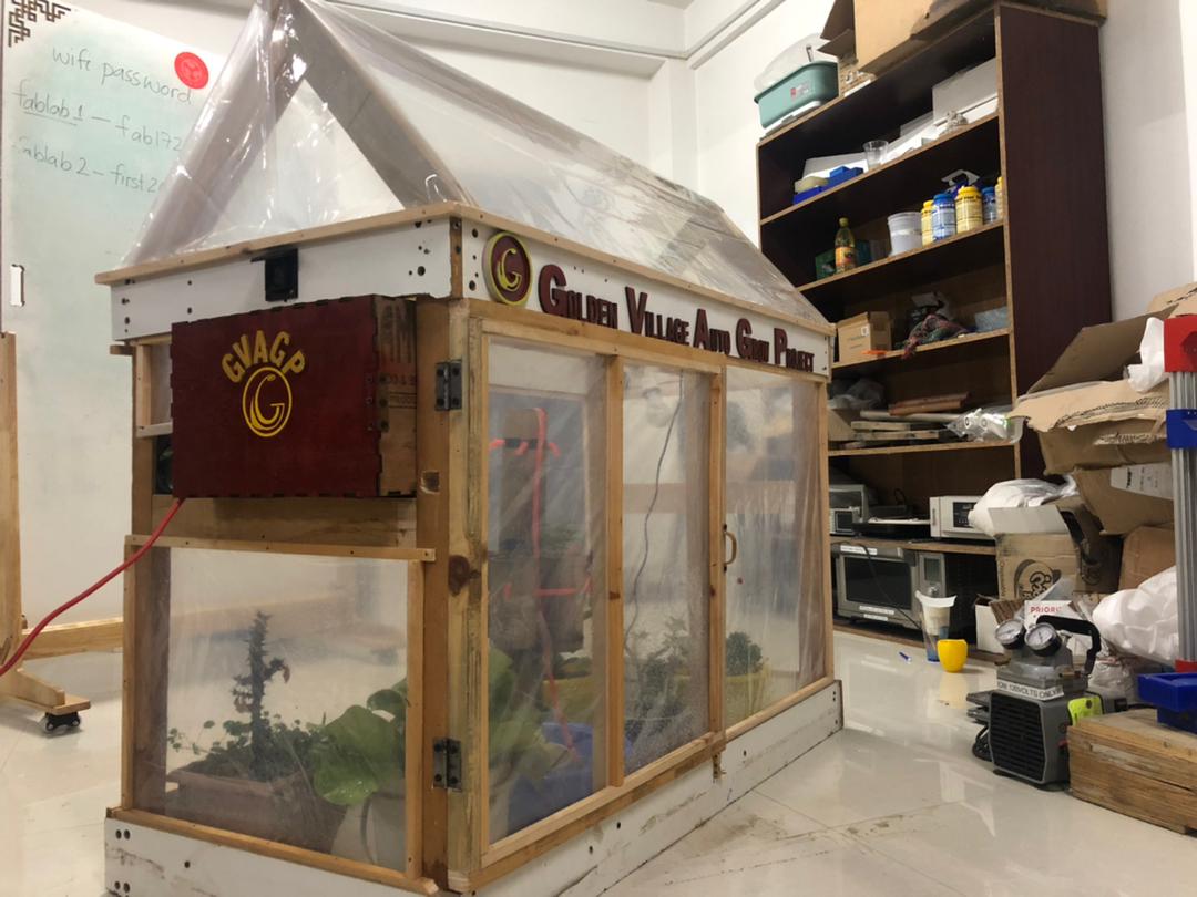
FINAL RESULT
The greenhouse was successfully completed.
Presentation.png
Presentation.mp4
Original Files
Download all the original files from here.