12. Output devices
Individual assignment:
Add an output device to a microcontroller board you’ve designed, and program it to do something.
Group Assignment: Measure the power consumption of an output device.
For the group assignment REFER HERE
For the Individual assignment I wanted to try all my output device for my final project but I couldn’t make it. I tested positive for covid and have to home quarantine for one week.
Actually I designed my ESP board for my final project when we went to setup fablab (CNR Biofab lab) at Punakha.
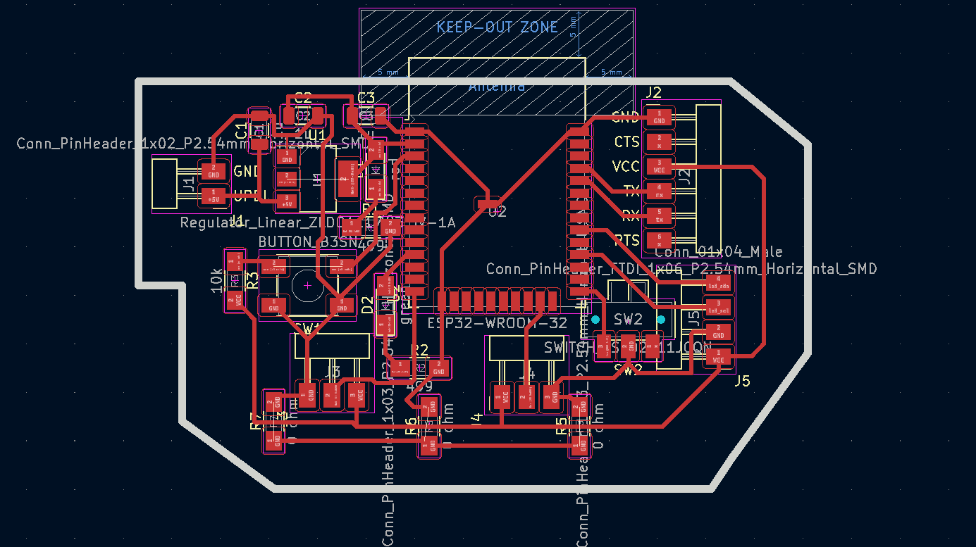
I used KiCAD to design my board.
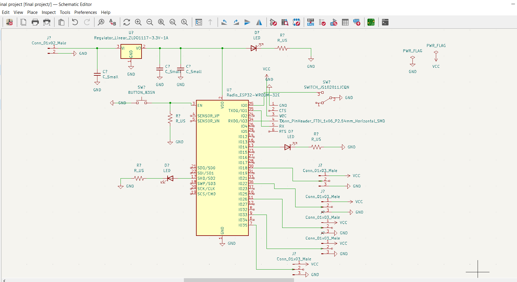
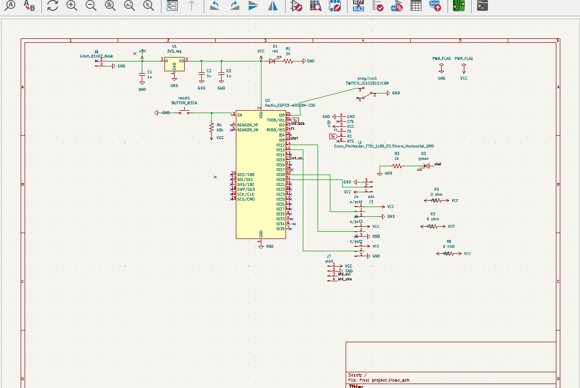
Here are my schematic and board design.
schematic design
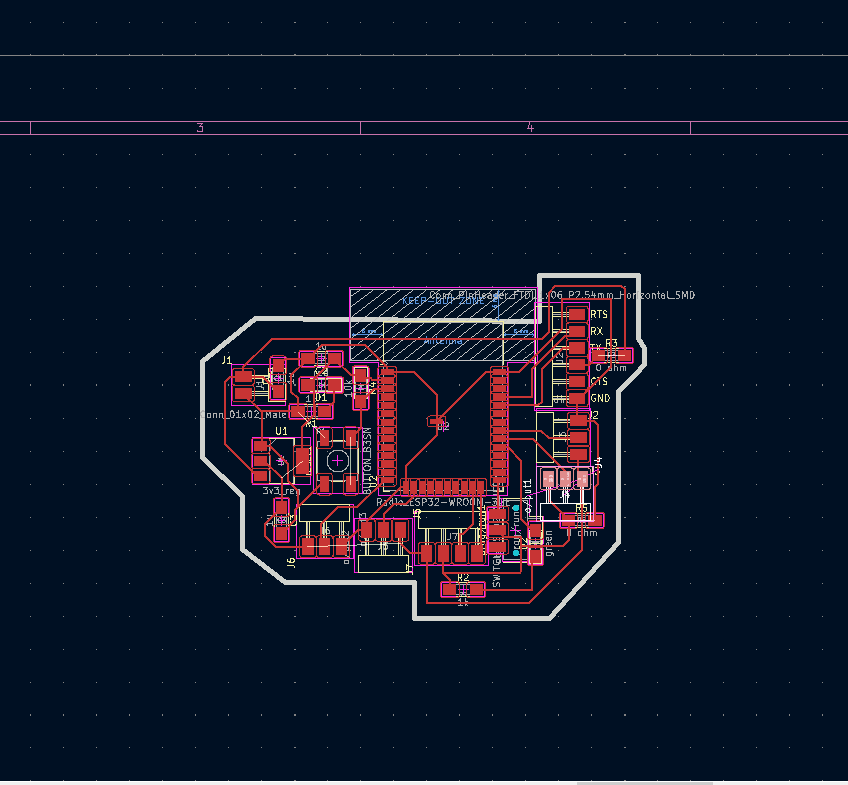
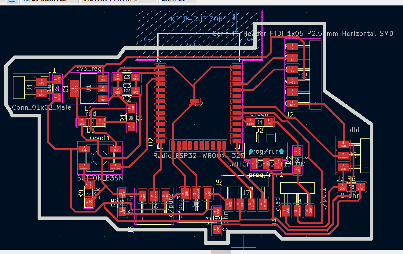
Board design
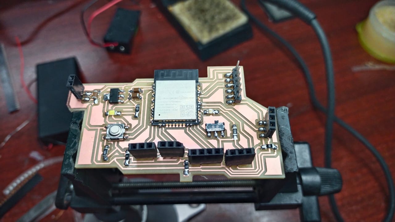
Then I used the newly installed SRM-20 to mill the board soldered all the components.
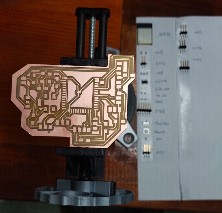
I used a 3.3v 1A voltage regulator to cut down the 5v power to 3.3v for the microcontroller, but somehow when I soldered the components, I shot circuited the traces which result in giving direct 5v power to esp32 and it burned the esp32 as shown below. At the same time there are few unconnected traces and non-functional led.
I decided to make a new controller board just for the output week.
Board design for the output week.
schematic Design.
Board Design.
Now my board is ready but the problem is I am still under home quarantine and couldn’t get access to lab. Meanwhile I will try to use ESP32 Uno board, to programme an output and later when I get access to lab I will mill my board to try different outputs.
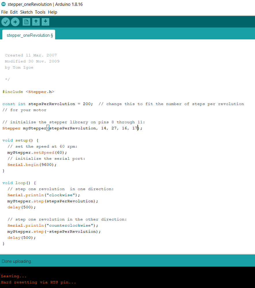
This time I am going to control a stepper motor using ESP board.
code
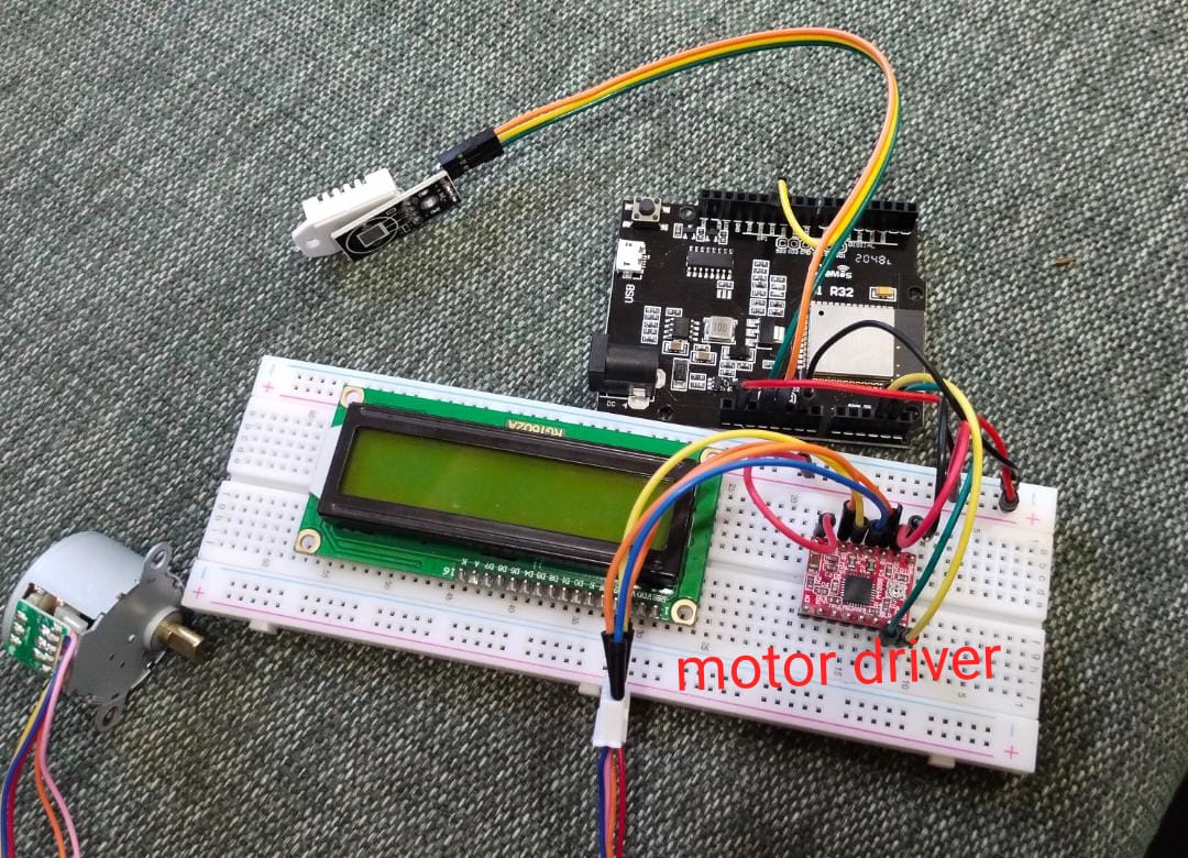
Circuit Connection
Initially I tried to use motor driver A4988 to drive my stepper motor. I connected the motor driver to a breadboard and gave the connection as per the pin out of the driver to esp32 uno and then to the stepper motor.
I connected two analog pin of esp32 uno to direction and step pin to the motor driver and A and B pin of driver to the motor. I connected the vcc to esp32 board and vmot to the common 5v power, thinking that the motor is 5v. After a successful connection I tried to program the motor using arduino ide but even after successful compiling and uploading the program the stepper motor is not spinning as per the program.
Then I realized that I need a new driver to drive the motor. So I used ULN 2003 motor driver. I made the connection as shown in the image below.
I edited the program and compiled again and uploaded it. Finally it worked.
Video
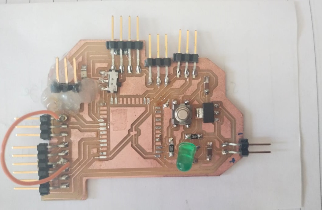
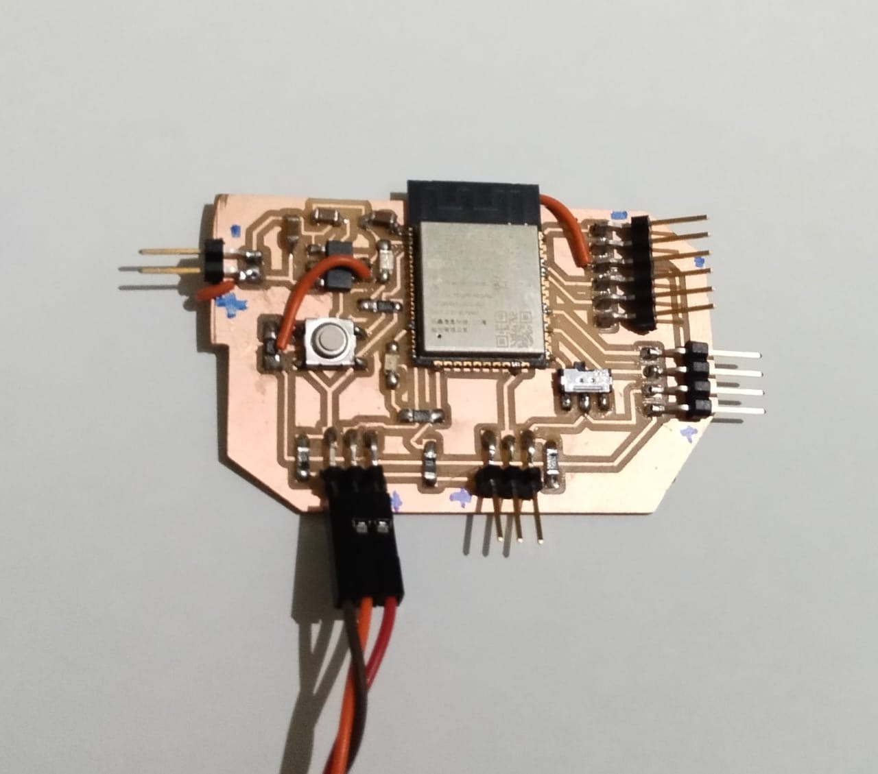
Once I reched the lab, I milled my board and soldered the components.
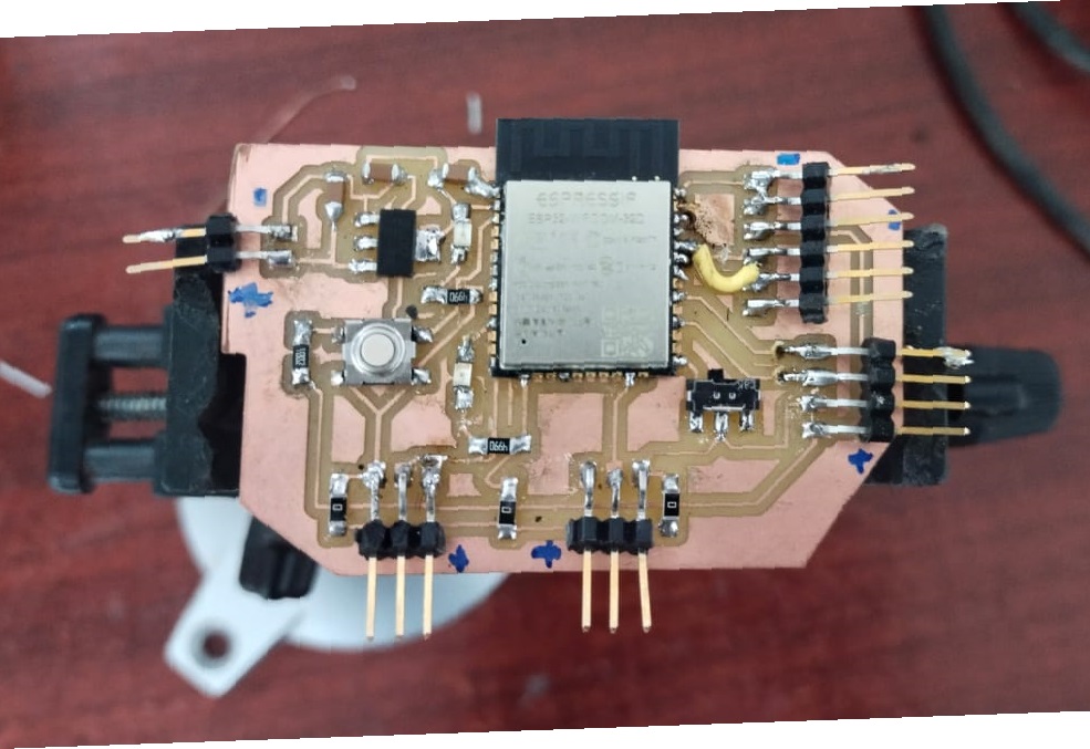
There are few mistakes while routing the board. For that I have used jumper wires to do the corrections. Once the correction was done I tested the board and it’s working fine. Next time I will make the necessary correction and milled the board for my final project.
Output device used for the week
- 12V Fan
- Oled
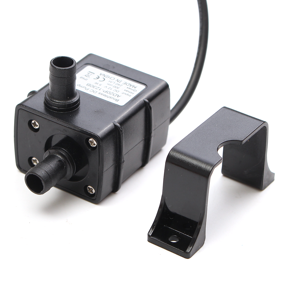
- 12V DC Pump
12V DC fan
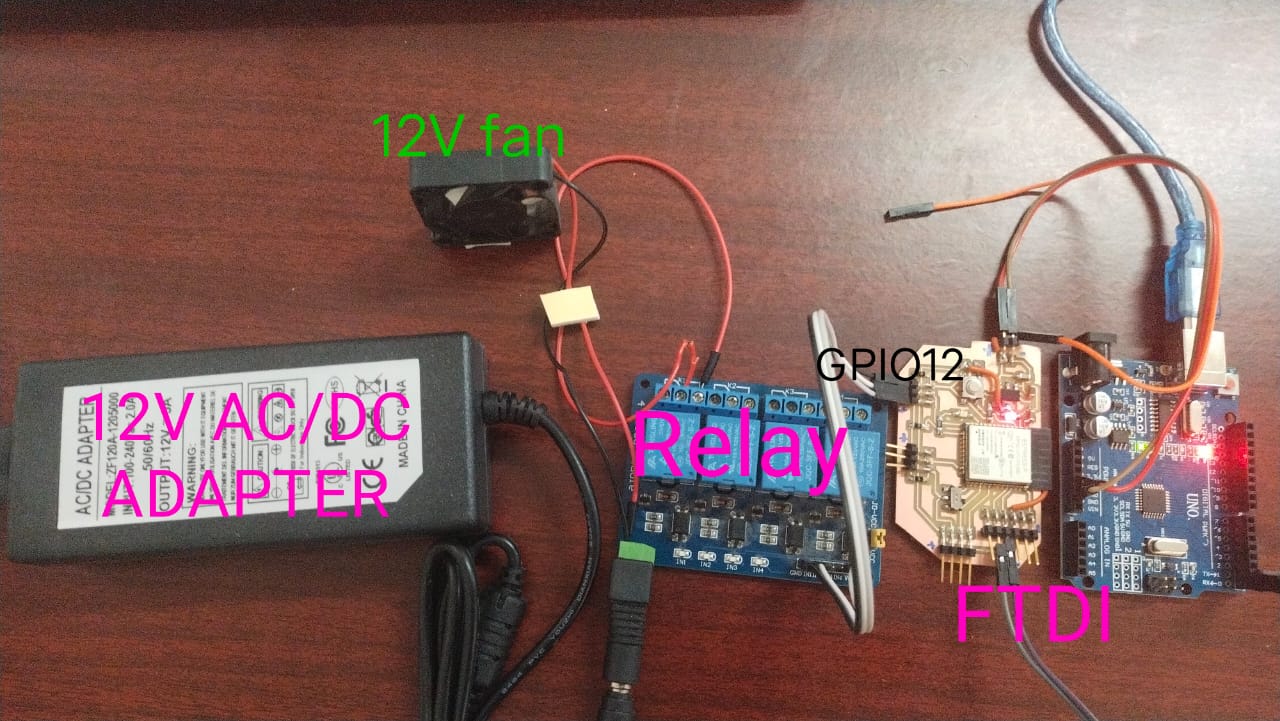
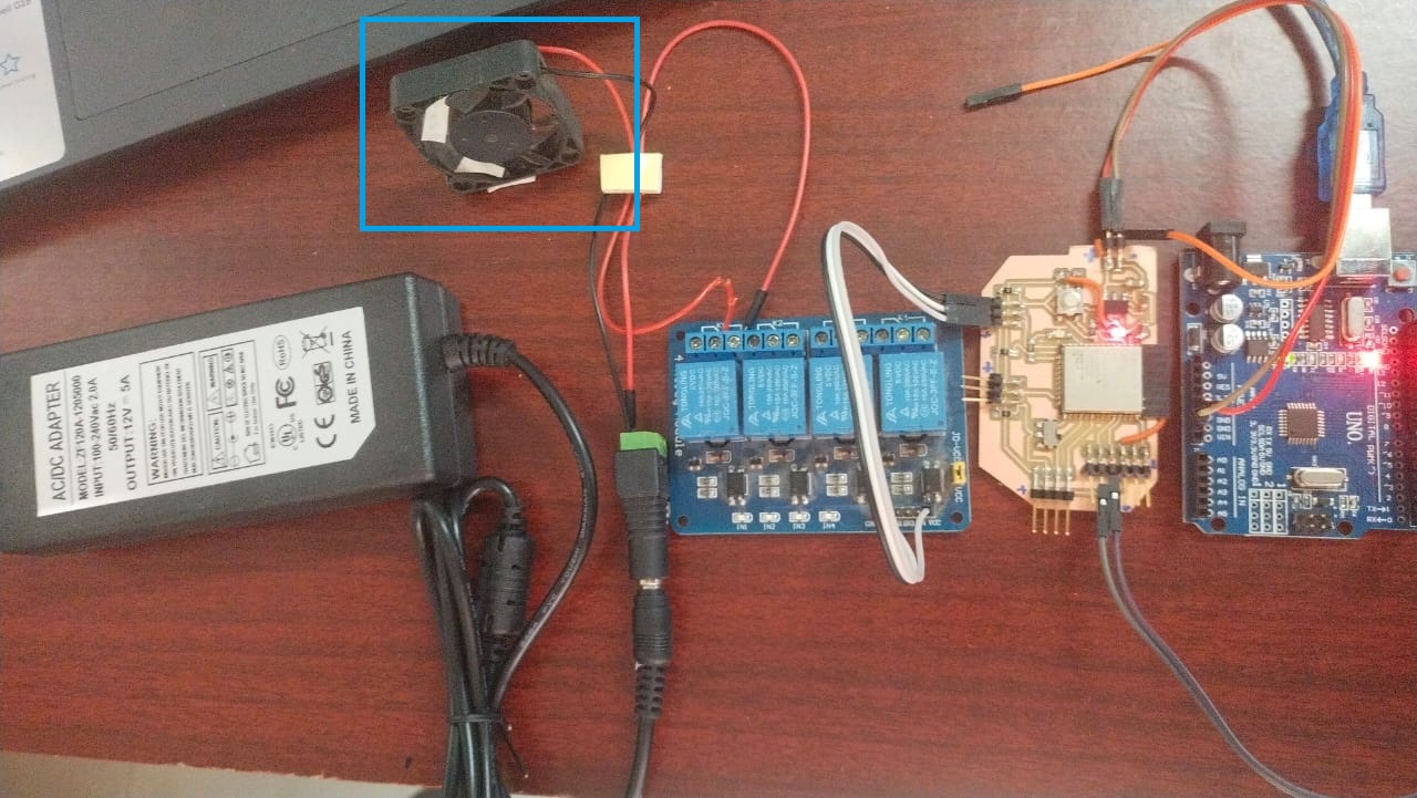
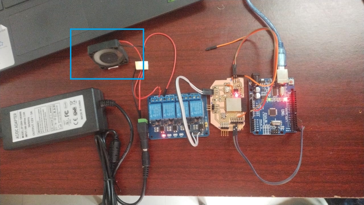
Hardware required. - ESP32 wroom32 board. - Arduino UNO - Relay - 12V cooling fan - 12V power adapter - jumper wires and USB - FTDI Cable
If I connect the 12V fan to a power supply of 12V, the fan spins at full speed. so, to control the speed of the fan I have used a relay. You can use FTDI cable to program the board directly but in my case I have used the TX and RX pin of arduino uno to run the program specifically for this output as I wanted to learn whether I can use arduino uno to program my board or not.
Wiring Diagram
code
/*
 * This ESP32 code is created by esp32io.com
 *
 * This ESP32 code is released in the public domain
 *
 * For more detail (instruction and wiring diagram), visit https://esp32io.com/tutorials/esp32-controls-fan
 */

#define RELAY_PIN  12  // ESP32 pin GIOP27, which connects to the IN pin of relay

// the code in setup function runs only one time when ESP32 starts
void setup() {
  // initialize digital pin A5 as an output.
  pinMode(RELAY_PIN, OUTPUT);
}

// the code in loop function is executed repeatedly infinitely
void loop() {
  digitalWrite(RELAY_PIN, HIGH); // turn on fan 10 seconds
  delay(10000);
  digitalWrite(RELAY_PIN, LOW);  // turn off fan 10 seconds
  delay(10000);
}
This code periodically turns the fan ON/OFF in every 10 seconds.
Result
Off for 10 seconds
On for 10 seconds
Initailly I tried DHT22 and a 12V dc fan for the output week as shown above. Later I did all the correction in the board design and milled a new board for my final project. Then I tried OLED and 12V DC pump using the final project board.
Final board schematic
Final board Design
Final Project soldered board
For detail refer my final project documentation.link
OLED as an output
Hardware required
- ESP32 Board.
- Oled
- FTDI Cable
- jumper wires and USB
Oled pin out
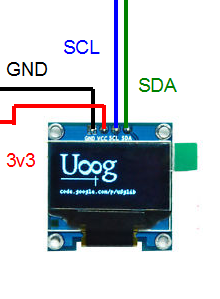
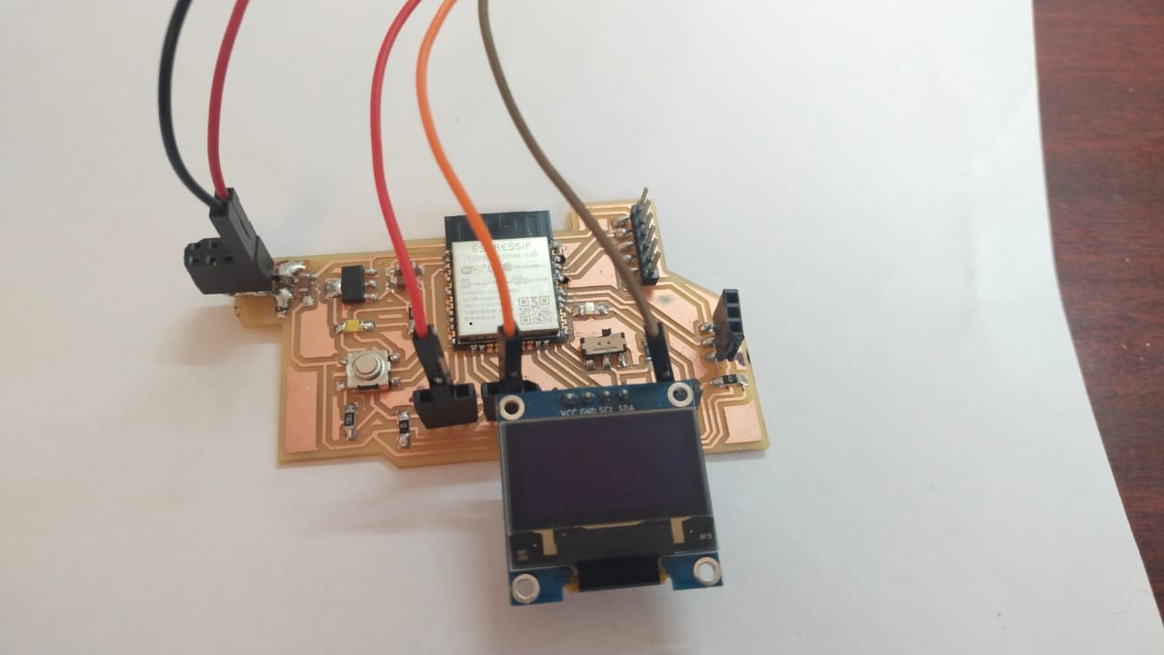
Circuit connection
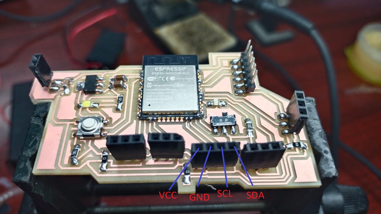
Now connect the Oled as per the pin
code
#include <Wire.h>
#include <Adafruit_GFX.h>
#include <Adafruit_SSD1306.h>
#define SCREEN_WIDTH 128 // OLED display width, in pixels
#define SCREEN_HEIGHT 64 // OLED display height, in pixels
// declare an SSD1306 display object connected to I2C
Adafruit_SSD1306 oled(SCREEN_WIDTH, SCREEN_HEIGHT, &Wire, -1);
void setup() {
Serial.begin(9600);
// initialize OLED display with address 0x3C for 128x64
if (!oled.begin(SSD1306_SWITCHCAPVCC, 0x3C)) {
Serial.println(F("SSD1306 allocation failed"));
while (true);
}
delay(2000); // wait for initializing
oled.clearDisplay(); // clear display
oled.setTextSize(1); // text size
oled.setTextColor(WHITE); // text color
oled.setCursor(0, 10); // position to display
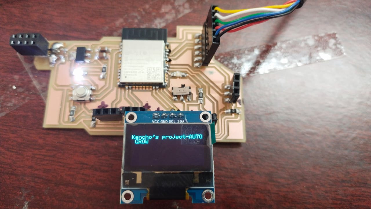
oled.println("Kencho's project-AUTO GROW"); // text to display
oled.display(); // show on OLED
}
void loop() {
}
Result
12V DC pump as an output
Hardware required
- ESP32 Board.
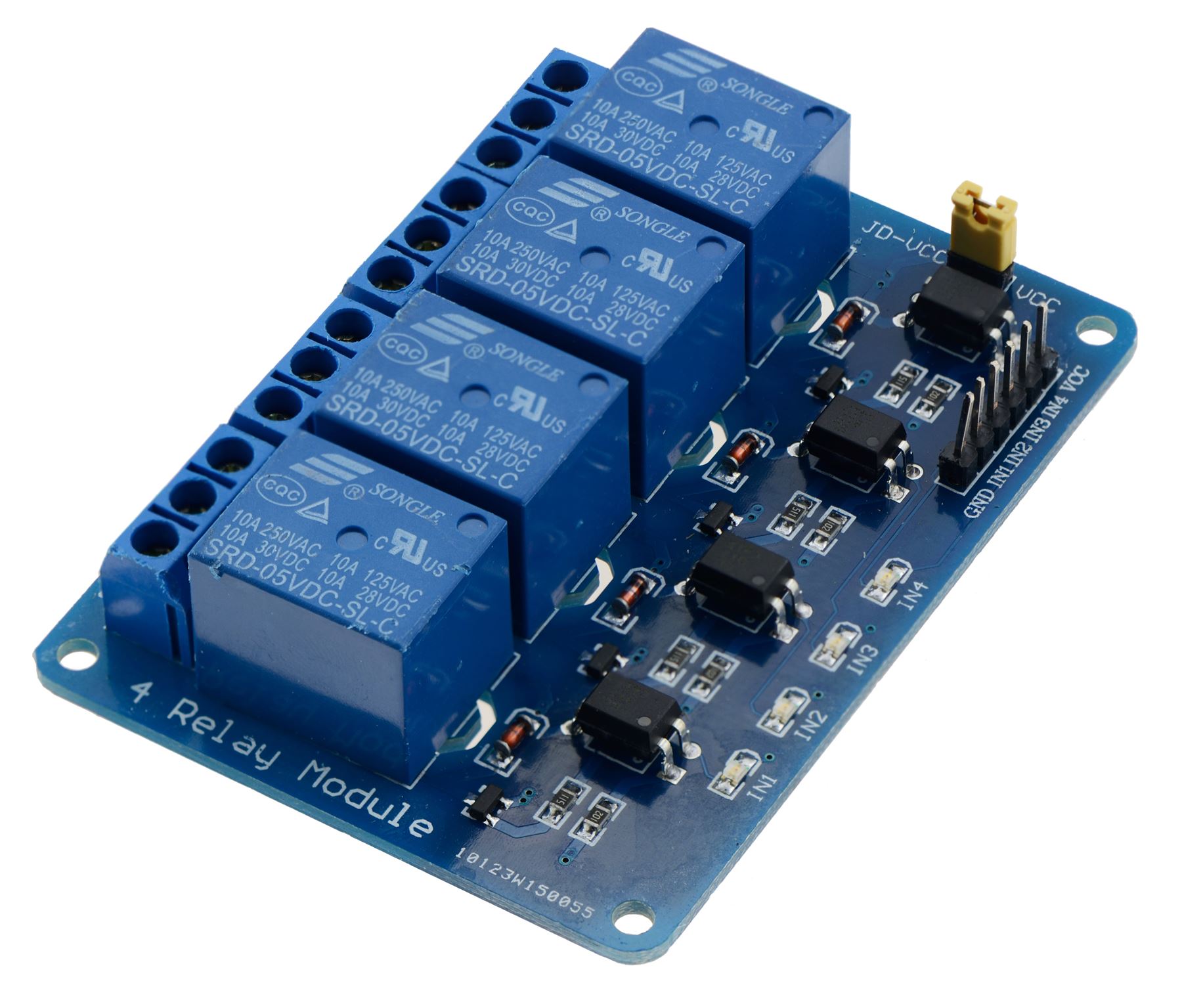
- Relay
- 12V DC pump
- FTDI Cable
- jumper wires and USB
DC pump
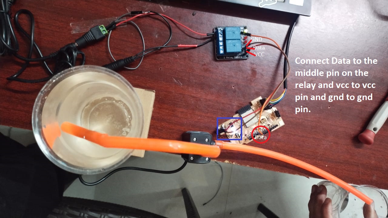
To connect DC pump to the microcontroller board we have to use a relay. Relay links low-powered digital electronics and high-powered devices. They allow digital circuits and digital microcontrollers to switch high powere devices on and off.
Circuit connection
Code
// constants won't change
const int RELAY_PIN = 13; // the Arduino pin, which connects to the IN pin of relay

// the setup function runs once when you press reset or power the board
void setup() {
  // initialize digital pin A5 as an output.
  pinMode(RELAY_PIN, OUTPUT);
}

// the loop function runs over and over again forever
void loop() {
  digitalWrite(RELAY_PIN, HIGH); // turn on pump 5 seconds
  delay(5000);
  digitalWrite(RELAY_PIN, LOW);  // turn off pump 5 seconds
  delay(5000);
}
Result
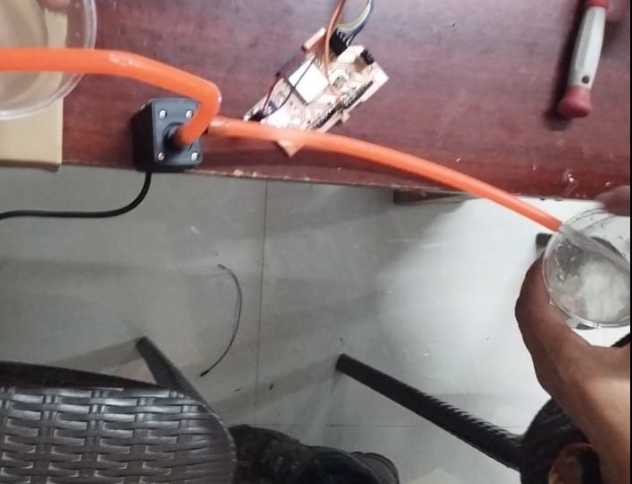
Video
Learning outcome
- Introduced to different output devices
- learnt how to use rely with different output
- Explored more on arduino programming
- Explored more on PCB designing using kicad.
ORIGINAL FILES
Download all the original files from here.