7. Electronics design
Group assignment:
GROUP PROJECT:
Use the test equipment in your lab to observe the operation of a microcontroller circuit board Details of the Group Assignment could be found here.
Individual assignment:
Redraw one of the echo hello-world boards or something equivalent, add (at least) a button and LED (with current-limiting resistor) or equivalent input and output, check the design rules, make it, test it.
SOFTWARE USED: EAGLE
Designing the PCB
Follow this steps to Design PCB with Eagle Software by Autodesk:
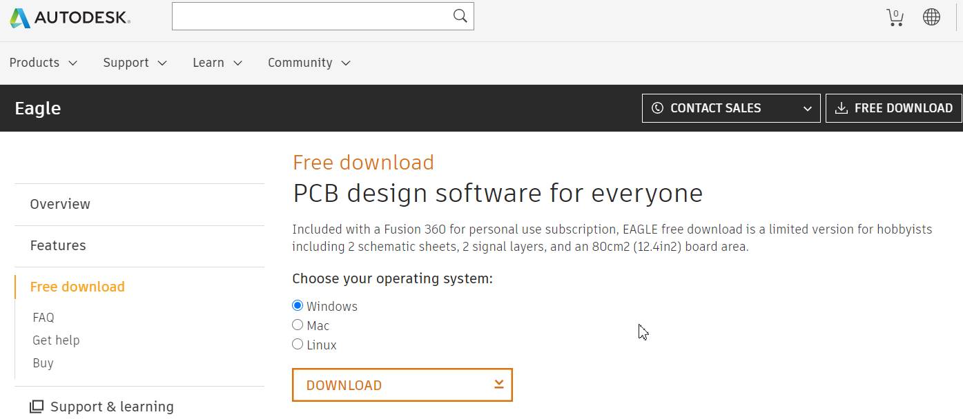
1. Download the latest version of Eagle 9.6.2 software from the website.
- To add eagle libraries, go to fabacademy website, click on Electronic Design, scroll down and click on libraries.
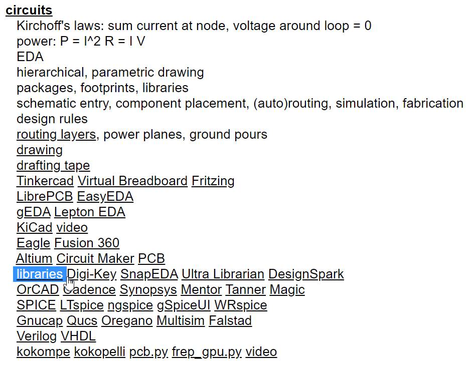
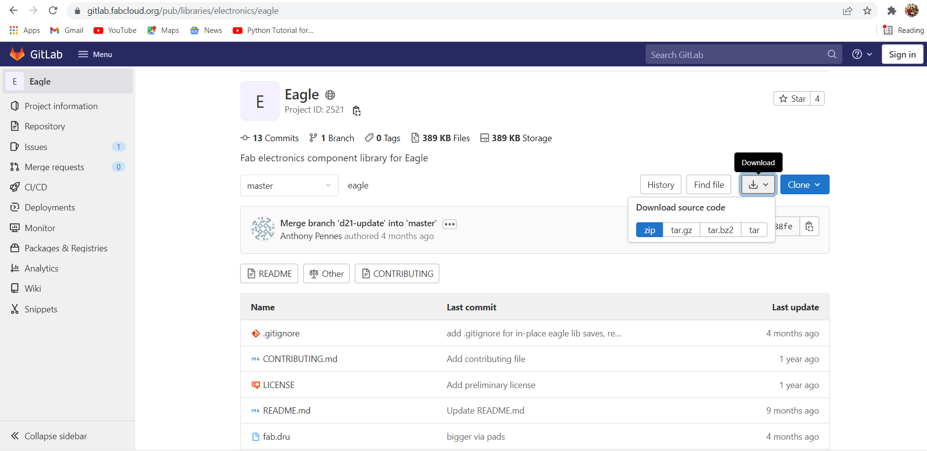
When you click on the libraries you will be directed to the page of GitHub. From there click on the eagle electronics components library and either download the zip folder or clone the http to add fab.lbr in Eagle library.
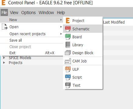
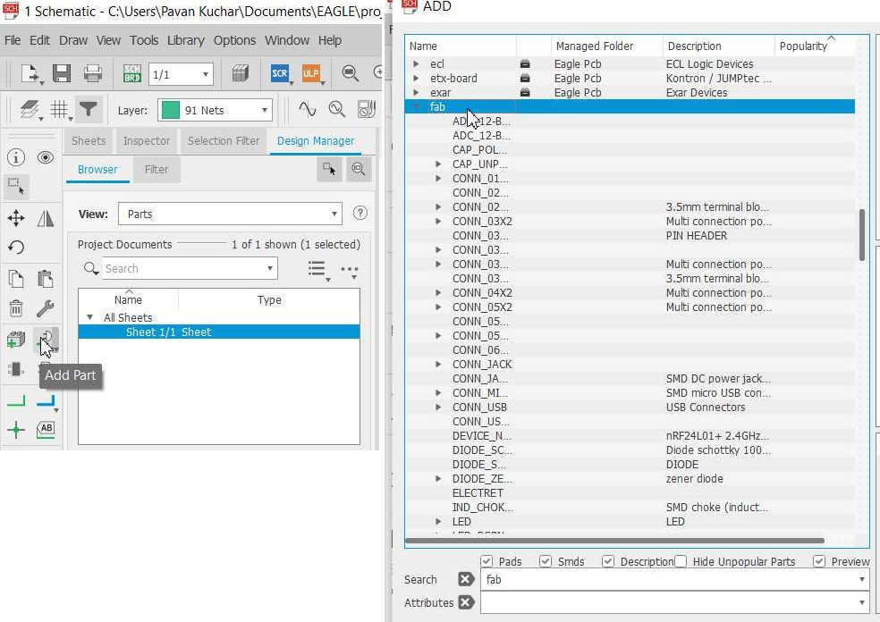
Open the Eagle software, click on file and make a new Schematic under project.
Select Add Part button on the left to add components to your new Schematic.
You can get all the components from the libraries that you have downloaded earlier from git.
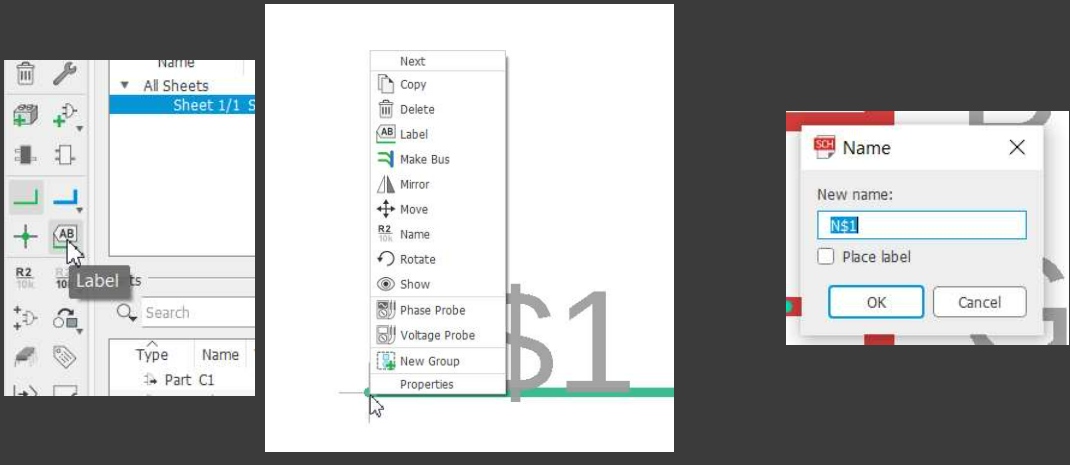
Label your components by applying net and assigning names and values.
Components used for this assignments are:
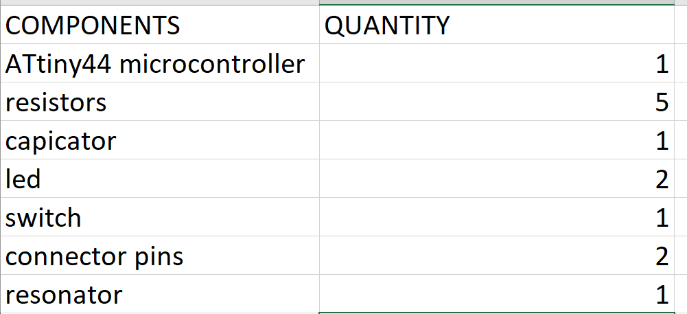
Add all the components to redraw hello world board, connect and label the components in schematic as shown in the image.
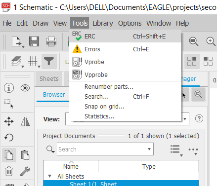
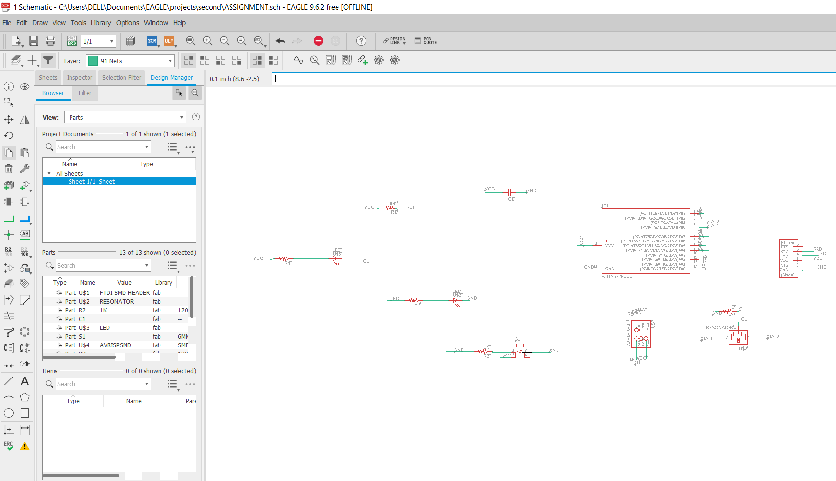 Once all the connections are made, check the errors before switching to board.
To check the errors, run ERC(Electrical Rules Check). It will show all the details of errors and warnings if there are wrong connections.
Once all the connections are made, check the errors before switching to board.
To check the errors, run ERC(Electrical Rules Check). It will show all the details of errors and warnings if there are wrong connections.
Fix all the warnings and now switch from schematic to Board.
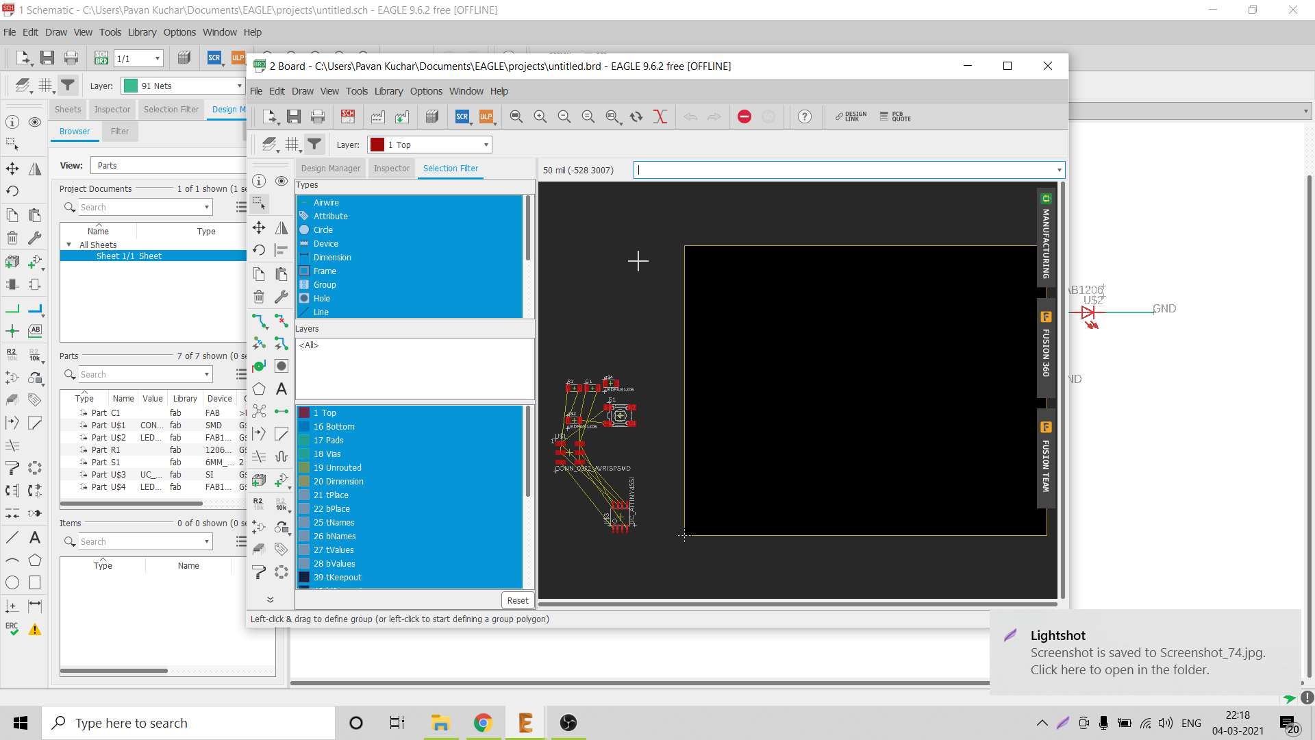
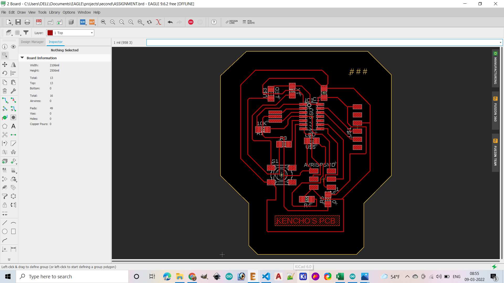
Once the board is created, drag the components inside the board, arrange and route the components in such a way that there is minimal crossing of connections.
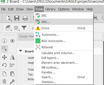
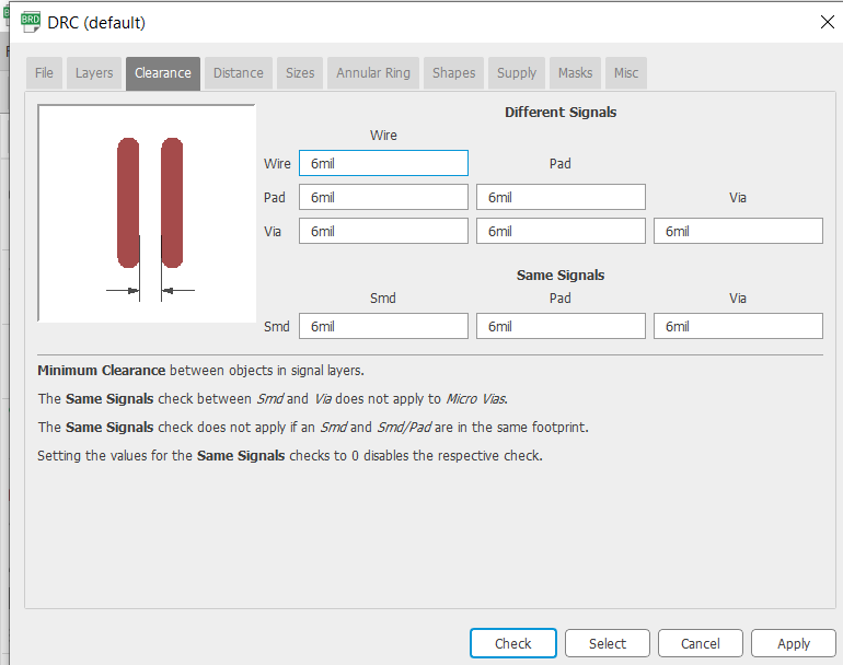
Check DRC- design rule check in board. Checking the DRC helps us to ensure our design don’t have any clearance, overlap and dimensional issues.
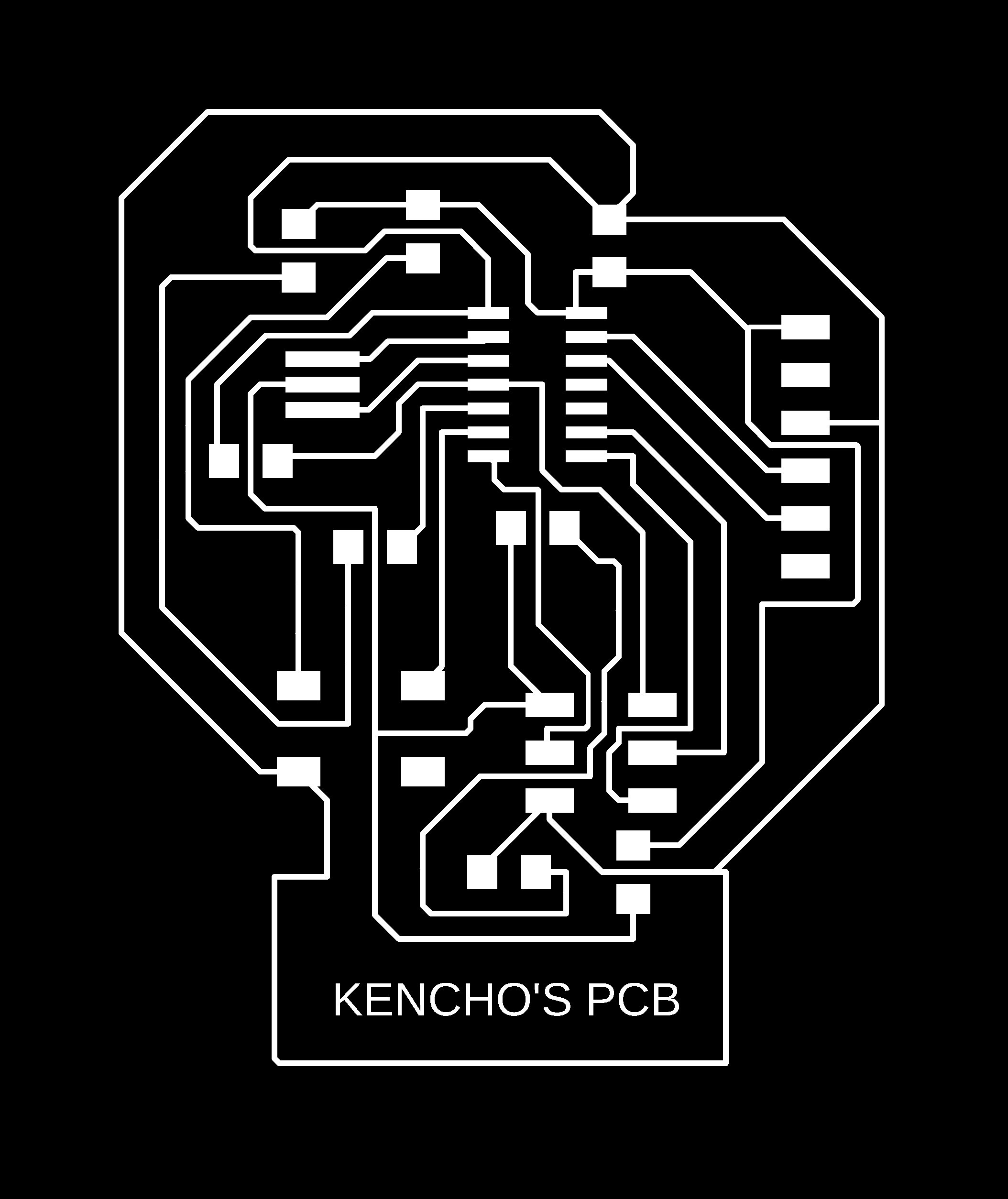
 Now export the PCB layout .
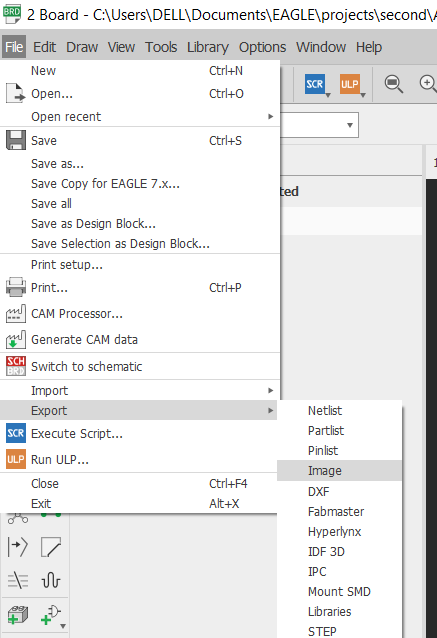
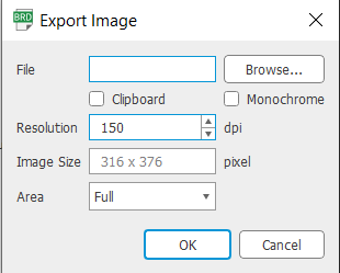
To export the file, go-to file menu and click on export and select image . Set resolution, image size and area of the image.
Now export the PCB layout .
To export the file, go-to file menu and click on export and select image . Set resolution, image size and area of the image.
PCB MILLING BY SRM-20.
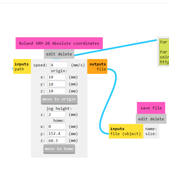
For milling my PCB board I have used Roland SRM 20 machine. Steps followed to mill the PCB; 1. Run modsproject on the computer that is connected to SRM-20.
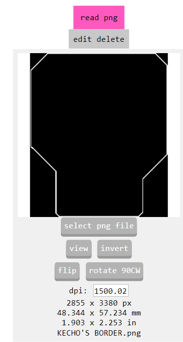
- Select the PNG image of your PCB design. And check it’s dpi (resolution)
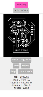
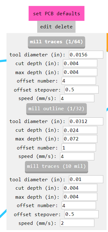
- Select the mill traces 1/64 for milling the traces of your PCB.
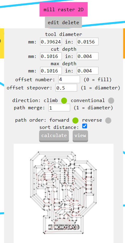
- Calculate the path.
- Create a new websocket by deleting the previous socket and connect the input file with the output file.
- Once the traces is milled, mill the outline of the PCB by selecting the 1/32 milling bit.
HERE ARE MY TRACES AND OUTLINE OF PCB BOARD

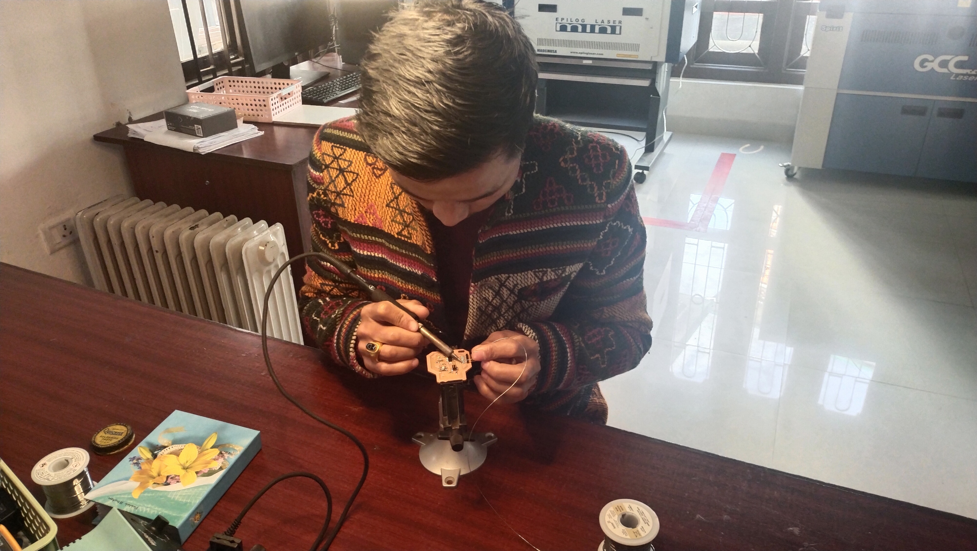
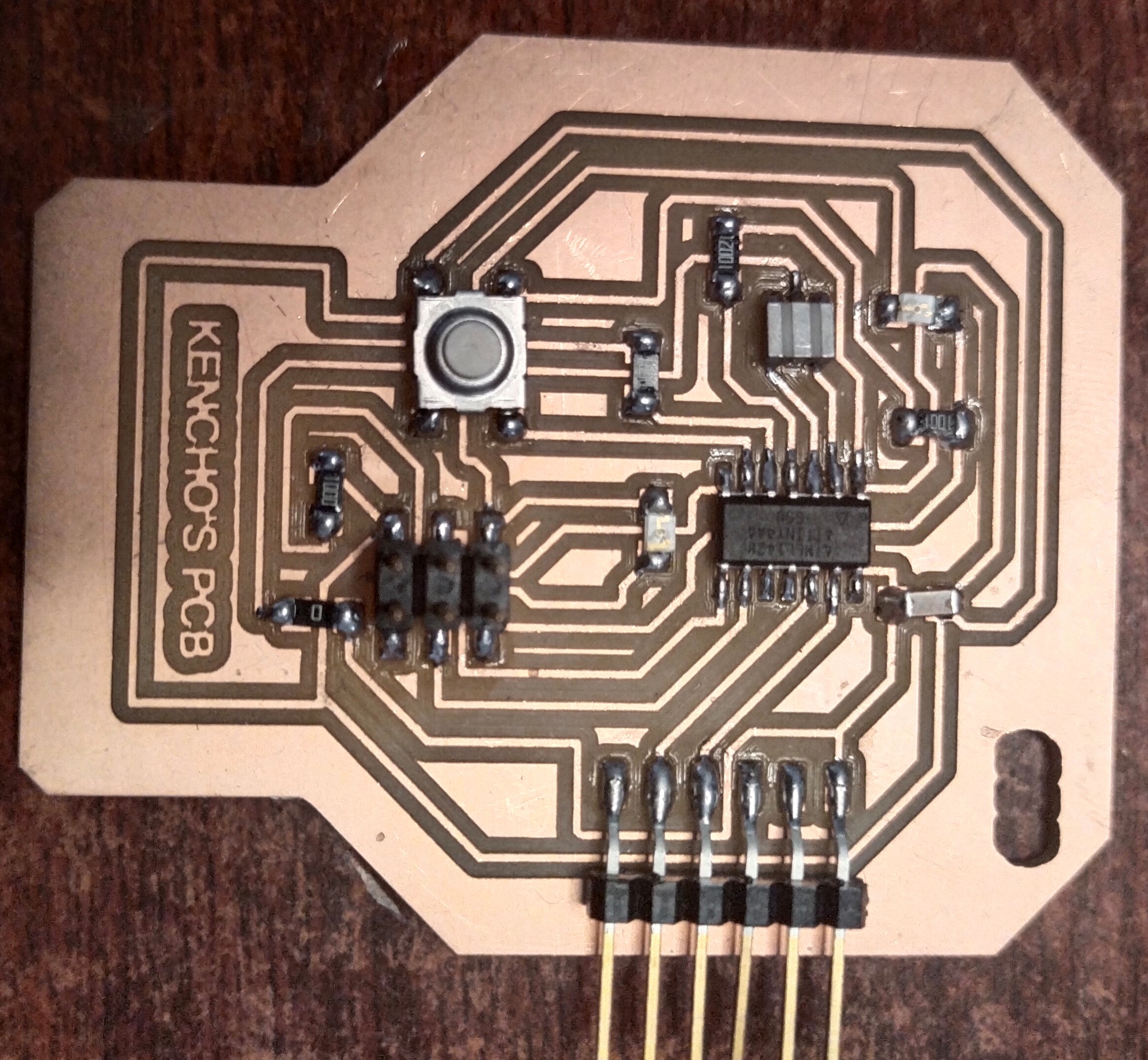
Soldering of the components.
Once the PCB is milled, solder the components by checking the connectivity with multimeter to ensure proper soldering and connectivity.
 soldered PCB
How to calculate value of current limiting resistor.
To calculate the value of current limiting resistor I used ohm’s law.
Ohm’s law V=IR
For SMD LED 1206, The Vf range is from 2.8 to 3.8V and the If max is 25mA.
we know the voltage coming from source is 5V.
Therefore,
R=5-2.8/20*10^-3 R= 110ohm.
Programming the PCB
For programming the hello world board I have used Arduino 1.8.18. To prepare your programming first Install Arduino IDE on your desktop.
Arduino doesn’t support ATtiny 44, so we have to update it’s library and add the required programmer, board, and processor.
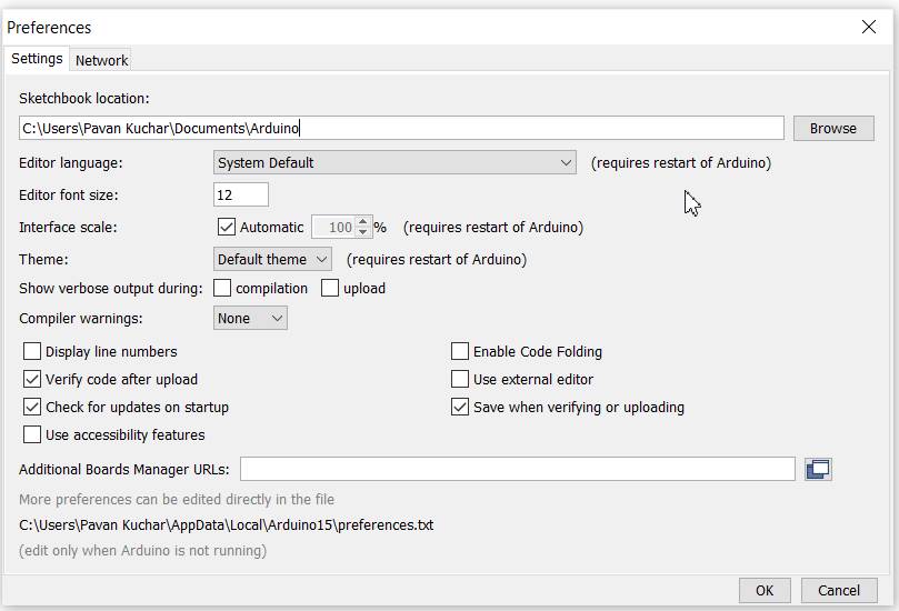
To update the Arduino library, Go to preferences under file menu.
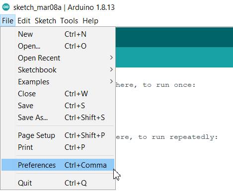
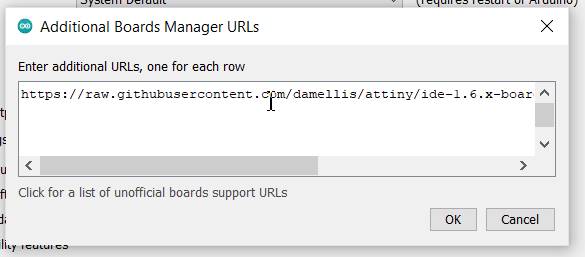
Add the additional board url in the box.
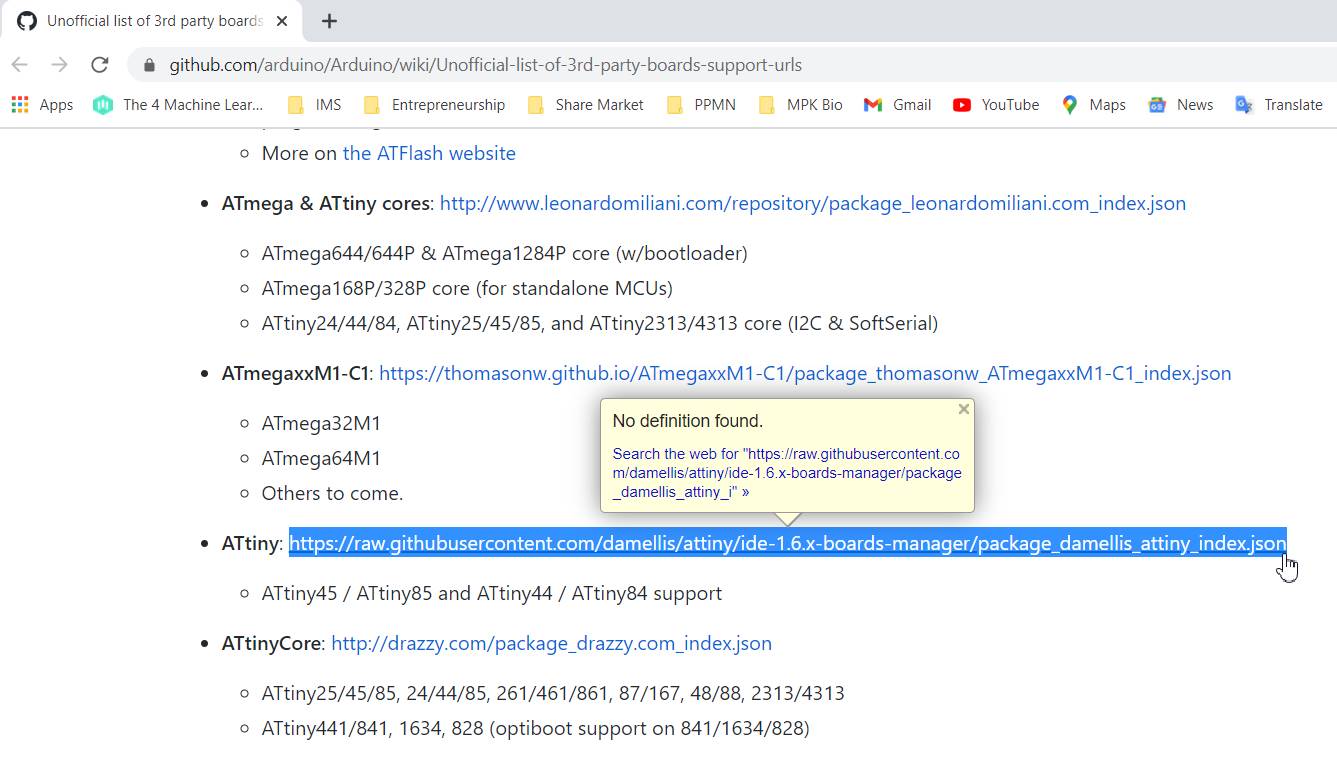
To add the ATtiny libraries click on this link and paste the link in the box.
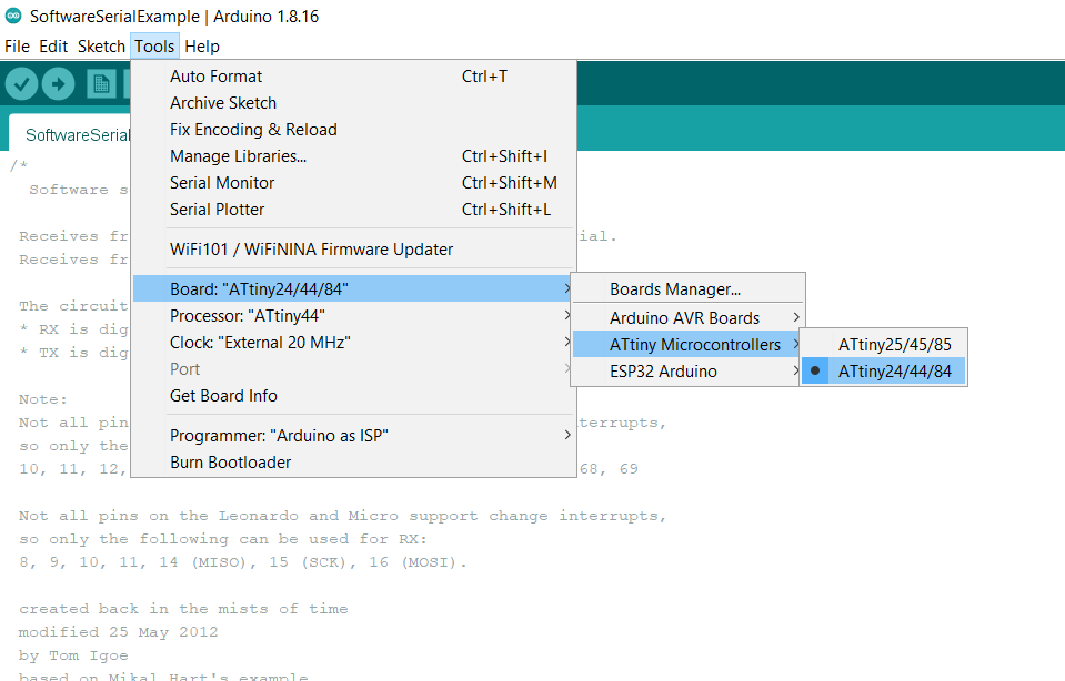
 Now the additional board will be installed and can be found in the TOOLS menu under Boards, Processor, and Programmer.
To programme your board you can either use arduino uno or fab isp.
Follow the following steps to programme your board using Arduino or fabisp.
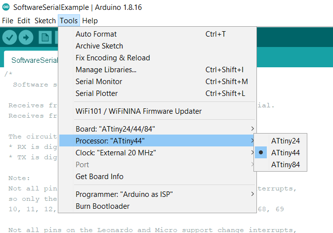
1. Go to Tools and select ATtiny 24/44/84 group from boards manager as shown in the image above.
2. Then select ATtiny 44 as processor as shown in the image below.
-
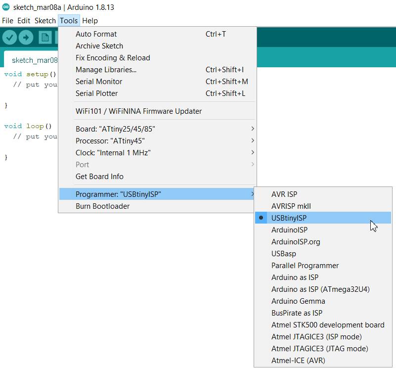
Now choose the programmer that you wanted to use to programe your board. If you wanted to use fabisp, choose USBtinyISP.
-
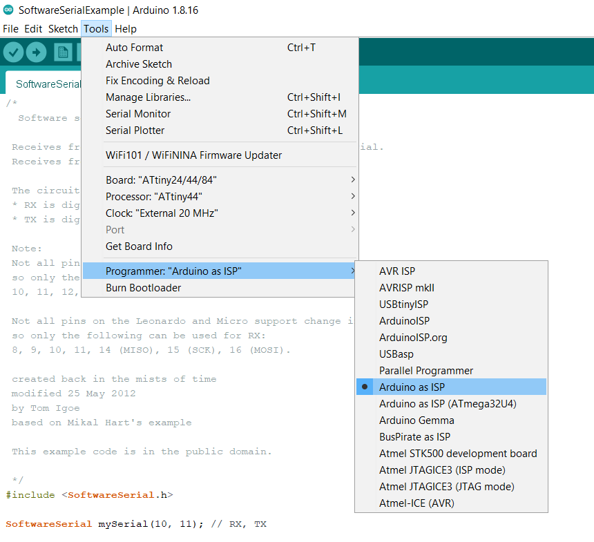
Or if you are using arduino, select Arduino as ISP.
-
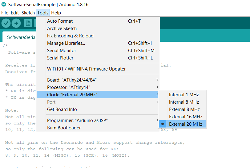
Select External 20 MHz as clock. May be it will be different in your case.
Now connect the Fabisp or arduino with ATtiny 44 PCB hello world board through AVR ISP connector pin (ribbon cable).
Make sure that the GND and VCC pins of Fabisp or arduino are connected to the GND and VCC pins of ATtiny44.
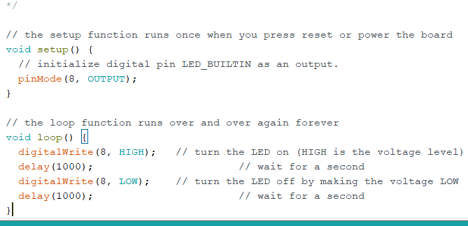
Basic programmed examples are already given in the Example File menu.
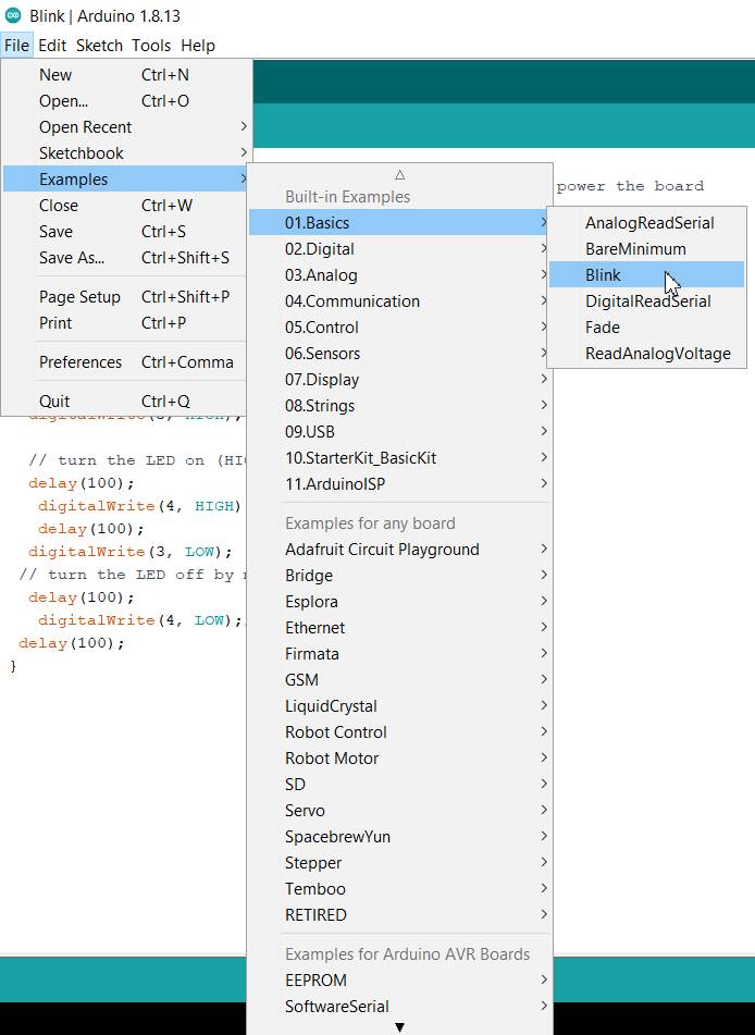 You just need to edit the program as per your led pinout. For me, my LED is connected to pin no. 8.
Video Stream of the LED’s Flashing after programming the ATtiny44:
Learning outcomes
- Learnt how to design PCB board using Eagle software
- Learnt how to add eagle libraries
- Learnt different eagle tools.
- Learnt how to fix warnings
- Learnt how to route
- Learnt how to calculate value of resistors.
- Gained more experience using SRM-20 and MIT MODS
- Learnt how to programme my board using Arduino Ide
Original files.
Download the original files from here. week7 files
THANK YOU.