8. Computer controlled machining
Assignments
Group assignment
Do your lab’s safety training Test runout, alignment, fixturing, speeds, feeds, materials, and toolpaths for your machine
The Link to the Safety Training is available HERE while the link to the design and runout test is available HERE
Individual Assignment; make (design+mill+assemble) something big (~meter-scale)
Before I document about what I have designed and milled for the week, let me jot down few safty measures that our instructor have taught us in FabZero program.
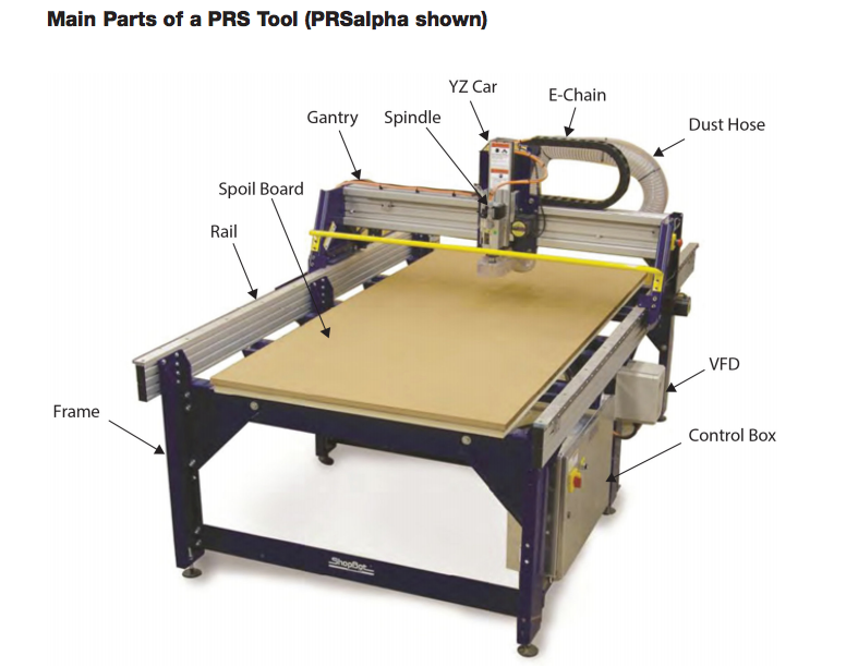
SHOPBOT ALPHA
During my fab zero we learnt to use shopbot PRS-ALPHA95/48.
Instructor: Sibu Saman
Sibu instructed us about the safety measures that we have to keep in mind while operating the shopbot. Below are the safety measures that we have to keep in mind. 1. Always cover or wear proper shoes to avoid your feet getting hurt from falling object. 2. Always roll up your sleeve to avoid yourself getting struck in the moving machine. 3. Be aware of flying object from working space. For that wear safety goggles. 4. Sometime you might need to use screws to fix the material to the board properly. For that always find the safe space to screw, otherwise the bit might cut through the screws. 5. Use ear bugs if machine produces loud sound. 6. Always wear mask because the sacrificial layer produces fine dust which may be harzadous to your health. 7. For screwing the material to board avoid the x axis as it might ruin our cloths with greese. It is always recommended to climb on bed for screwing. 8. If you set the machine manually never pull hard, pull it slowly as it might damage the limits. 9. Remove the milling bit as soon as you finish working as the bit might fall automatically and break itself. 10. There are 2 sensor for x axis and each for y and z axis. 11. There are one bolt on each side of axis as Limits. 12. To set the height of z axis always use zero plate and alligator clip.
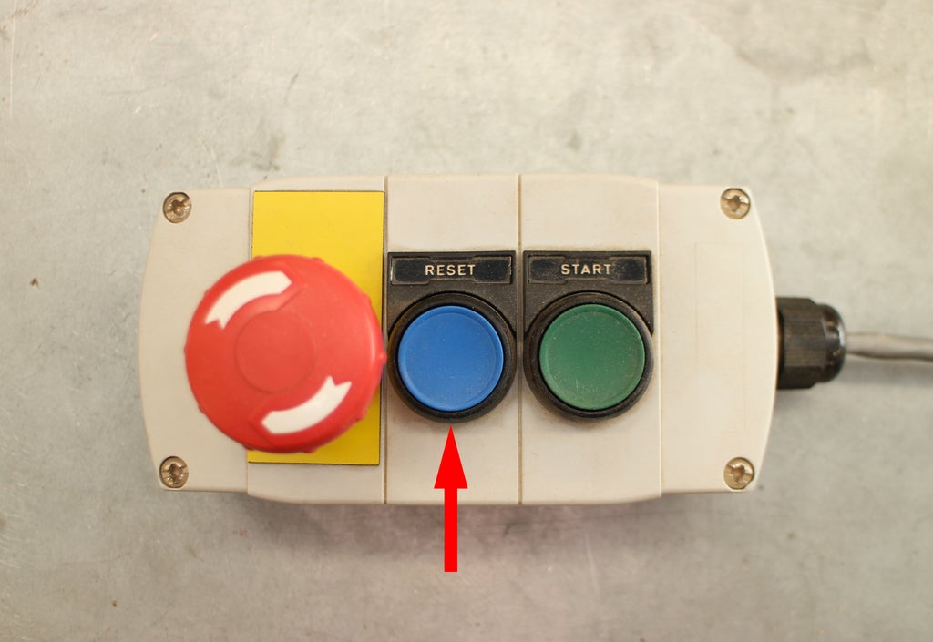
Power. 1. There are two power source to operate the machine, one for control and motion and another for spindles. 2. To switch on the spindle , there is a key on the control box. 3. To start the machine turn on the red button on the control box. 4. There are two connection to computer from control box and VFT.(variable frequency drive. 5. Tools to set spindle, the spindle tool is always connected with key. 6. Never turn in the spindle before making the spindle ready. 7. The most important safety is the emergency box. The emergency box has long wire connected to it and always carry with you. Never hesitate to press the red button if something goes wrong.
- Never left the work unattained.
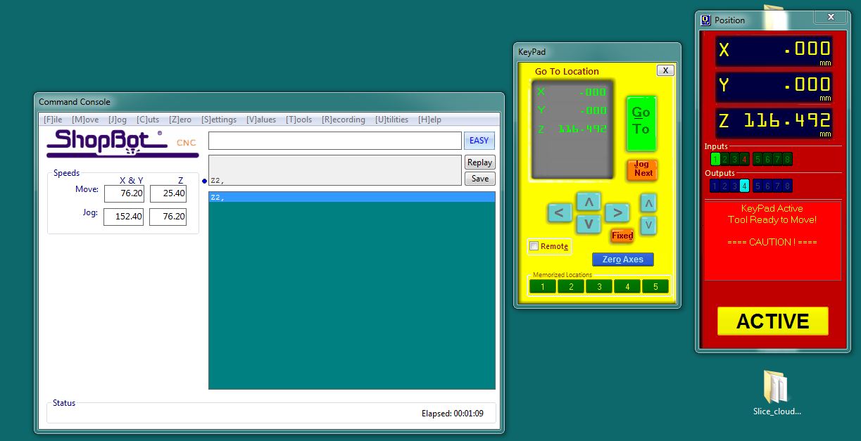
SOFTWARE
CONTROLLER SOFTWARE: SHOPBOT 3, COMMAND CONSLOE, V-CARVE FOR GCODE GENERATING.
- Always read the pop up message when you open the software.
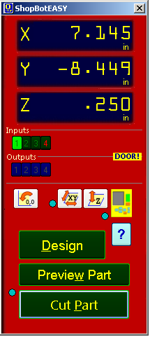
- Once open the software, first set x and y axis.
- Click on the x,y button to set xy to origin. If you click cancel, x and y axis will move to it’s machine origin. If you click yes, the x,y and z axis will move to it’s origin.
There are 2 coordinate system in shopbot ie; machine and users. Machine coordinate system is the one that you set initially using x, y and z whereas user coordinate is the origin where you set from where you wanted to start milling on your material.
- You can set the origin manually or even using the joystick option.
- The maximum x axis on the shopbot is 2500 and y axis 1250.
- Once you finished setting the x and y axis, set z axis
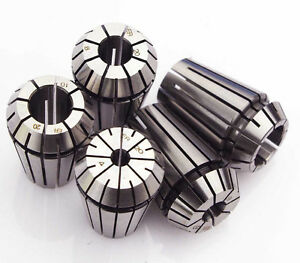
- To set the z axis make the tools ready to fit the bits and collet.
- Use the collet tool and range to unscrew or unlock the collect to insert milling bits. Move away the collet and range to unscrew.
-
Always clean the inner side of collet and outer side of milling bit as they may contain greese if new.
-
And don’t forget to clean it after use.
- Select the range of collet and bits according what we wanted to mill.
- Insert the collet first to the machine socket and manually tighten it.
- Then insert the bit and tight it using the collect tool and range.
- Once the bit is fit in collect, set z axis. There are two ways to set the z axis. 1. On material we use and 2. On the machine bed.
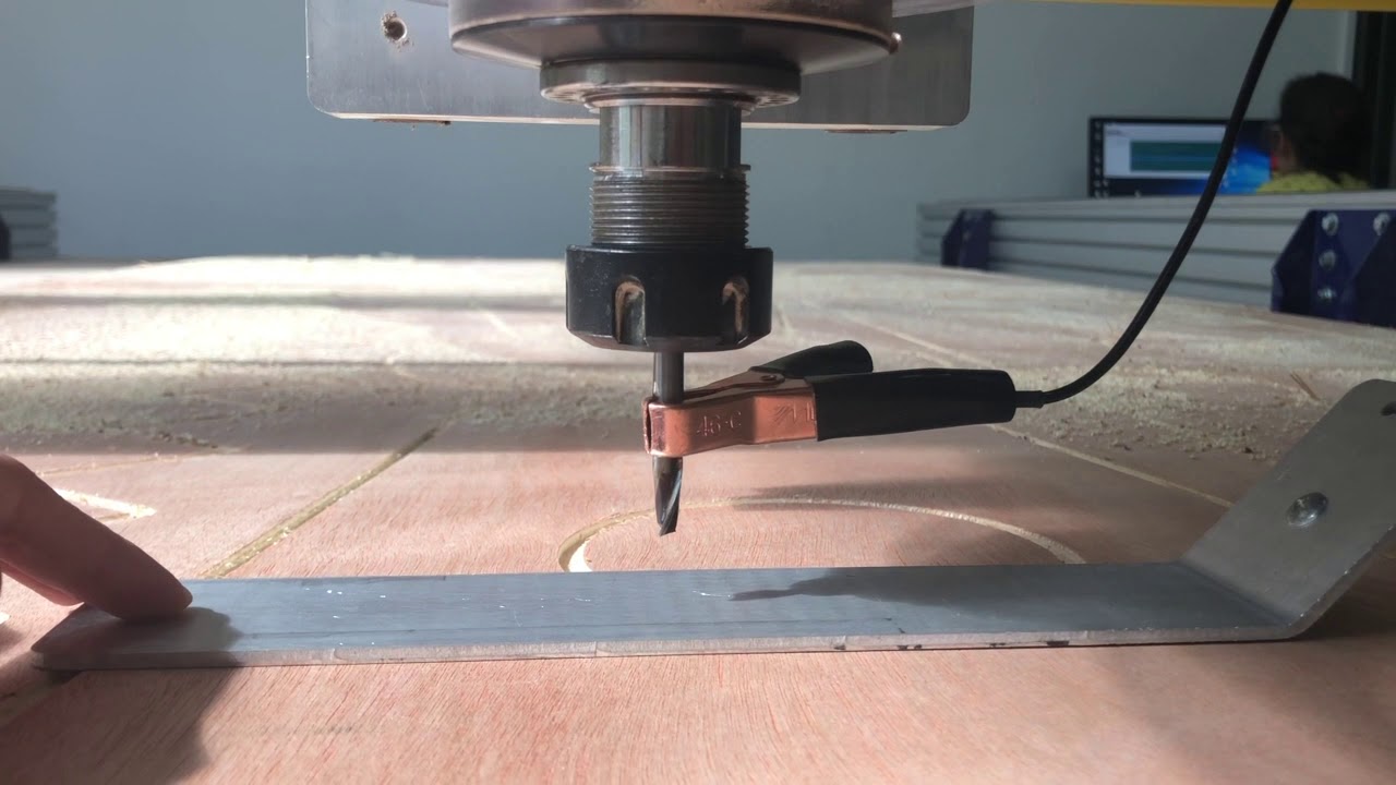
- To set z axis we need two people, one near the monitor and one near the machine. The one near the machine have to make the Al plate ready by clipping the alligator pin to spindle Al and bring the plate towards bit and touch the tip of bits. When you touch the plates to bit sensor will detect it on the monitor or software. Then bring the plate towards the bed aligning it with the tips of the bit.
- Once the plate is on the bit click enter on the monitor message box. The spindle will move and adjust it’s axis.
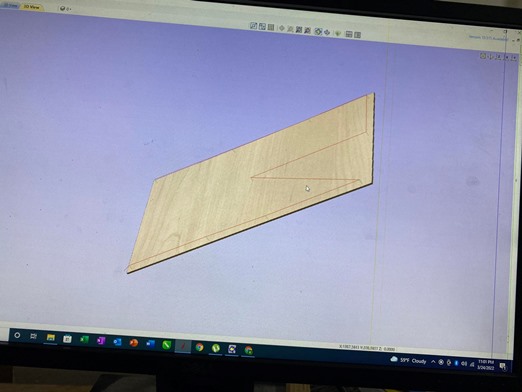
DESIGNING
SOFTWARE USED: FUSION360, BLENDER, OPENSCAD. These are the softwares that I tried for the week but I am more confortable using fusion360.
I tried to design a shoe rack and a tv stand.
Shoe Rack Design.
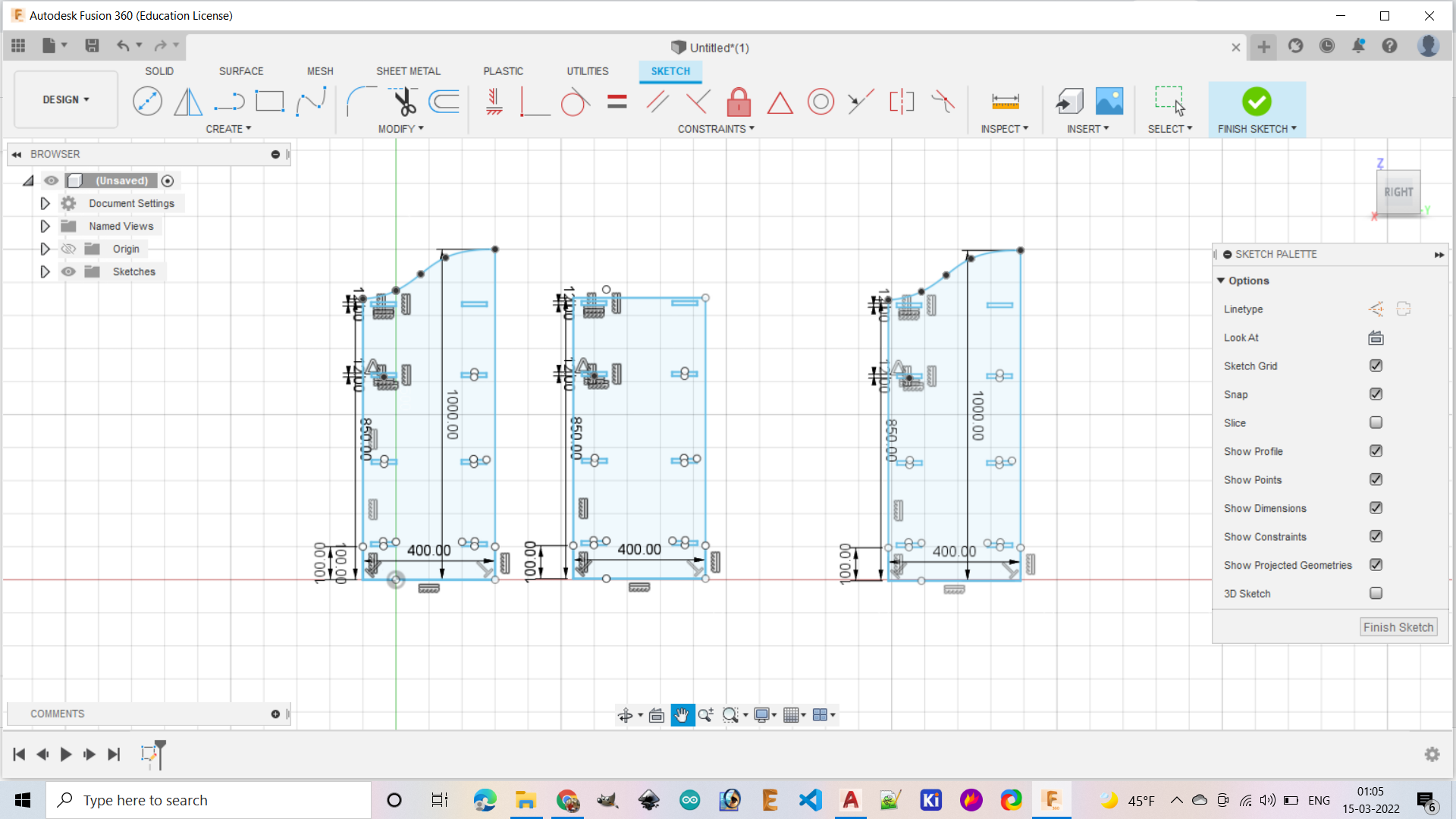
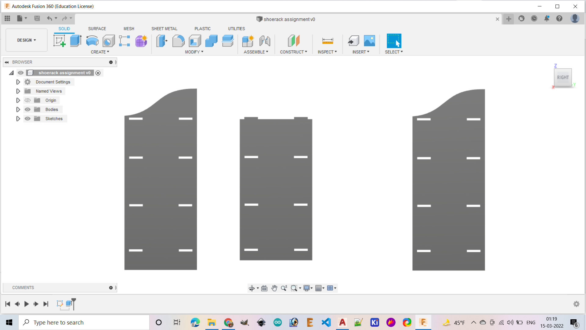
For making 2D sketch of shoe rack in fusion360 :
open the software> file> new design> create> create sketch> select a plane> select different tools and start your design> finish sketch
Once I finished my sketch I used extrude tool to set the thickness of the material. Actually we can set the parameters before the design but I forgot to set the parameters in this sketch. So I set the design thickness as per my material thickness.
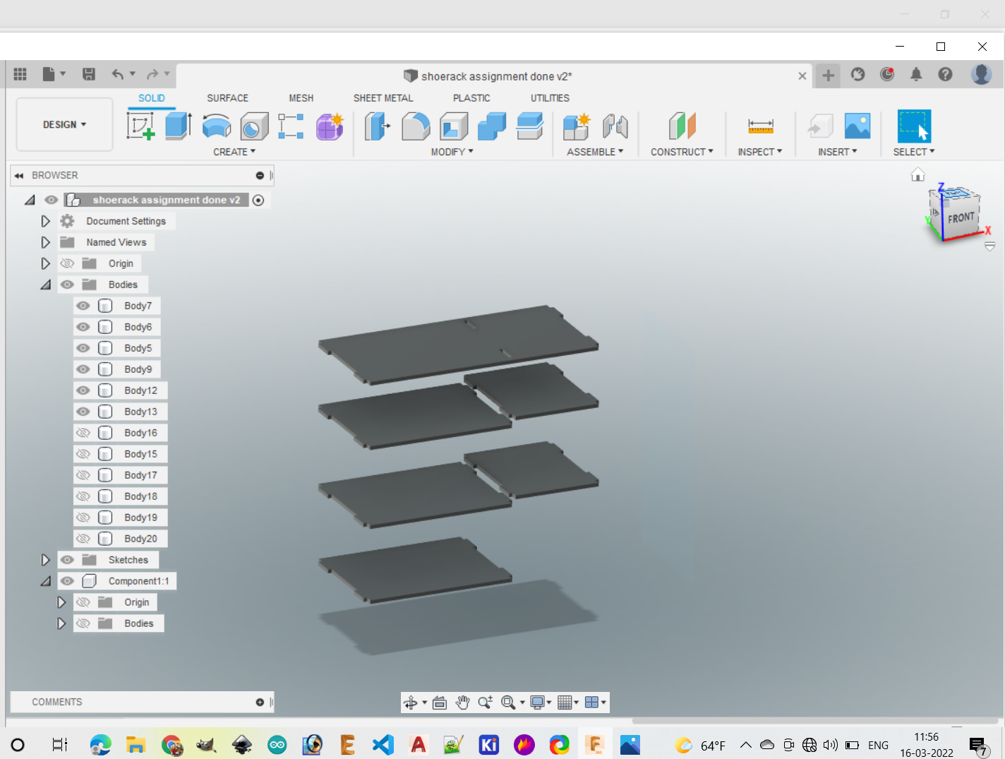
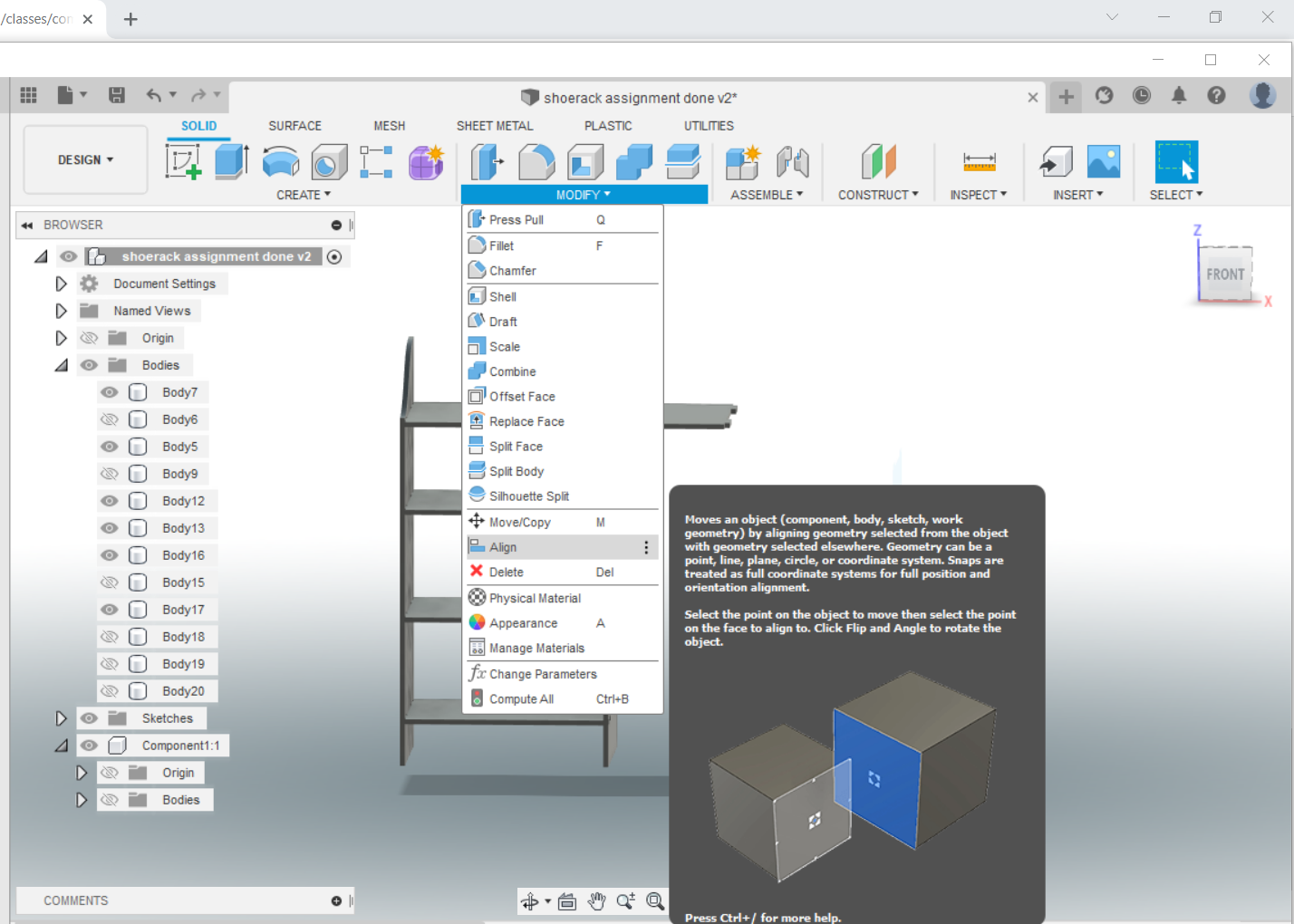
After I finished making my sketch I used ALIGN tool to aligned the parts together.
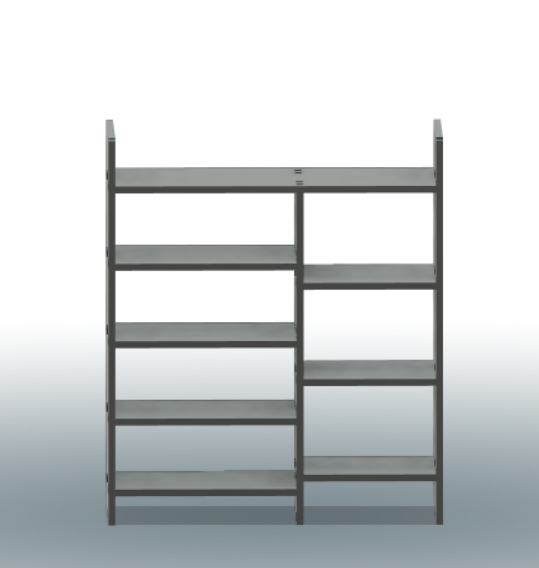
Final Sketch
TV stand
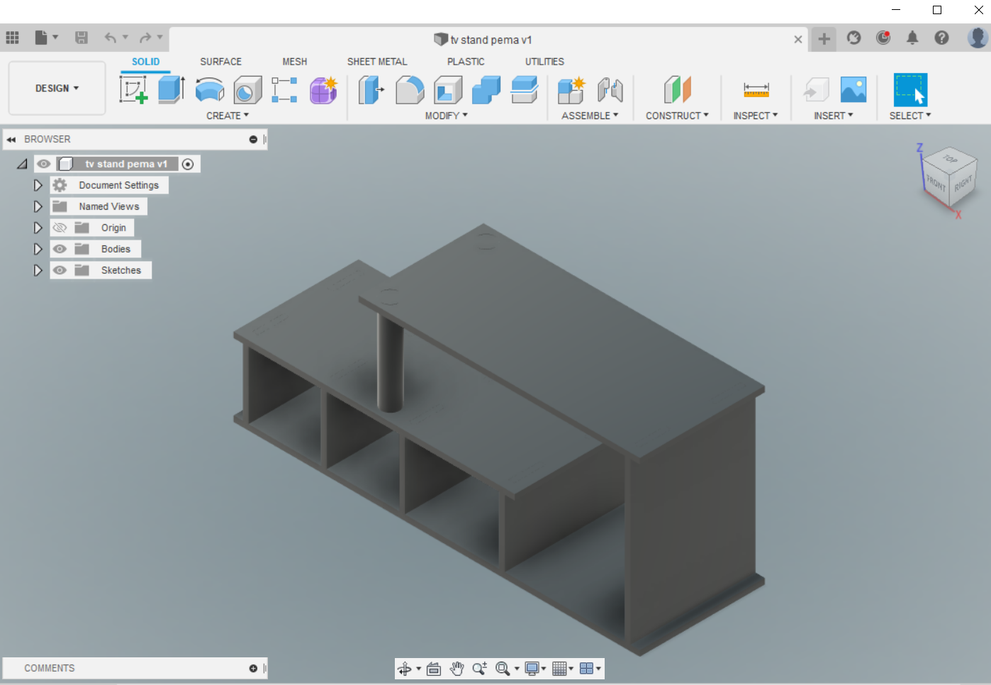
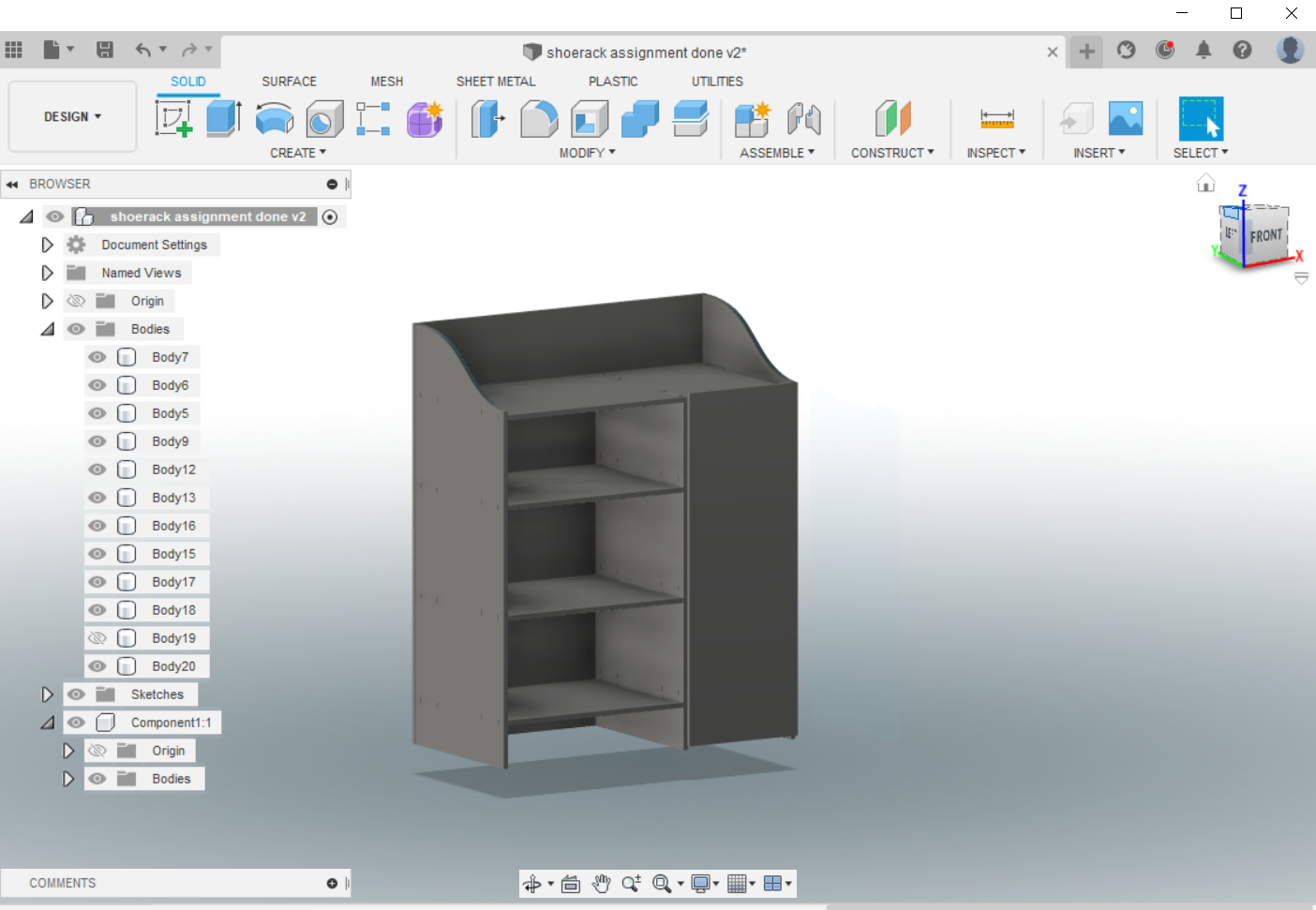
Modified Shoe rack
MILLING
During the CNC week Bhutan was under lockdown and we didn’t get wood material for milling our design.
Once the lockdown was lifted we managed to do our assignment according to the schedule provided by our lab manager. Before my schedule, I helped my friends to mill their boards which in turn helped me alot about learning the machine.
I milled the modified shoe rack in my turn. Our lab manager provided us with 18mm thick cardboard and we have to modify our design according to the material provided. Since I used parametric design it helped me to easily make the changes.
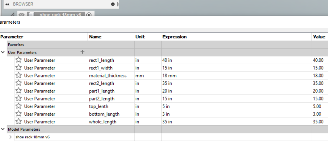
Export DXF File to Shopbot.
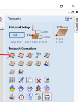
Once finished with 3D design, I exported the file in .dxf format. Then the files were downloaded to the local drive and imported in Aspire software to create tool path. Arranged the files on aspire software. Go to file >> new project.
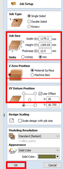
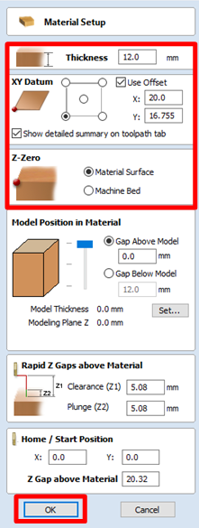
Material Setup 1. Review the job size. Make sure that your design’s width and height fit in your material (OSB board). Set thickness as same as thickness of your board. My board is 0.708 inch thick, so I set thickness as 18mm. 2. Set Z zero position as material surface 3. Set X and Y offset from left bottom corner. If you set X0 and Y0 at the left bottom end of your material in machine, your tool path will be generated offset your X Y set values. I set 16mm & 20mm offset to make sure machine does not cut edge of my board where I will place nails. 4. Press OK
- Click “Set” to review
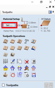
- Check thickness, offset, Z-Zero set up.
- Press OK if everything looks fine.
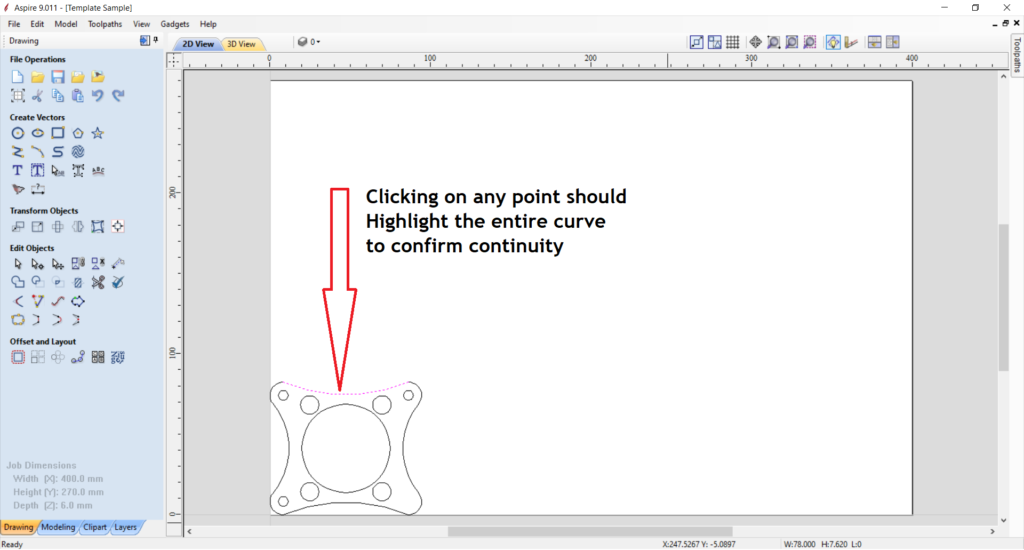
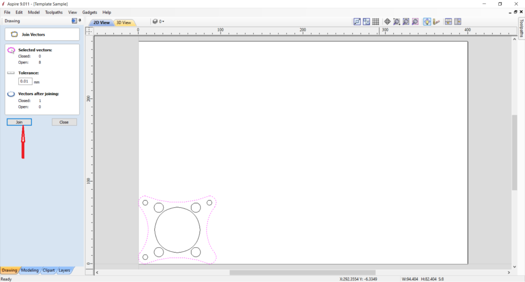
Confirming Continuity of Curves and/or Lines
- Click on any of the curves to confirm they are continuous.
- Clicking on any point should highlight the entire curve to confirm continuity. Refer the image below to understand more about the continuity of curves.
- If the curves or lines are broken use the join command.
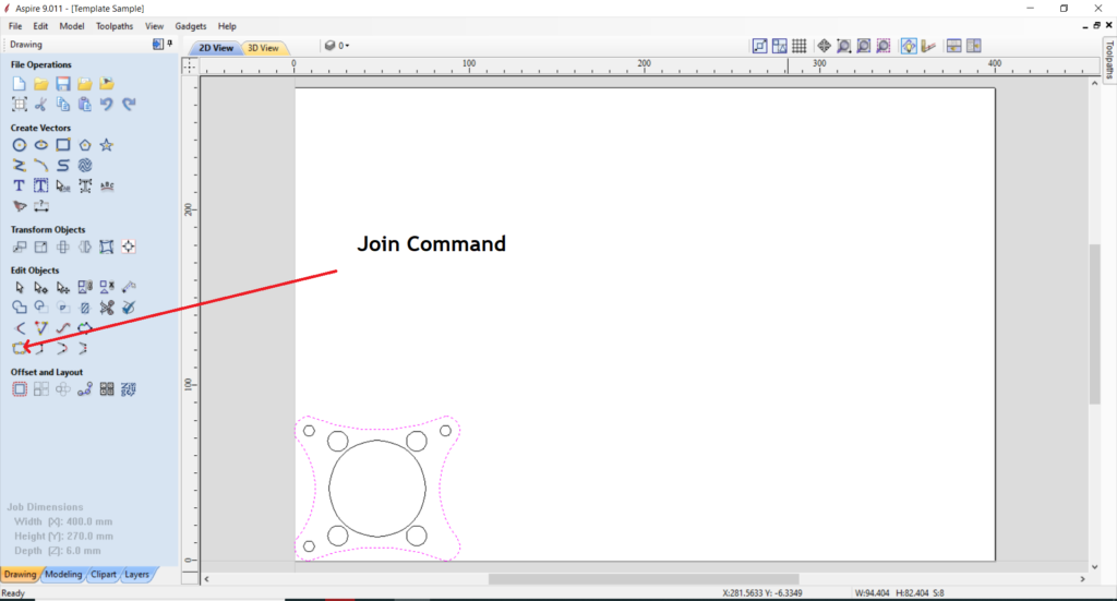
- Click on any point of the curve and hold the shift key on your computer keyboard.
- Select the rest of the curves while the Shift Key is in the down position and click Join
Drilling Toolpaths
- Once the objects are properly arranges in the Aspire window, go to toolpath > Drill Tootlpath.
- Change the starting point to 00, and end point to the thickness of our material i.e 18mm.
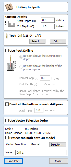
Cutdepth setting
It is safer to keep the cut depth slidely more than the material thickness tocut the material completely. In my case I increased it to 18.2mm.
Tools setting.
- Donot change the default tool setting.
- Edit the tools only for the current job.
- Following is changed based on our requirement.
- Number of Flutes: 2
- Pass Depth: 3.5mm
- Step Over: 1.2mm
- Feed Rate: 50mm/sec
- Plunge Rate: 30mm/sec
- Spindle Speed: 1800RPM.
- Once tools settings were changed, press calculate to calculate the toolpath.
- Then close and save the tool path to a specific folder.
Creating Profile Tool Paths
- Select all curves and/or lines insider the most outer curves and/or lines.
- Click Tool paths on the Top Right corner of window.
- After clicking on the Toolpaths tab, pick the first icon - profile toolpath.
- select the starting cut depth of 00 inches to the cut depth of the material thickness.
- For tool selection, Clicking the Select button opens the Tool Database from which the required tool can be selected.
- set and specify the number of passes for pass depth control for profiling.
- set the machine vectors. there are 3 option to choose from to determine how the tool is positioned relative to the selected vector/s.
- add tabs to open and close vector shapes to hold parts in plave when cutting them out of material.
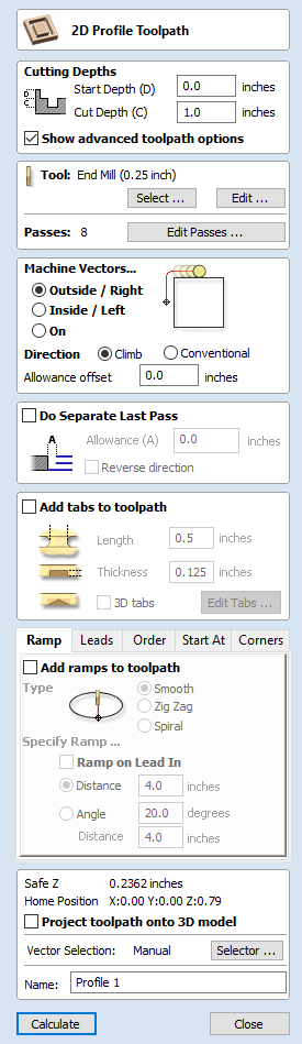
- Then save the tool path after changing the tools settings.
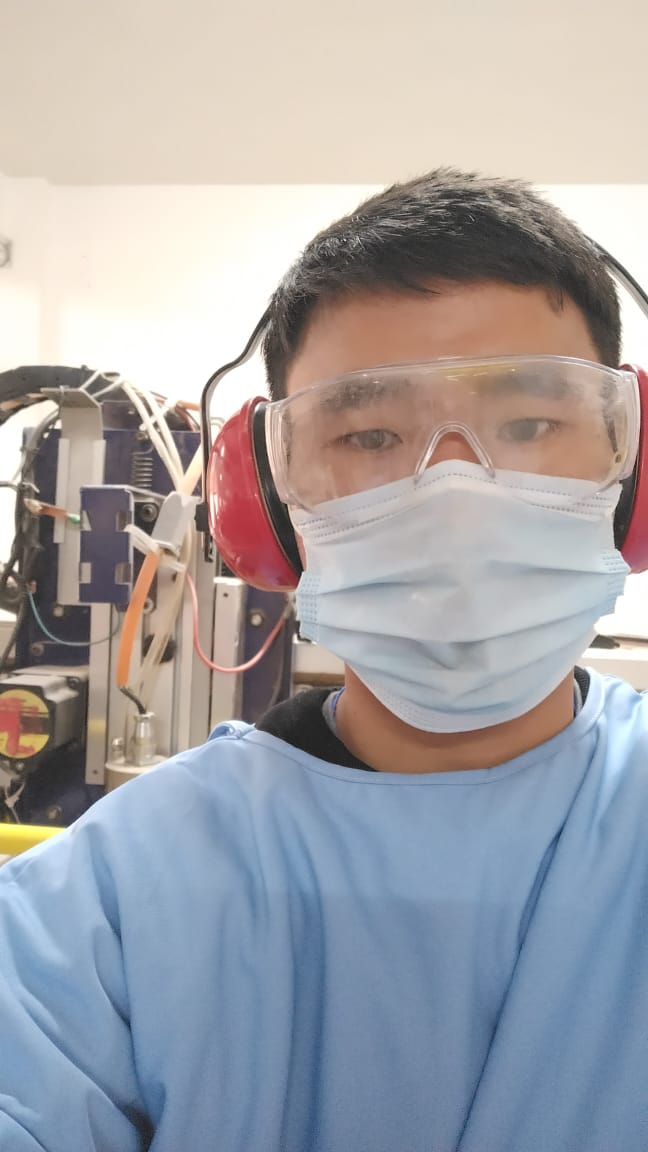
WEAR PROPER GEAR AND USE EMERGENCY STOP
Cutting in Shopbot
After the toolpaths were saved, import the toolpath file to the machine software.
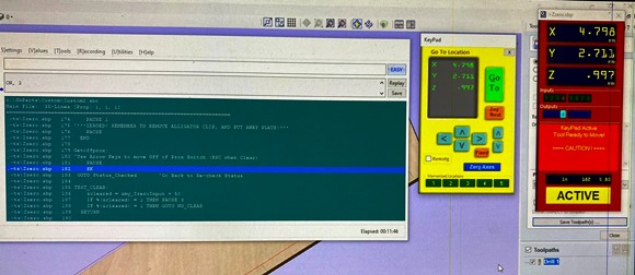
The shopbot software has two interface. One is to control the direction and other is the command console. The direction control interface can be used to control the shopbot and import the tool path.
Align the board on the bed of the shopbot and align it for drilling. Then change the desired milling bit. We use the direction control to move the shopbot in XYZ direction and bring it to the desired location to set the XYZ zeros.
Milling Bit used:
- 2-Flute Endmill
- Diameter: 8mm
- Total Length: 40mm
- Cut Part Length: 25mm
- Material: High speed steel (HSS)
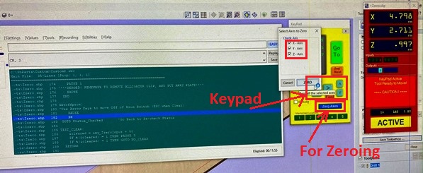
When done with zeroing load the drill toolpath on shopbot software, manually start spindle from control box (spindle speed: 4000RPM) and clcik cut.
Once drilling process is completed, use drilling machine to screw the board to hold it in place.
After the board is properly fixed, import the toolpath for the profile and send it to cut.
Final steps after cutting process is completed.
- stop the spindle using the red button on the control box.
- remove the screws.
- remove the parts and vacuum the dust.
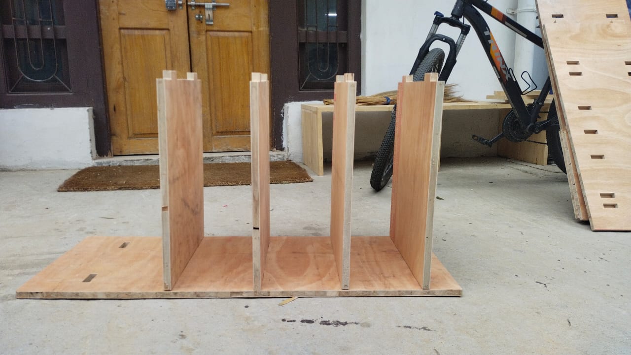
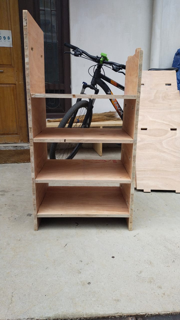
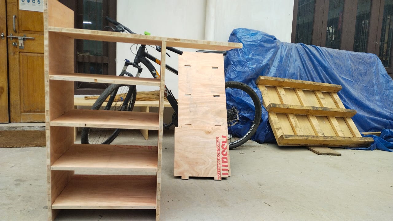
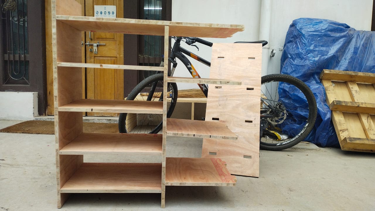
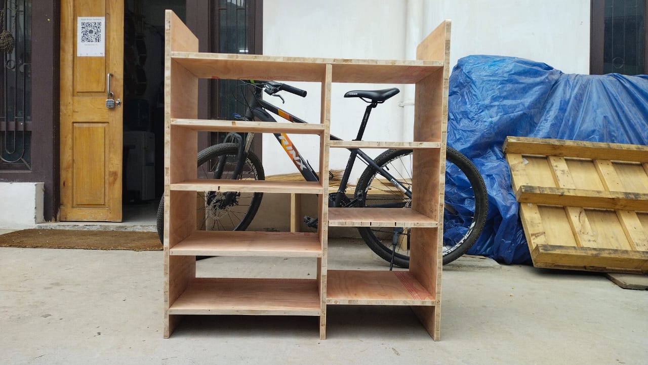
Final Cut Parts and Assembly
Assembly
Learning Outcomes
- Learnt various safety measures to keep in mind while operating the machine.
- Learnt how to make different joints in the design.
- Learnt different parts of the machine and their functions.
- Learnt different tools in fusion 360.
- Leanrt a new software, ASPIRE.
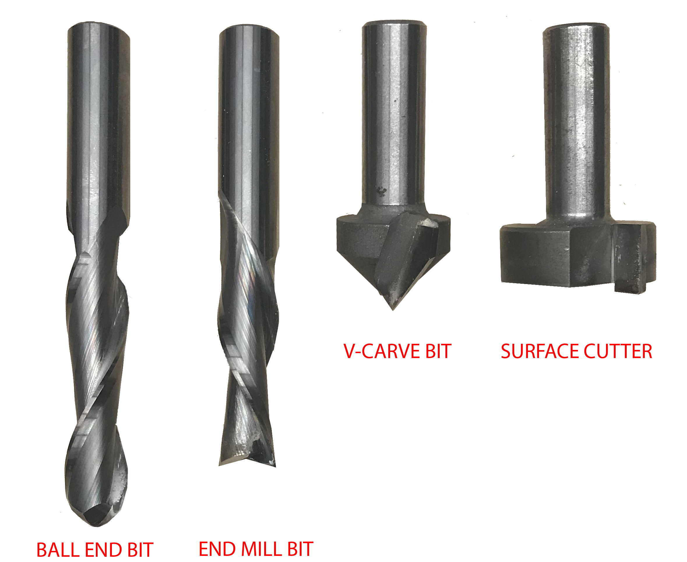
- Learnt about different milling bits and their different usage.
ORGINAL FILES
Download all the original files from here.