11. Input devices
Before I write down about what I did for the week let me quickly refresh your brain by heightlighting the some of the important key words, their types and meanings.
Input Devices
Input Devices are the devices or the sensors that receive data or a set of instructions from the outside world and translate the data into a machine readable format.
They are the interface between the outside world and the computer for better communication.
Types of sensors.
## Active Sensors
Active sensors are the type of sensors that produces output signal with help of external excitation supply. The own physical properties of the sensor varies with respect to the applied external effect. Therefore, it is also called as Self Generating Sensors.Examples: LVDT(Linear Variable Differential Transformer) and strain gauge.
Passive Sensors
Passive sensors are the type of sensors that produces output signal without the help of external excitation supply. They do not need any extra stimulus or voltage. Example: Thermocouple, which generates a voltage value corresponding to the heat, applied. It does not require any external power supply.
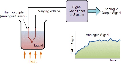
Analogue Sensors
Analogue Sensors produce a continuous output signal or voltage which is generally proportional to the quantity being measured. Physical quantities such as Temperature, Speed, Pressure, Displacement, Strain etc are all analogue quantities as they tend to be continuous in nature. For example, the temperature of a liquid can be measured using a thermometer or thermocouple which continuously responds to temperature changes as the liquid is heated up or cooled down.
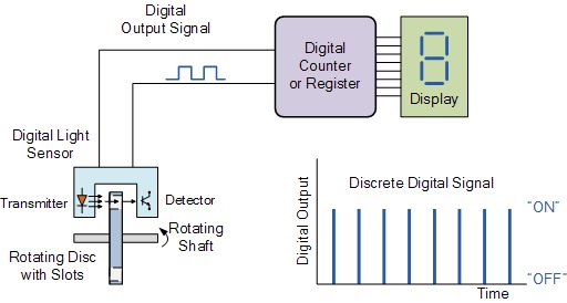
Digital Sensors
As its name implies, Digital Sensors produce a discrete digital output signals or voltages that are a digital representation of the quantity being measured. Digital sensors produce a Binary output signal in the form of a logic “1” or a logic “0”, (“ON” or “OFF”). This means then that a digital signal only produces discrete (non-continuous) values which may be outputted as a single “bit”, (serial transmission) or by combining the bits to produce a single “byte” output (parallel transmission).
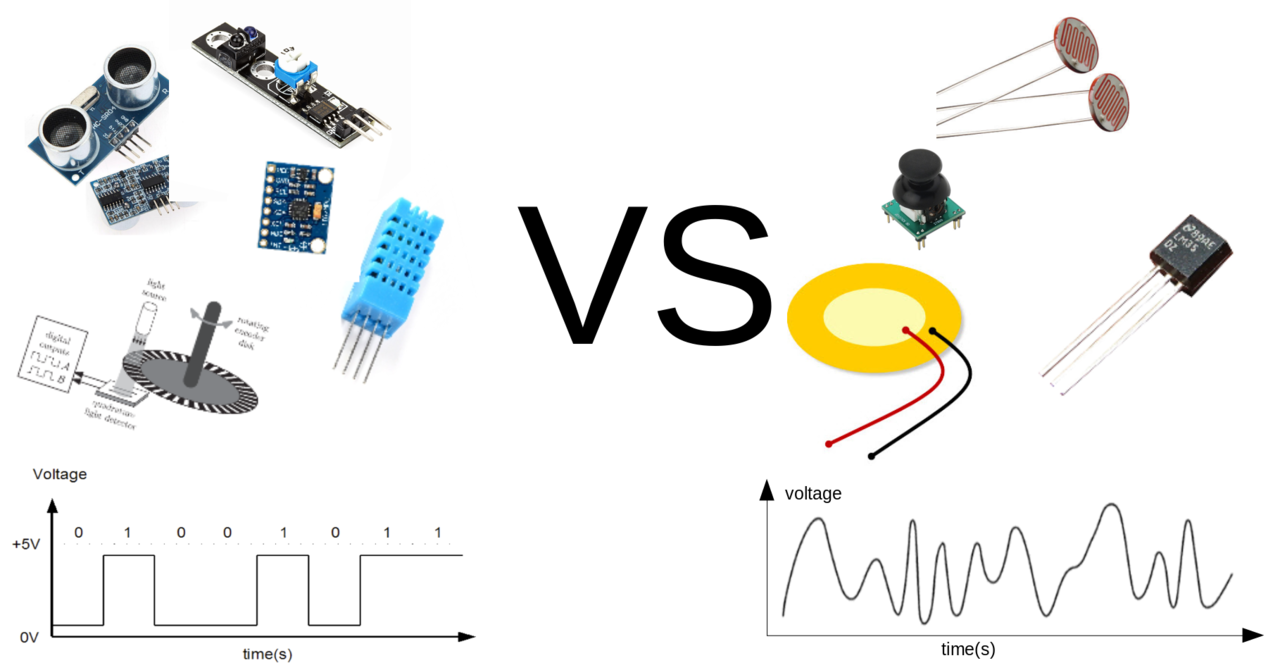
Output of digital and analog signals.
Some of the sensors examples are:
- Soil moisture sensor
- PIR sensor
- Gas sensor
- humidity sensor
- Touch sensor
- Rain sensor
- Keyboards, mouse, joystick, web camera, etc..

WEEK-12 ASSIGNMENT
Group Assignment:
Probe an input device’s analog levels and digital signals.
For the Group Assignment REFER THIS LINK.
Individual Assignment:
Measure something: add a sensor to a microcontroller board that you have designed and read it.
MY OBJECTIVE FOR INPUT WEEK ASSIGNMENT.
- Use ARDUINO uno board to read DHT data
- Use Self made ESP32 Board to read DHT data.
For the Individual Assignment I wanted to use the input that I will be using in my final project.
For my final project I will be using DHT11/22 as my input to read some data from my autogrow Greenhouse and ESP32 to read temperature and humidity value from DHT11 or DHT22 sensors and print it to serial monitor.
SETUP ESP32 ENVIRONMENT FOR ARDUINO IDE.
Since I am using ESP32 for the first time, I have to setup environment for ESP32 on Arduino IDE.
Guide to set-up ESP32.
If you haven’t install Arduino IDE yet, clickhere to download.
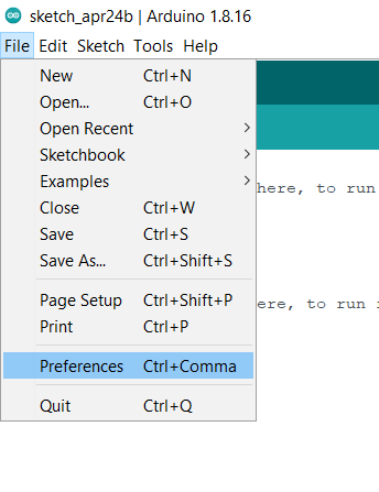
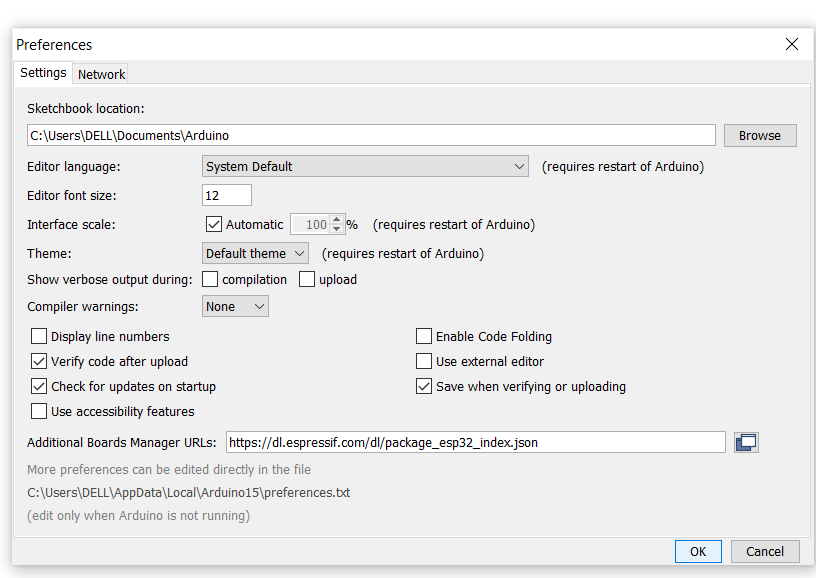
Once downloaded the Arduino IDE, go to FILE>> PREFERENCES on Arduino IDE
Copy the text below
https://dl.espressif.com/dl/package_esp32_index.json
Paste the copied link in the Additional Board Manager URLs as shown below.
Then open Board Manager by going to Tools>> Board>> Boards Manager.
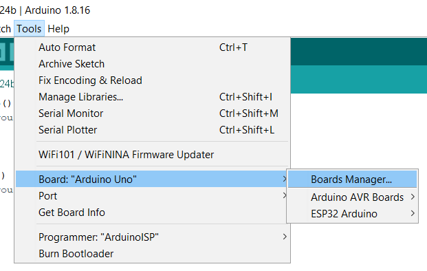
Then type ‘ESP32’ and install the ‘esp32 by espressif systems’.
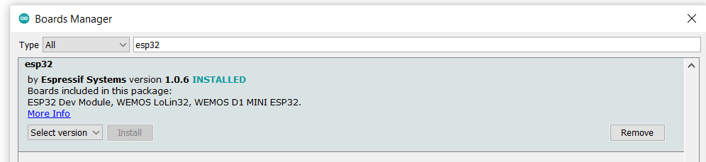
Your software is successfully installed.
Now make your tools ready in Arduino IDE by selecting the right board, port, programmer and run the codes.
## USE ARDUINO uno board to read DHT data.
Things needed for this connection 1. Arduino Uno 2. USB cables 3. DHT sensor
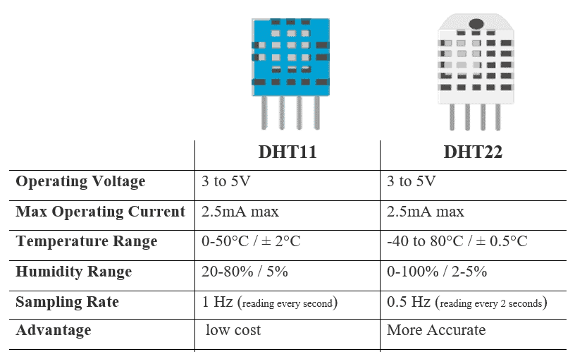
DHT11 vs DHT22
The commons between DHT11 and DHT22 1. They have the same pinout 2. They have the same wiring to ESP32 3. They have the similar Esp32 code.
The differences:
PINOUT for DHT11 and DHT22 sensors:
4 PINS
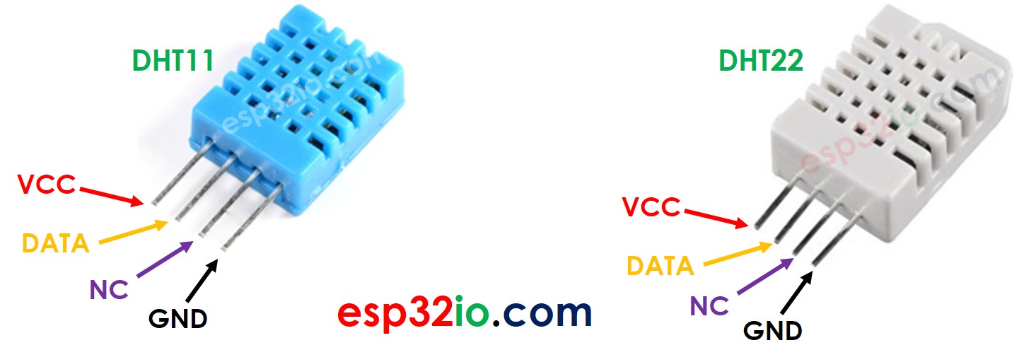
- GND pin: connected to GND(0V)
- VCC pin: connected to VCC (3.3V)
- DATA pin: Pin used to communicate between the sensor and eps32.
- NC pin: not connected.
But the DHT sensor module that have 4 pins usually don’t have a built-in resistor, so for that we have to use 10K ohm resistor.
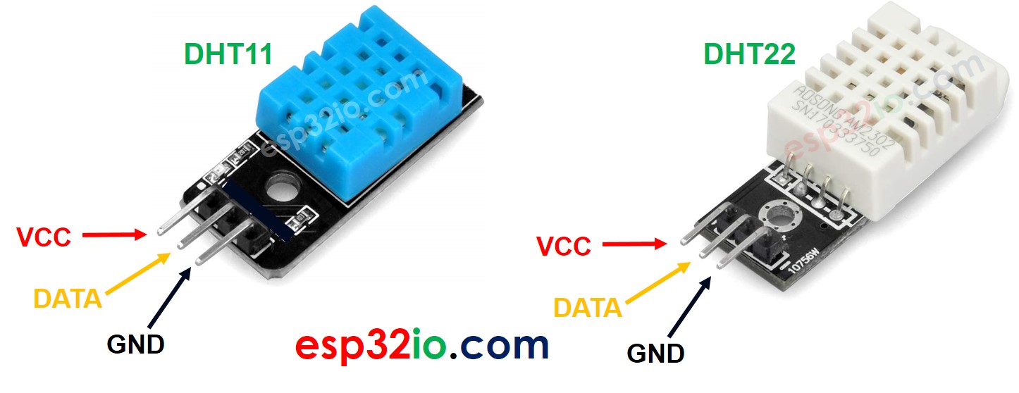
3 PINS
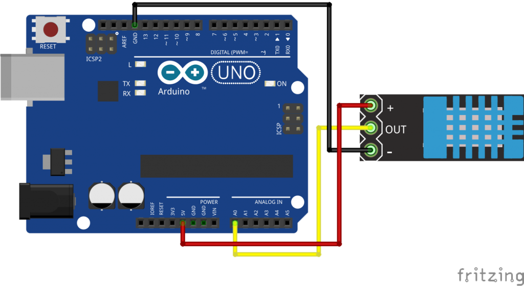
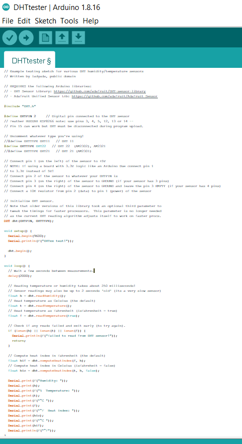
 DHT sensor connection to Arduino Uno.
Before writing the code, make sure to download DHT library for arduino uno.
To download the DHT library clickhere
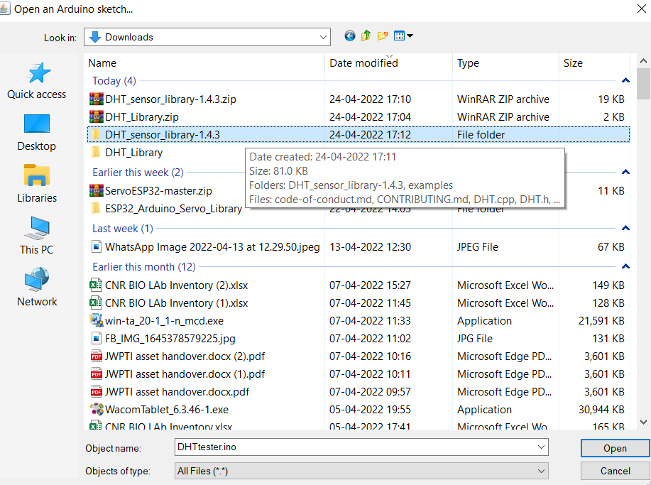
Extract the library and open it on Arduino Ide by clicking on File>> Open
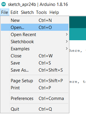
Open the folder where you have extracted the zip file>>
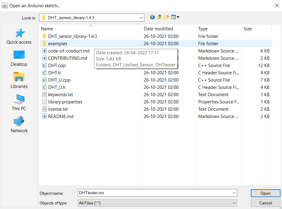
 click on the example folder>>
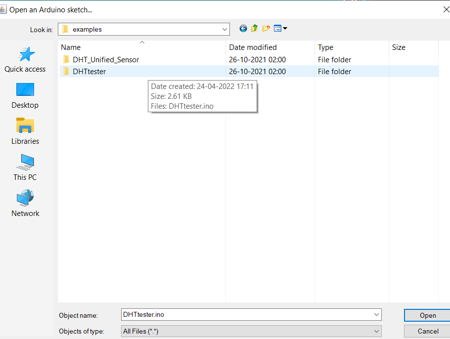
 select the DHTtester folder>>
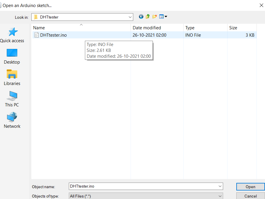
 open the .ino files.
Now modify the data pin connection or connect it according to the example code.
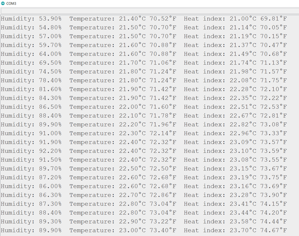
RESULT/ DATA READING of Humidity and temperature.
To see the temperature and humidity differences in the data, I have used two cups of milk coffee placed in a cakebox.
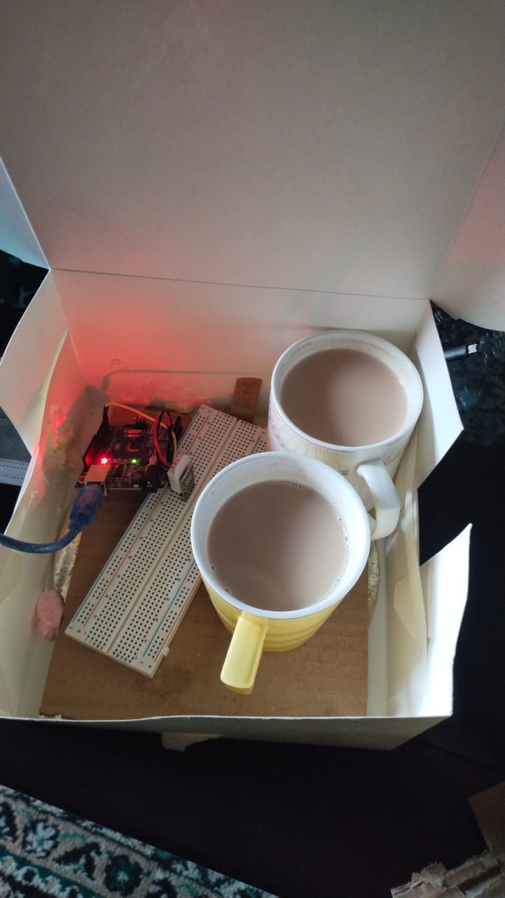
The DATA collected.
USE Self-made ESP32 Board to read DHT data.
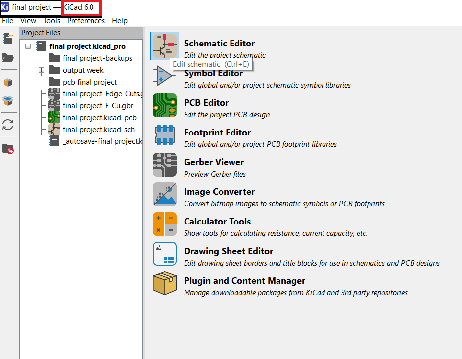
Designing of the Board.
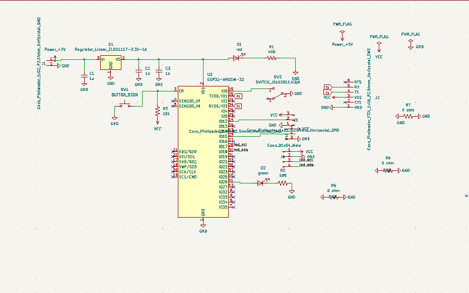
To design the board I have used Kicad. KiCad is a multi-platform, open source software for electronic design which supports schematic entry and PCB layout. As I am using kicad for the first time I refered a Youtube video. You can get the video link from here
To learn kicad in detail refer this video
Schematic design
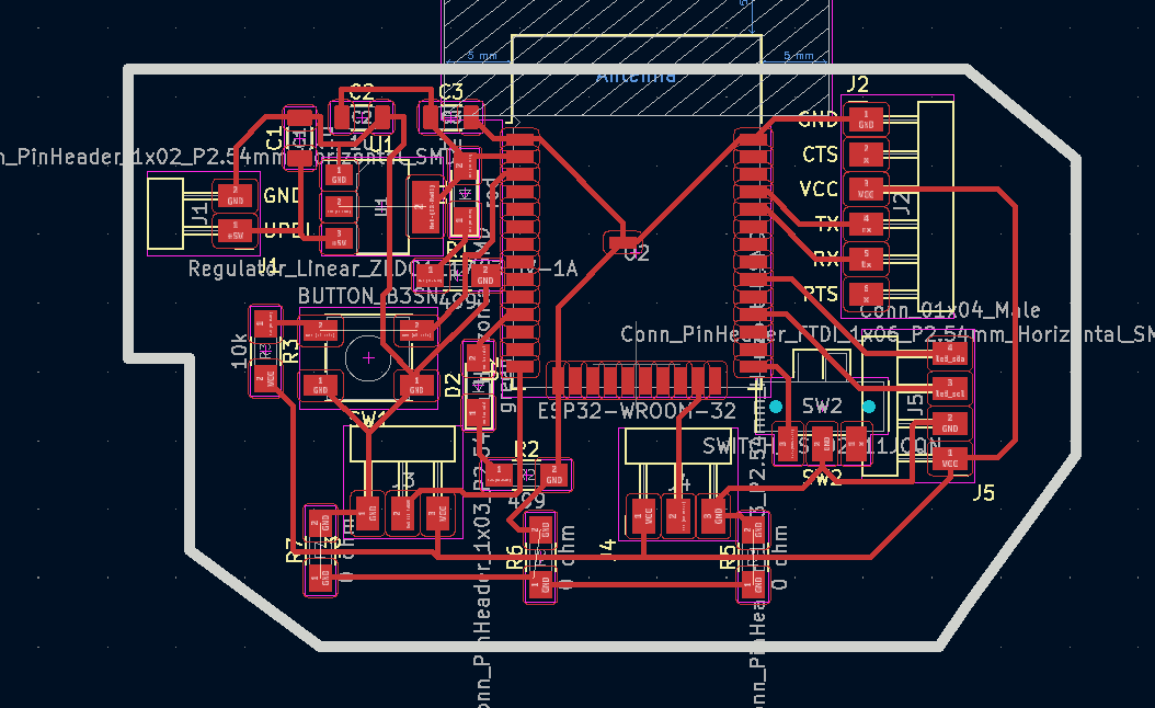
Board Design
PCB Milling
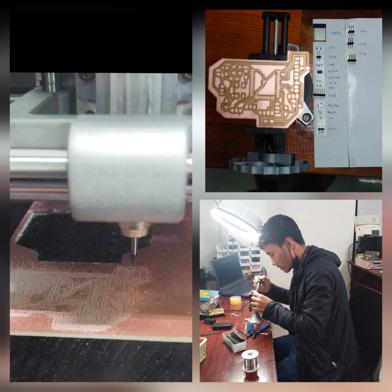
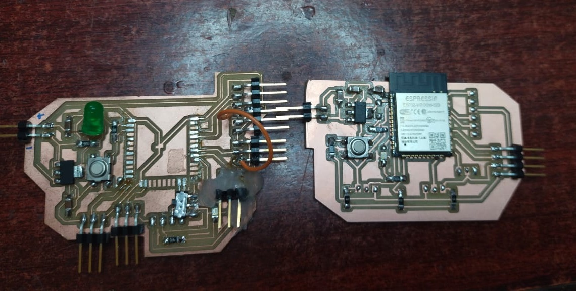
Soldered board

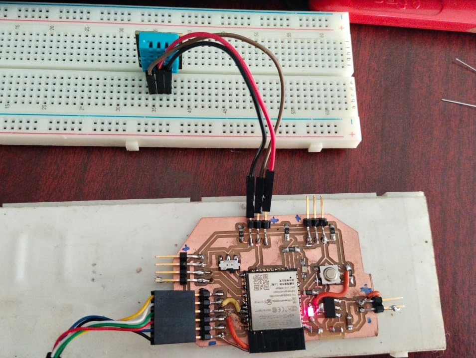
DHT11 sensor as an Input.
Things needed for this connection. 1. self made esp32 board. 2. FTDI connector 3. DHT sensor.
Board connection to DHT
The code:
#include "DHT.h"
//here we use 14 of ESP32 to read data
#define DHTPIN 12
//our sensor is DHT11 type
#define DHTTYPE DHT11
//create an instance of DHT sensor
DHT dht(DHTPIN, DHTTYPE);

void setup()
{
Serial.begin(115200);
Serial.println("DHT11 sensor!");
//call begin to start sensor
dht.begin();
}

void loop() {
//use the functions which are supplied by library.
float h = dht.readHumidity();
// Read temperature as Celsius (the default)
float t = dht.readTemperature();
// Check if any reads failed and exit early (to try again).
if (isnan(h) || isnan(t)) {
Serial.println("Failed to read from DHT sensor!");
return;
}
// print the result to Terminal
Serial.print("Humidity: ");
Serial.print(h);
Serial.print(" %\t");
Serial.print("Temperature: ");
Serial.print(t);
Serial.println(" *C ");
//we delay a little bit for next read
delay(2000);
}
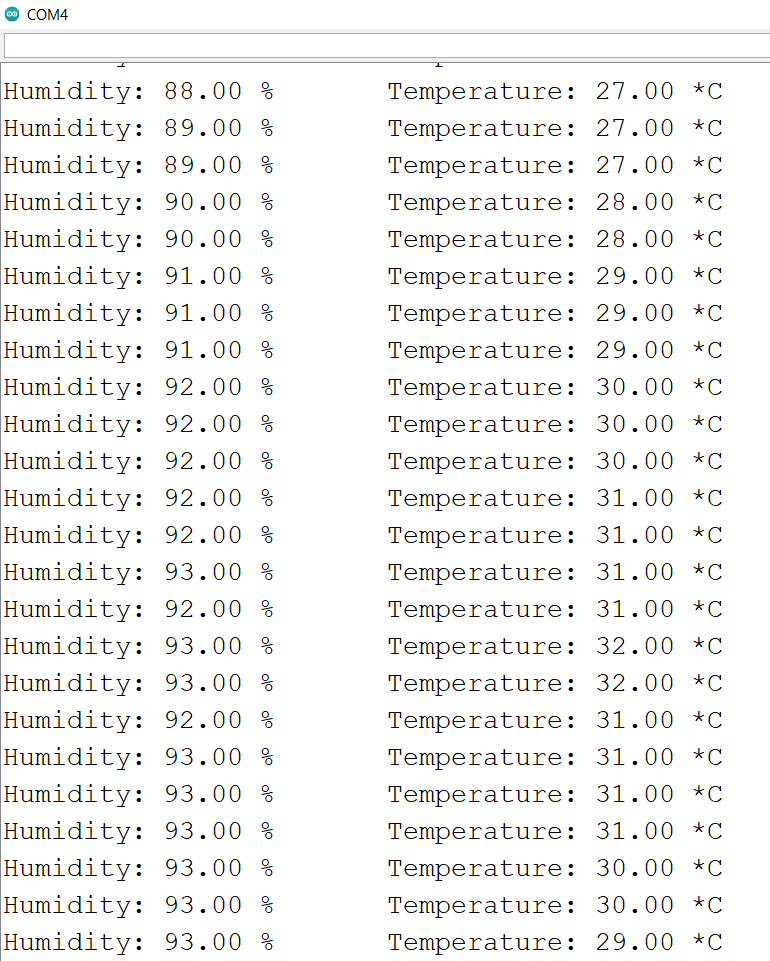
The RESULT AND READINGS.
To see the temperature and humidity reading differences I kept the DHT sensor between my palm and blown air from my mouth and I found this reading.
## Droppler sensor
I have used droppler sensor to detect a motion.
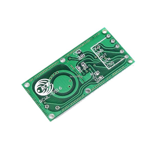
Droppler sensor -can recognize motion via doppler microwave technology with the help of walls or other materials. It will be triggered not only by the presence of people but also by other active objects.
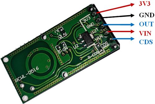
Sensor pinout
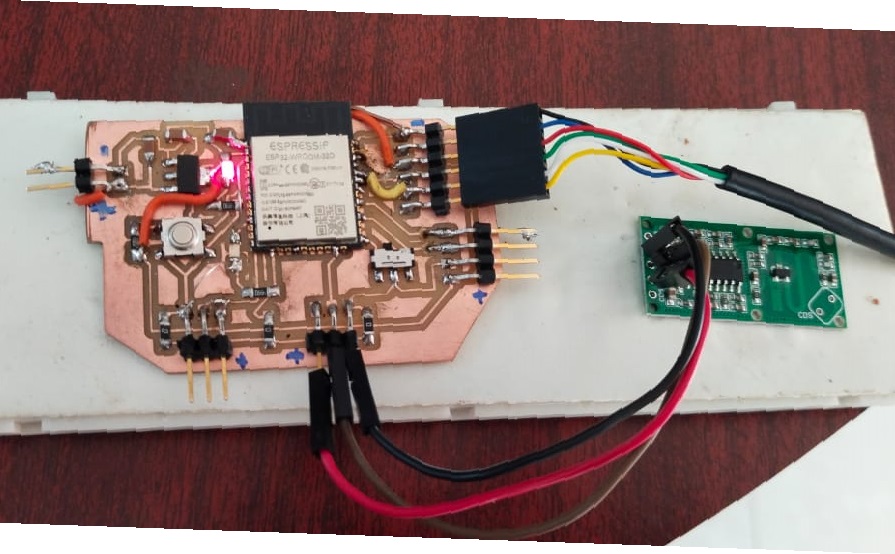
## sensor connection with board
CODE
int Sensor = 15;
int LED = 26;
int flg = 0;  //Change detection flag

void setup() {
  Serial.begin(9600);
  pinMode (Sensor, INPUT);
  pinMode (LED, OUTPUT);
  Serial.println("Waiting for motion");
}

void loop() {
     int val = digitalRead(Sensor); //Read Pin as input
     if((val > 0) && (flg==0))
     {
        digitalWrite(LED, HIGH);
        Serial.println("Motion Detected");
        flg = 1;
     }
     if(val == 0)
     {
        digitalWrite(LED, LOW);
        Serial.println("NO Motion");
        flg = 0;
     }
  }
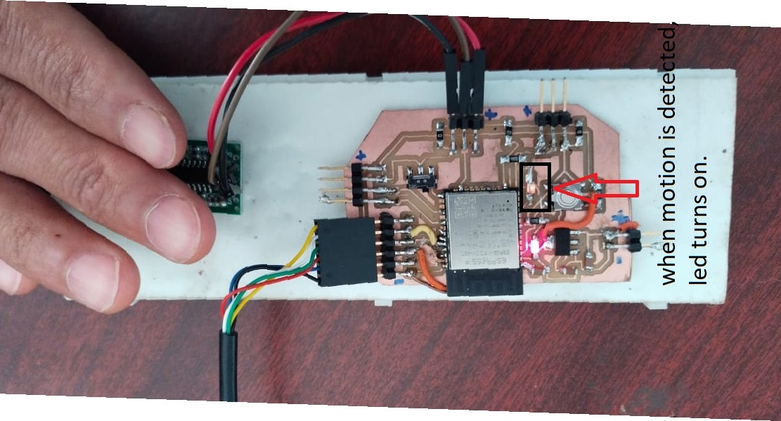
Result
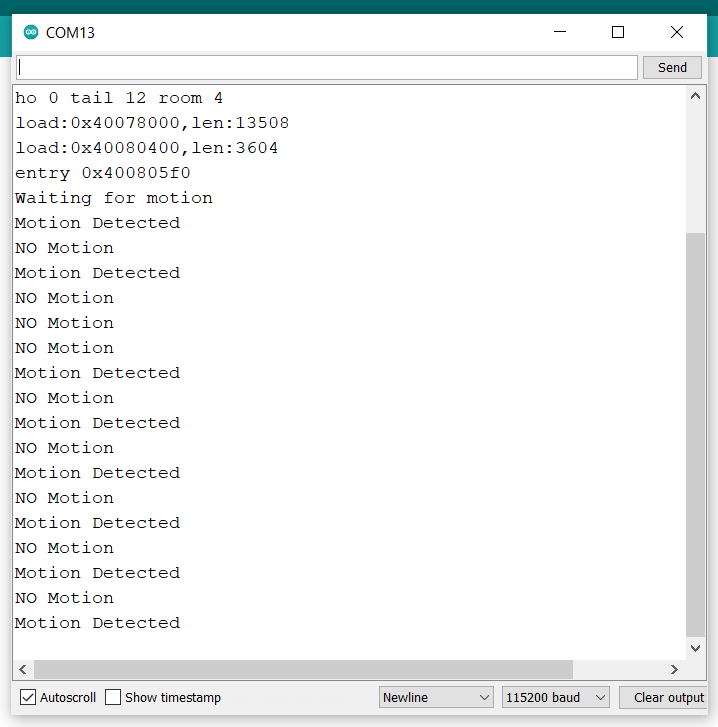
When motion was detected by the droppler sensor, the led connected to GPIO 15 turns on and when there was no motion detected, the led turns off.
Learning Outcomes
- Learnt how to design pcb using kicad
- learnt to use different input sensors.
- Got more familiarize with arduino coding.
Problems and corrections.
- In output and input week I milled the same board twice but with different edge cuts. The ESP32 of the first board got burned and there are few pins left unconnected. I did all the correction and milled a new board. Again there are few pins left unconnected but I used jumper wires to make the necessary correction. I changed all the nessary corrections in my schematic and board design in kicad. I will mill the corrected board for my final project.
## Original files.
Download all the original files from here.