4. Computer controlled cutting
Group Assignment:
Q. Characterize your lasercutter’s focus, power, speed, rate, kerf, joint clearance and types.
For the Group Assignment refer this LINK
Individual assignment:
Cut something on the vinylcutter, Design, lasercut, and document a parametric construction kit, accounting for the lasercutter kerf,which can be assembled in multiple ways,and for extra credit include elements that aren’t flat.
Vinyl cutter:
A vinyl cutter is a type of computer controlled machine.It works like the traditional printer where it receives data from a source and prints images onto a paper. The only difference is instead of having ink reproducing your work onto paper it relies on small blade to cut the pattern of image into the vinyl or other materials.
Uses of Vinyl Cutter
Some of the things you can make with a vinyl cutter at home include:
-Labels and stickers -Vinyl decals for wallpaper, smartphones, and -laptops -Letters -Decals -Banners -T-shirts and apparel decoration -Cards -3D objects -Origami
Applications.
Most craft businesses invest on the best vinyl cutter for different purposes, which includes: -Advertisements -Signage Businesses -Clothing and Accessories -Home décor, etc..
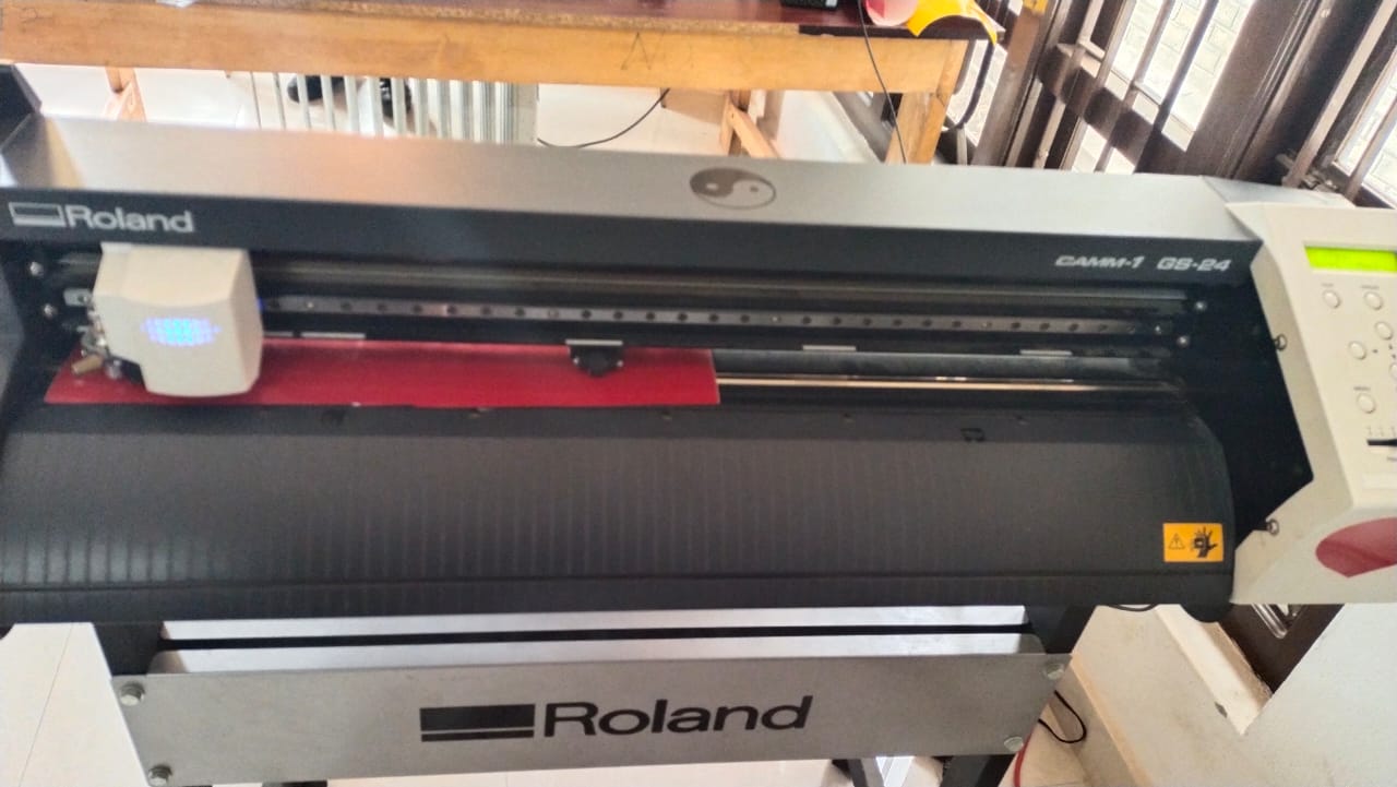
Machine used: Ronald CAMM-1 GS-24.
Learn more about the machine HERE.
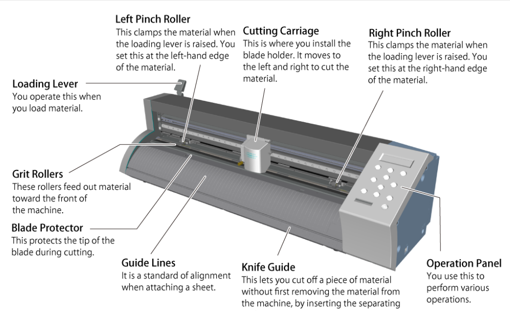
Parts Name of Ronald CAMM-1 GS-24
Front
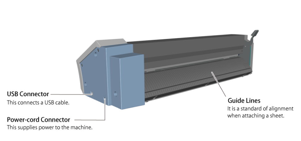
Back
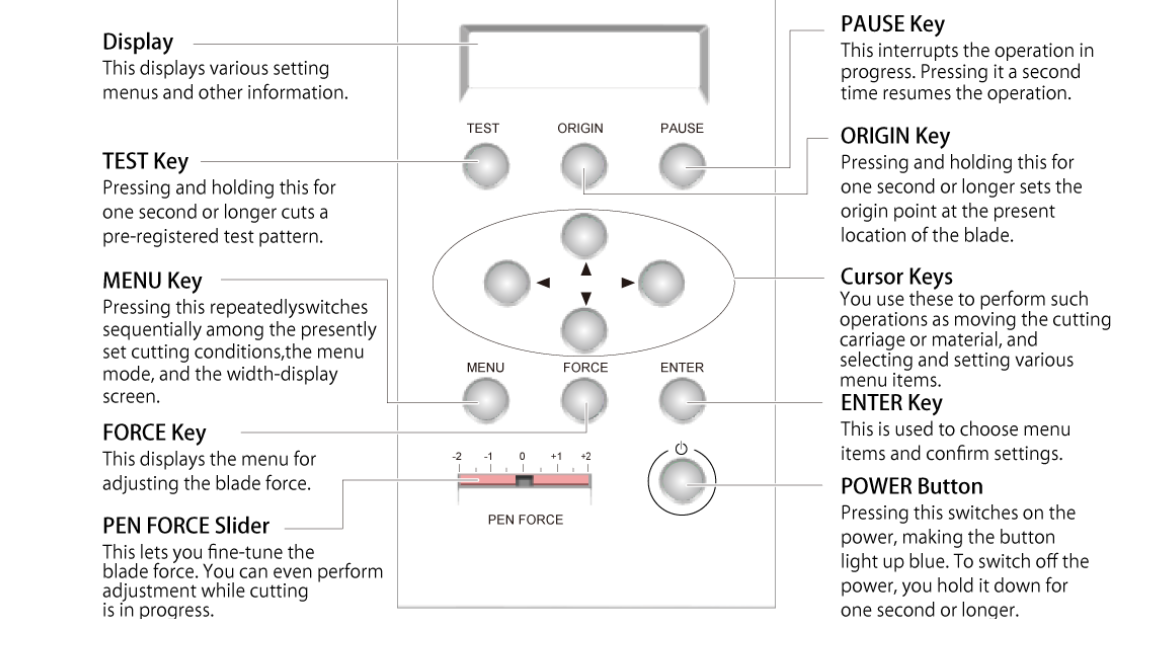
Operating Panel
How to Use the Machine.
Items required other than the machine are: 1. Computer with Software (CutStudio) installed. 2. Material (210*298mm/A4)
Procedure to Operate the Machine.
Refer the user manual to operate the machine here
OR
Refer here
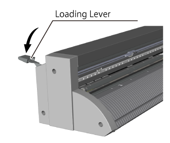
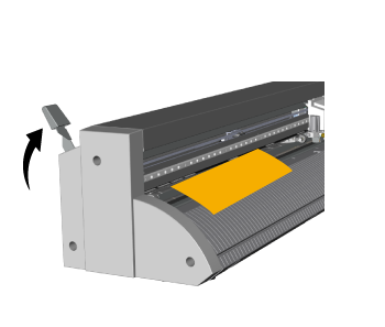
Step 1: Load the Material Procedure 1. Lower the loading lever
- Load the material
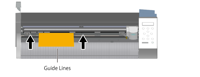
- Set the material in the position shown in the figure below.
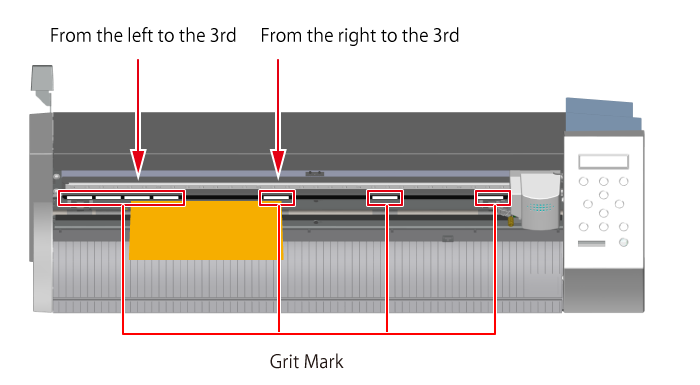
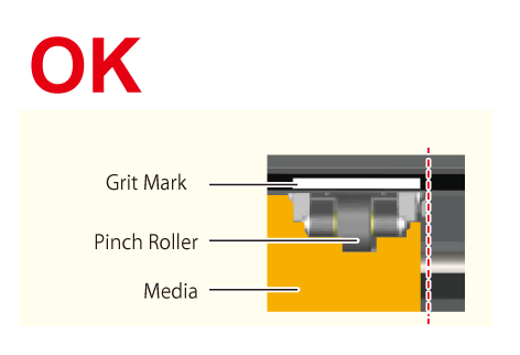
- Move the pinch rollers to the edges of the material so that each one is within the grit marks.
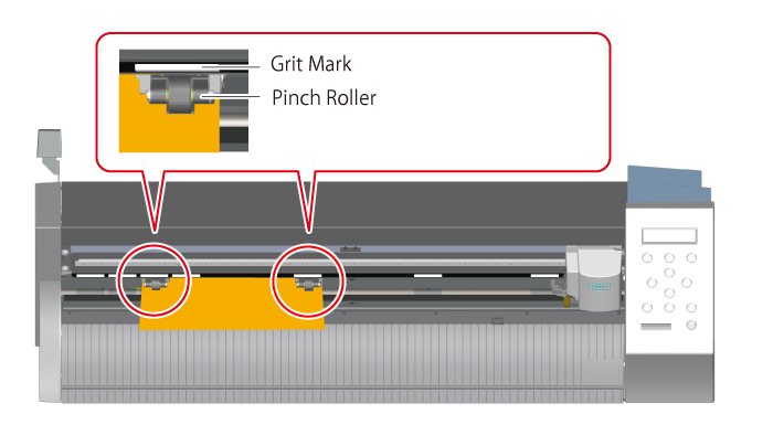
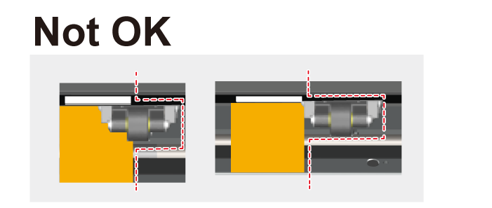
The pinch rollers must not extend beyond the grit marks
GOOD
NOT GOOD
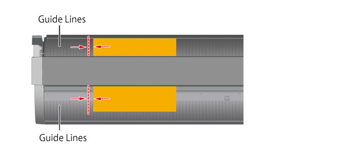
- Align the left edge of the material so that it lies approximately parallel to the guide lines.
- Raise the loading lever
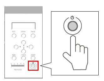
Step 2: Turn on the Machine Procedure 1. Press the power button
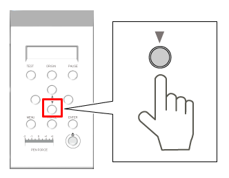
- Press , and select PIECE.
- Press MENU
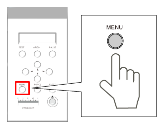
Make sure the values for the items are displayed as shown in the figure. For Example ;
Step 3: Prepare the Blade
Things required
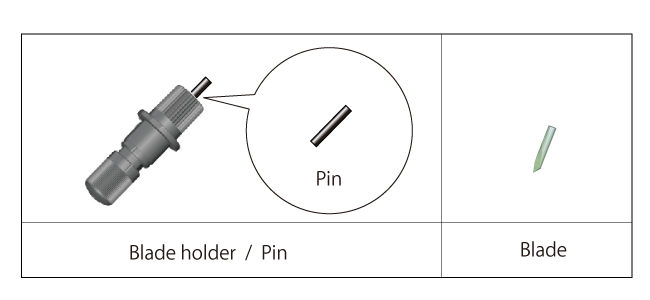
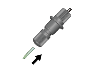
Procedure 1. Insert the blade.
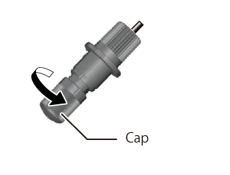
- Rotate the blade holder cap clockwise and tighten it until it stops.
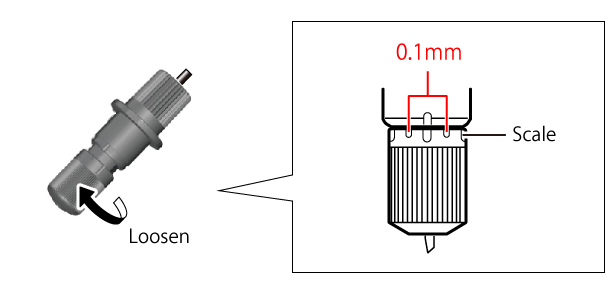
- Adjust the amount of blade extension according to the material.
- Install the Blade Holder by loosing the cutting carraige screw shown in the figure.
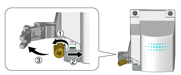
-
Tighten the screw.
-
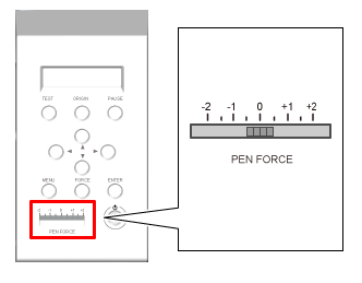
Perform a cut test. Before the test make sure the PEN FORCE slider is at 0 on the scale.
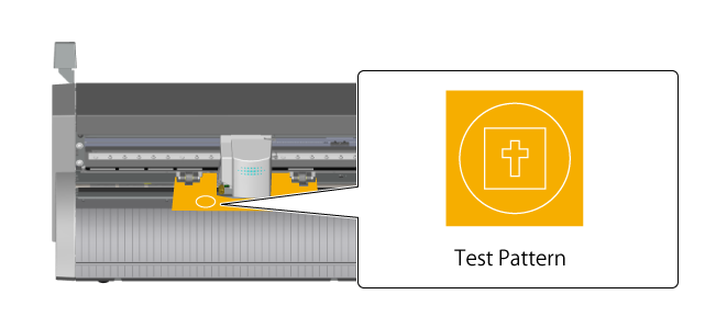
- Press the TEST key for a second or longer until the test pattern is cut.
- Press the downward button to feed the material forward. Then Peel off the circle with a tweezer.
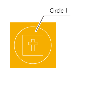
- If circle peels off alone , then peel off rectangle. Otherwise change the blade force.

If the blade didn’t cut through the material’s carrier paper move to the next step otherwise ‘change the blade force.’
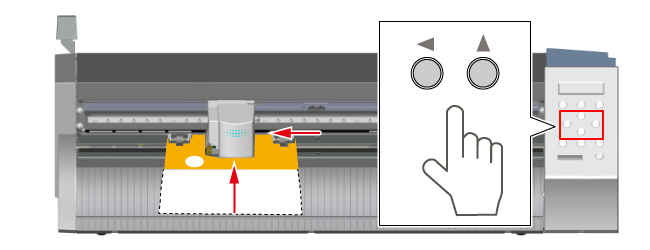
Step 4: Set the Origin
Procedure 1. Press 4 direction button to move the cutting carriage to the location you want to set as the origin.
- Press ORIGIN for a second or longer until the display flashes.
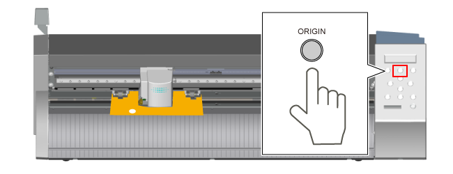
ORIGIN is SET. Now your printer is ready for printing.
How to Create Cutting Data?
Software used: Inkscape and cutStudio.
Install Inkscape form Here
Install CutStudio software from Here
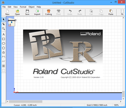
For me the lab has already installed the cutstudio software and it’s ready to use.
If you don’t know how to setup the software for the printer refer this link
Cut something on the vinylcutter
cutting stickers on vinyl?
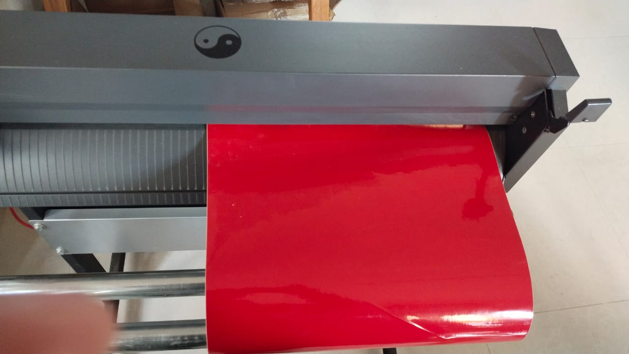
Selected the material sheet on which I wanted to print my sticker, released the loading leveler and manually loaded through the Grit Roller.
After that leveler is locked into the position. Then the origin was set from where I wanted to start printing using the button.
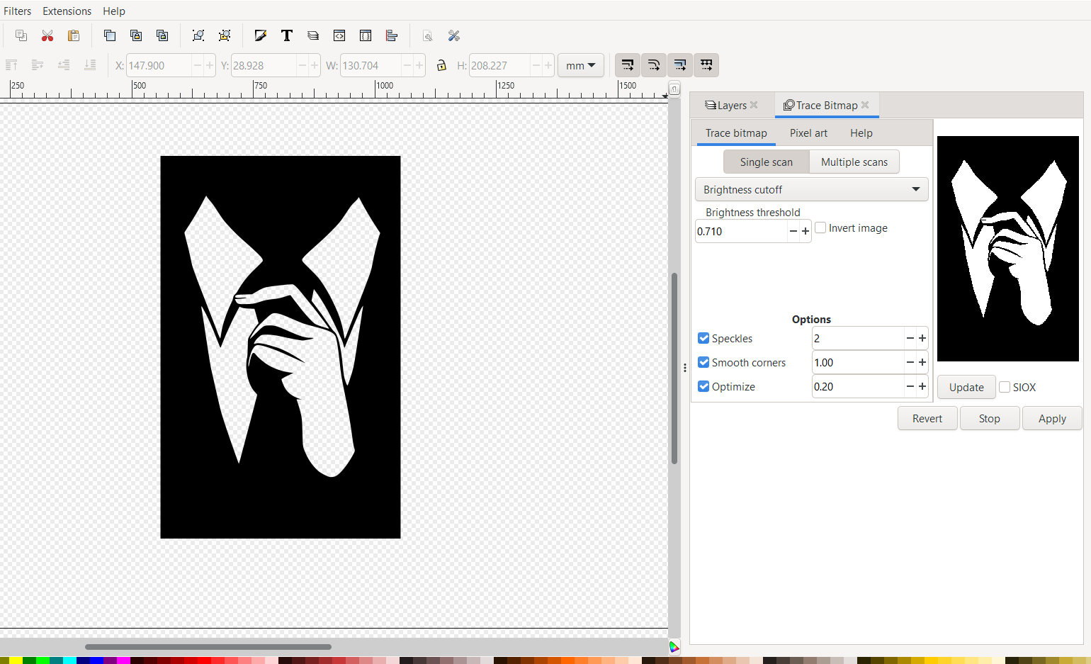
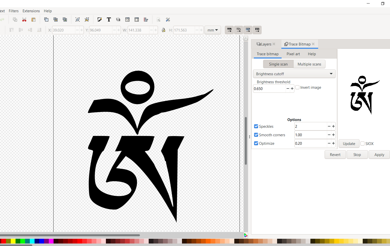
Now I downloaded a black white image on my desktop and opened on inkscape, vectorized the image using Trace bitmap and saved the image in Plain SVG file.
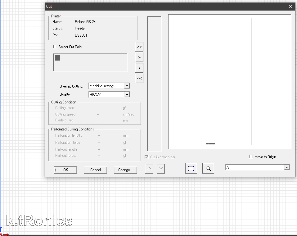
Then, opened cutStudio software which was the software connected to cutter. Loaded my sticker and selected image outline. Checked machine setting and clicked on cut.
Once the cutting is over, then the unwanted material was removed using tweezer.
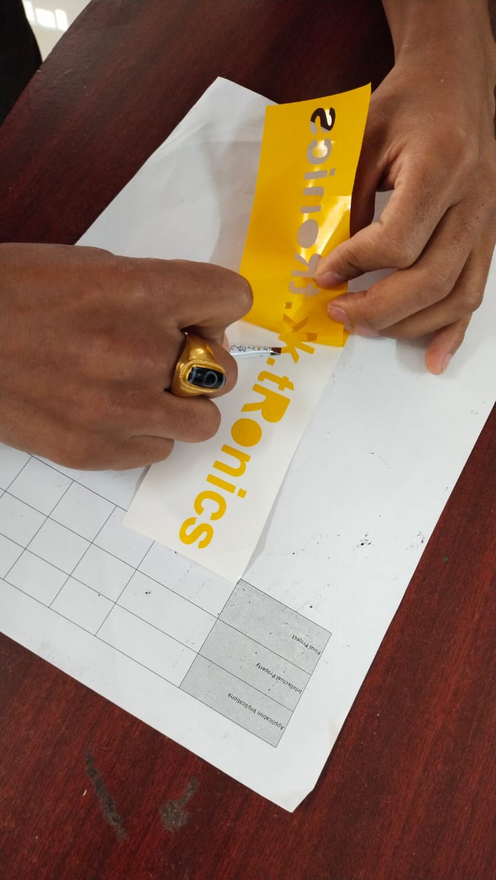
Next, I pulled the parts of sticker that I wanted using tape and pressed it down on the desired location.
My final result
Working with Laser Cutter
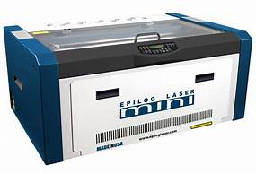
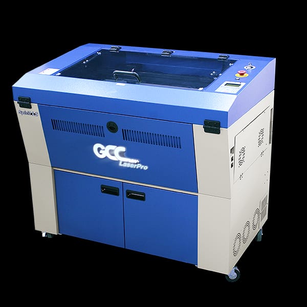
Machine available in lab: Epilog Laser mini and GCC laser pro
Machine used: GCC laser pro
Softwares used: CorelDraw, DXF for laser, Fusion360.
What is Laser cutting?
Laser cutting is the process of using lasers to cut different materials for both industrial and non industrial purposes. It uses a high-power laser which is directed through optics and computer numerical control (CNC) to direct the beam or material. Typically, the process uses a motion control system to follow a CNC or G-code of the pattern that is to be cut onto the material. The focused laser beam burns, melts, vaporises or is blown away by a jet of gas to leave a high-quality surface finished edge.
If you wanted to learn how to operate the EPILOG LASER mini refer this link.
Parametric Design and Laser Cutting.
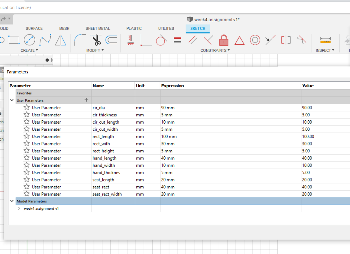
For the parametric designing I used fusion 360. Modeling using parameters is called parametric designing. The advantage of parametric design is that we can modify or change the design anytime by changing parameters.
PressFit Kit
PressFit means joining two or more shapes with the notches made on parts without using any glues.
Let me give a quick review of what I have designed in this week using fusion 369 to make a PressFit parametric design.
This is my second week using fusion 360.
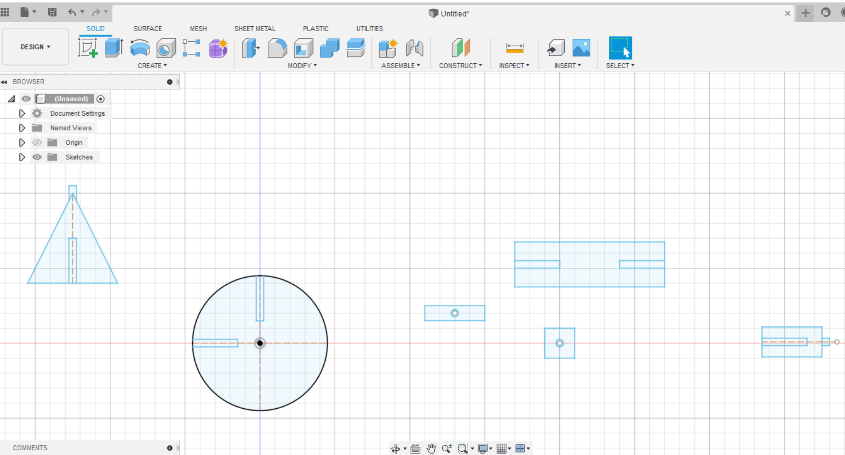
I started to brainstorm what I wanted to design. I came up with a simple idea of making a bicycle. Then I started setting parameters for different parts of the bicycle as show below.
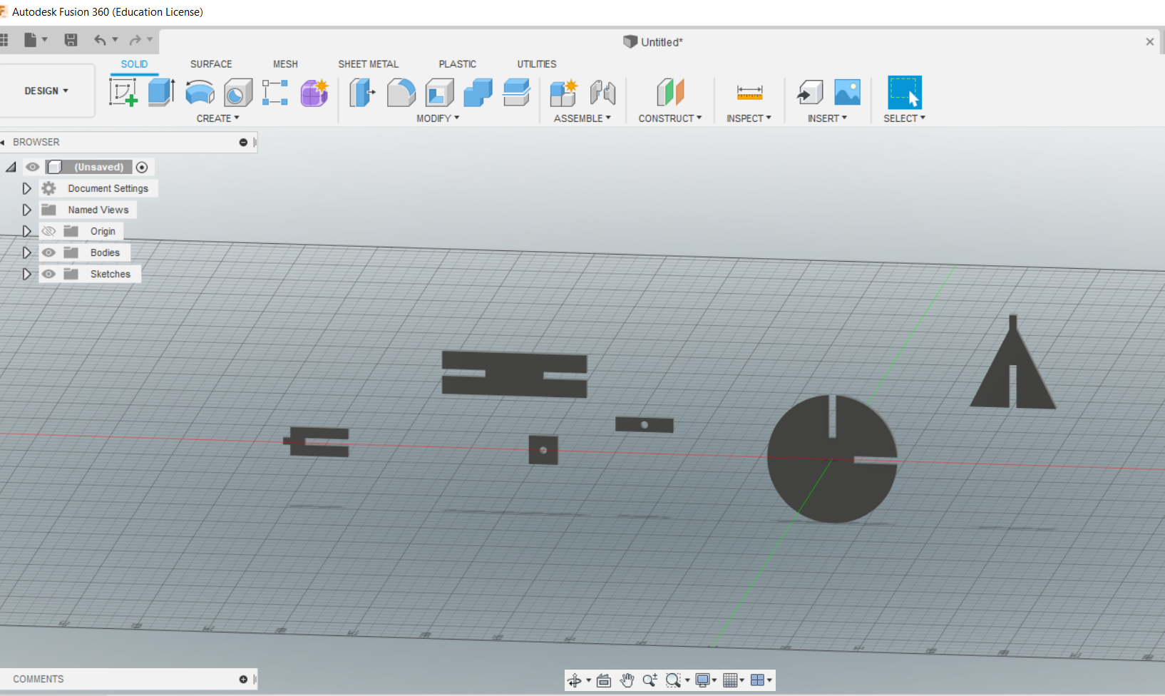
Then I sketched the different parts of bicycle in 2D. Once I finished my sketch, I extruded them as per the thickness of the material I am going to use.(5mm in my case as I am using cardboard).
After completion of the design, I exported them into .dxf file and opened in coral draw which was the connected software to Lasser cutter.
Once the pieces were cut I assembled to make the bicycle.
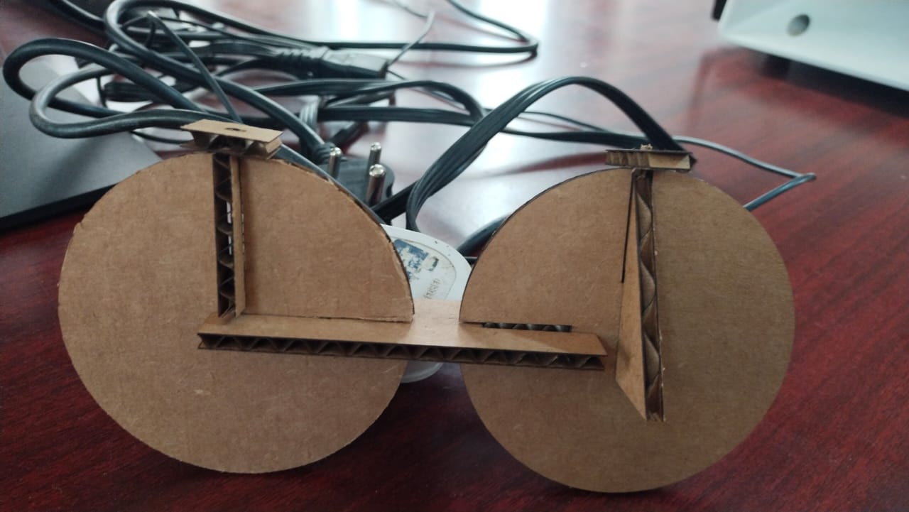
Failed! as you can see my bicycle wheel is too big and the PressFit cut depth was way inside eachother.
But the best thing of parametric design is I can change my parameters anytime. So, In this case I reduced circle diameter from 90mm to 60mm and PressFit cut depth to 15mm from 30mm.
And one more interesting thing that I have learnt in fusion 369 is I can assemble my parts to checkout it’s result before printing.
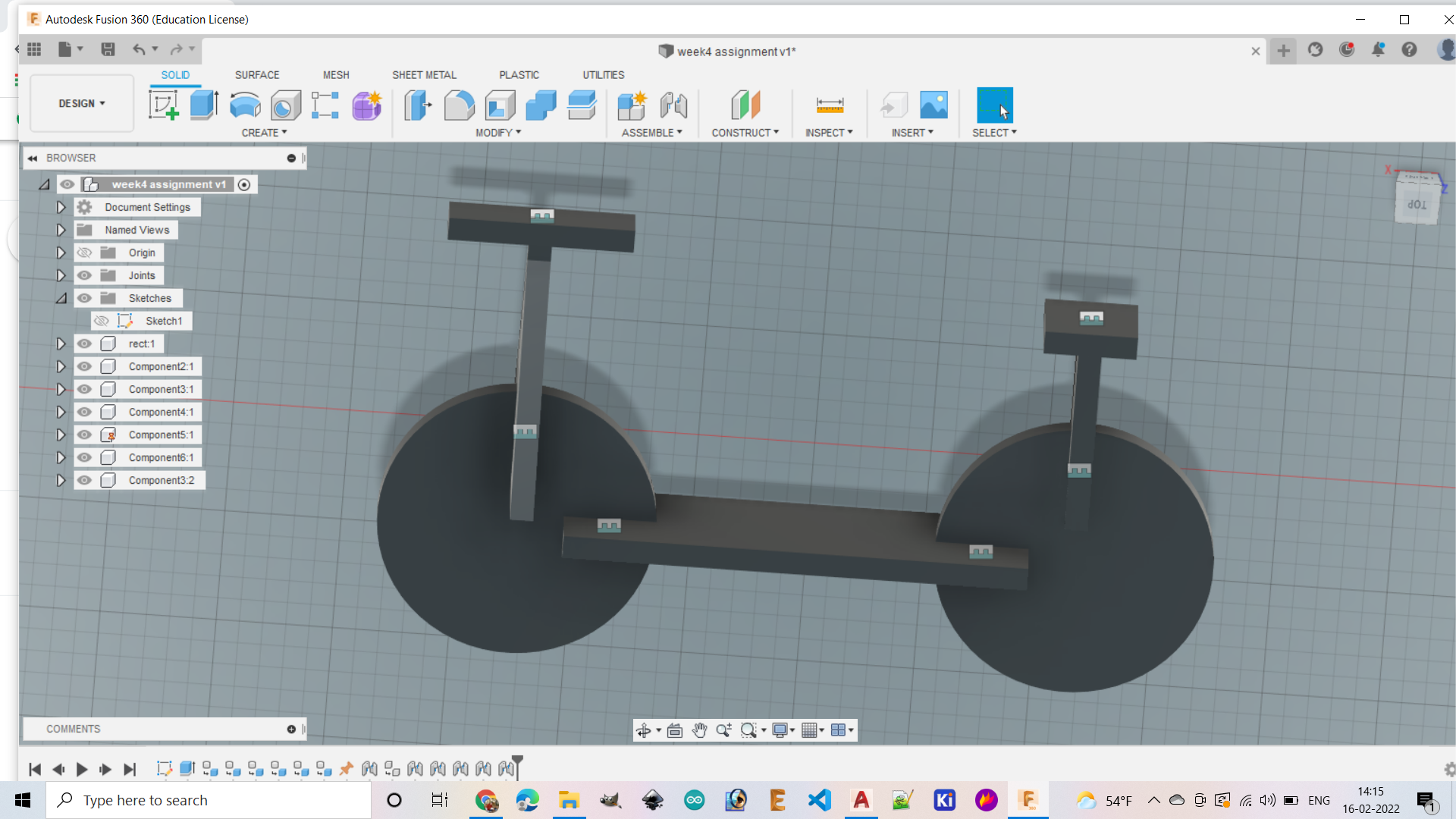
After I cross checked and modified all parameters I laser cut the bicycle parts again and this time it was successful.
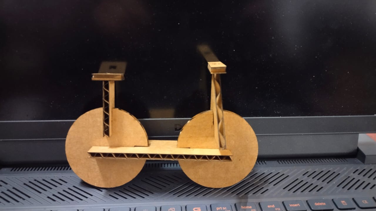 Does it really looks like a bicycle?? lol
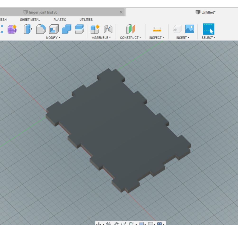
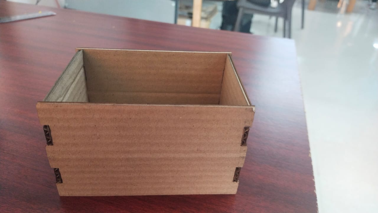
Finger joint design.
- For the finger joint design, I drew a rectangle of 120mm X 80mm on fusion 360.
- Then I used rectangle tool to make a finger on both side of the rectangle of 15mm X 5mm which is protuded outside.
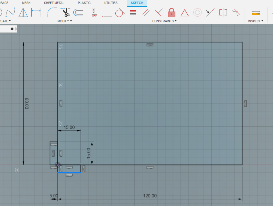
- Then I have used rectangler pattern from create option to duplicate the fingers on each side as per my need.
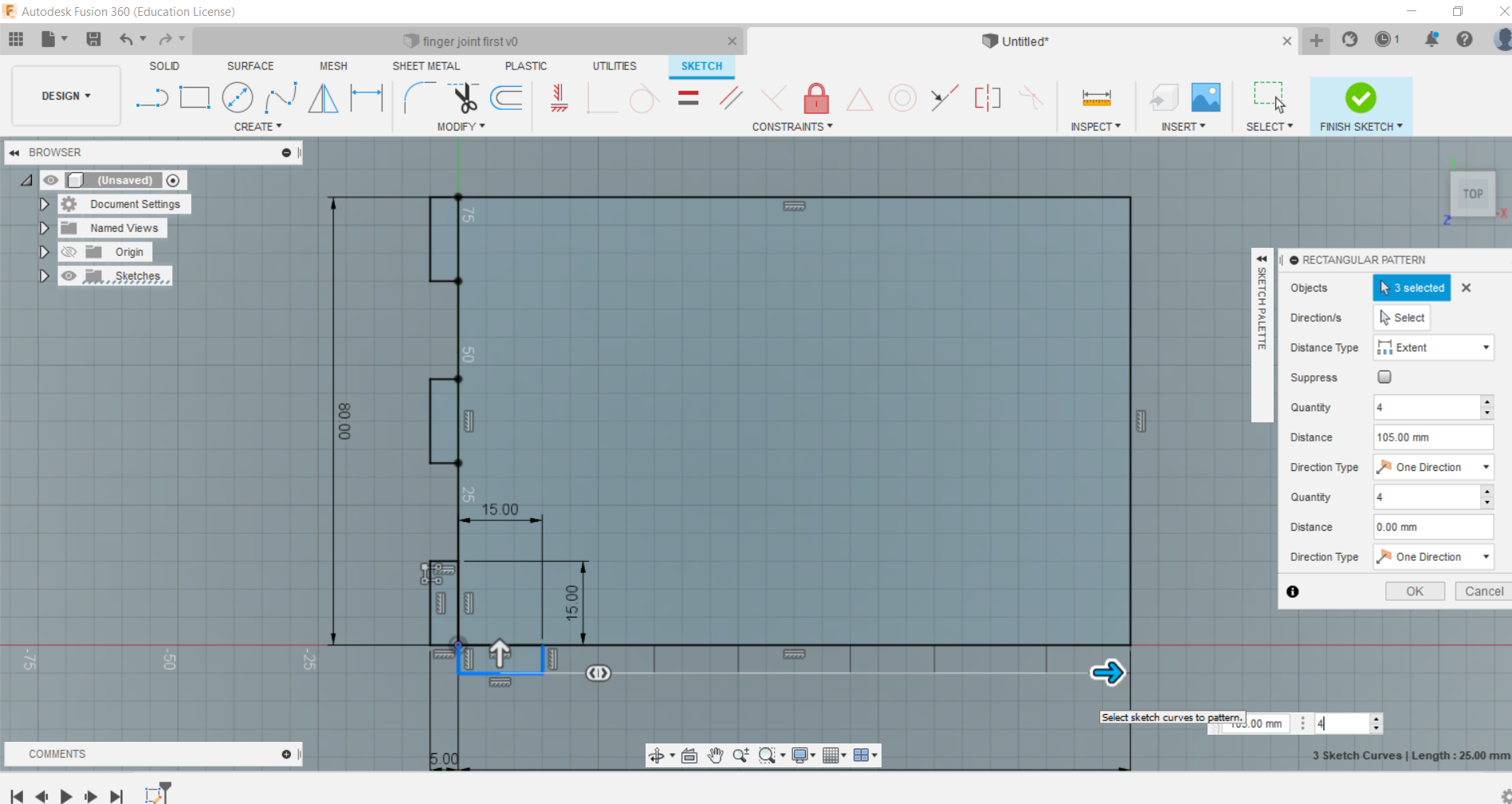
- Then I used the mirror tool to mirror the fingers on opposite side of the rectangle.
- Before mirroring the the fingers, make mirror line by dividing the each side of rectangle into two equal halves.
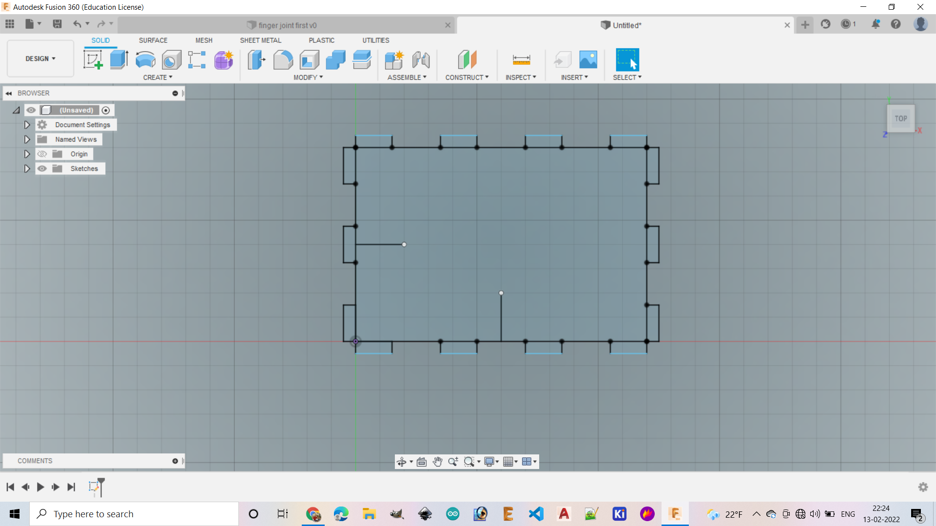
- Then I extruded the design through 5mm as I am going to use a 5mm thick plywood.
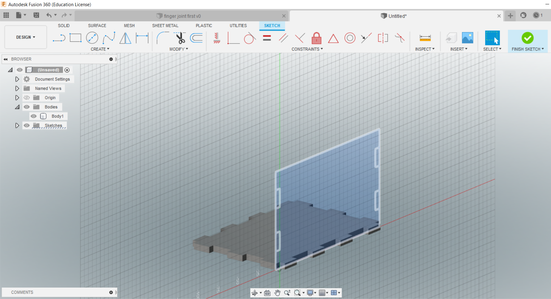
- After that I have selected a planner face to start designing the side wall of the box.
- Then I made fingers on each side of the wall using the tools I have mentioned above. Extruded the side and made a copy for other side of the box.
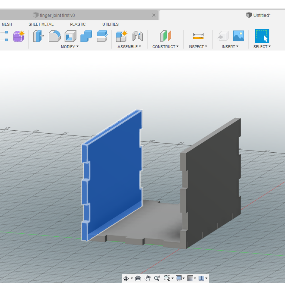
- Then made face of other side of the box and made the fingers taking the references of the previous face of the box so, that it can fit well later.
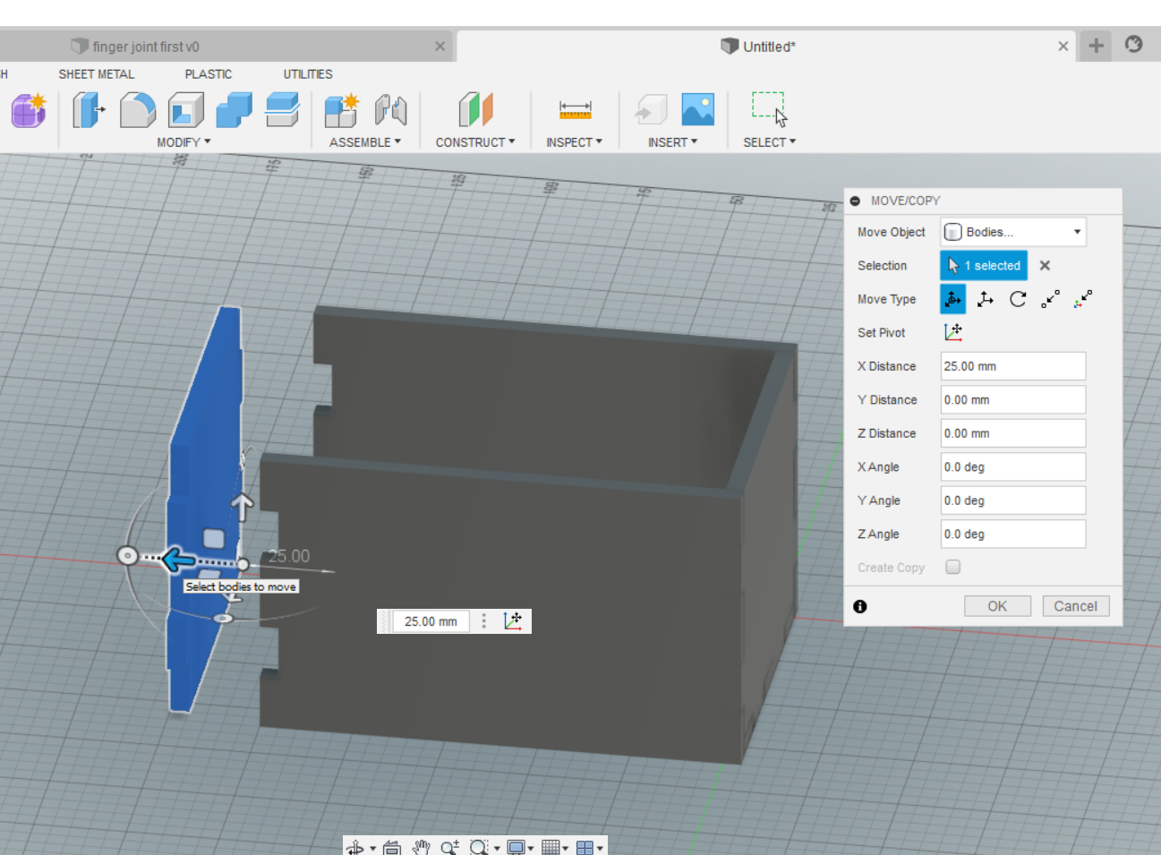
- After that extruded and move the face by making a copy of it to the opposite side.
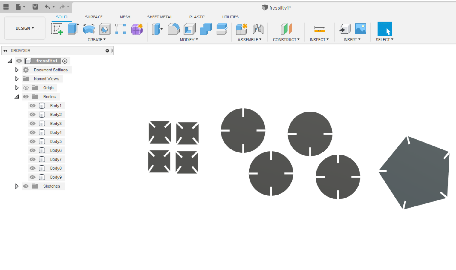
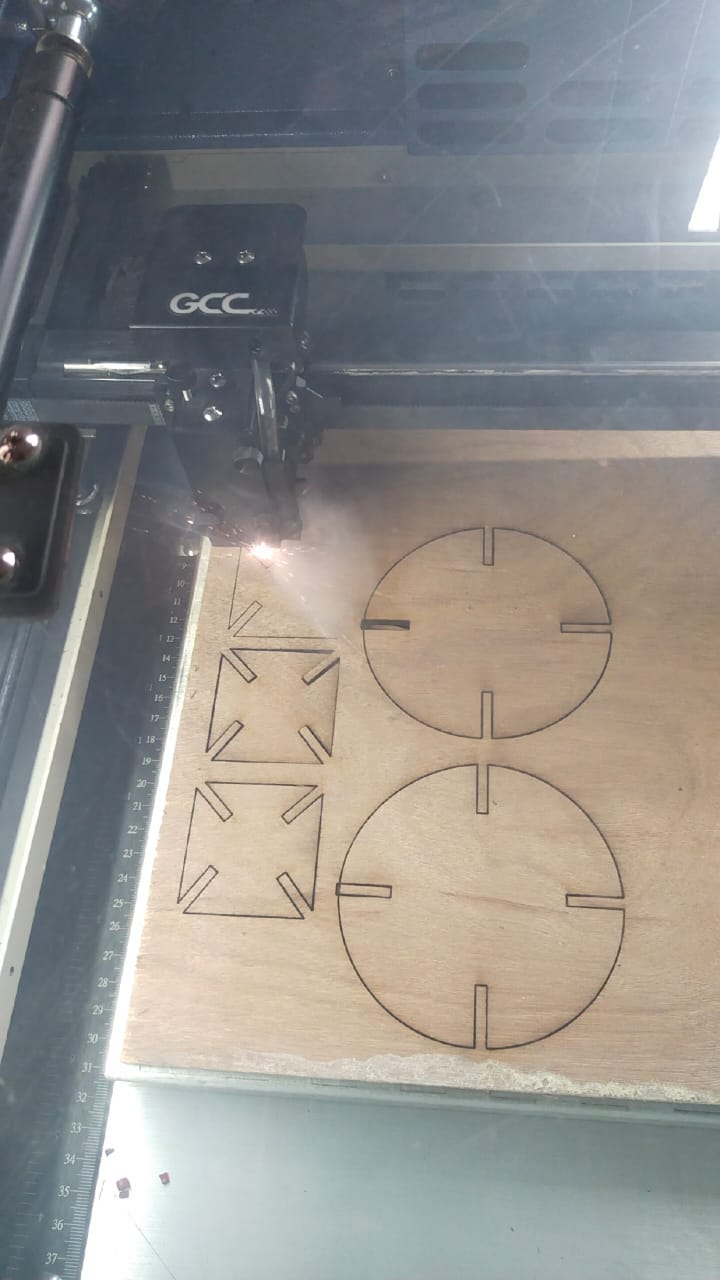
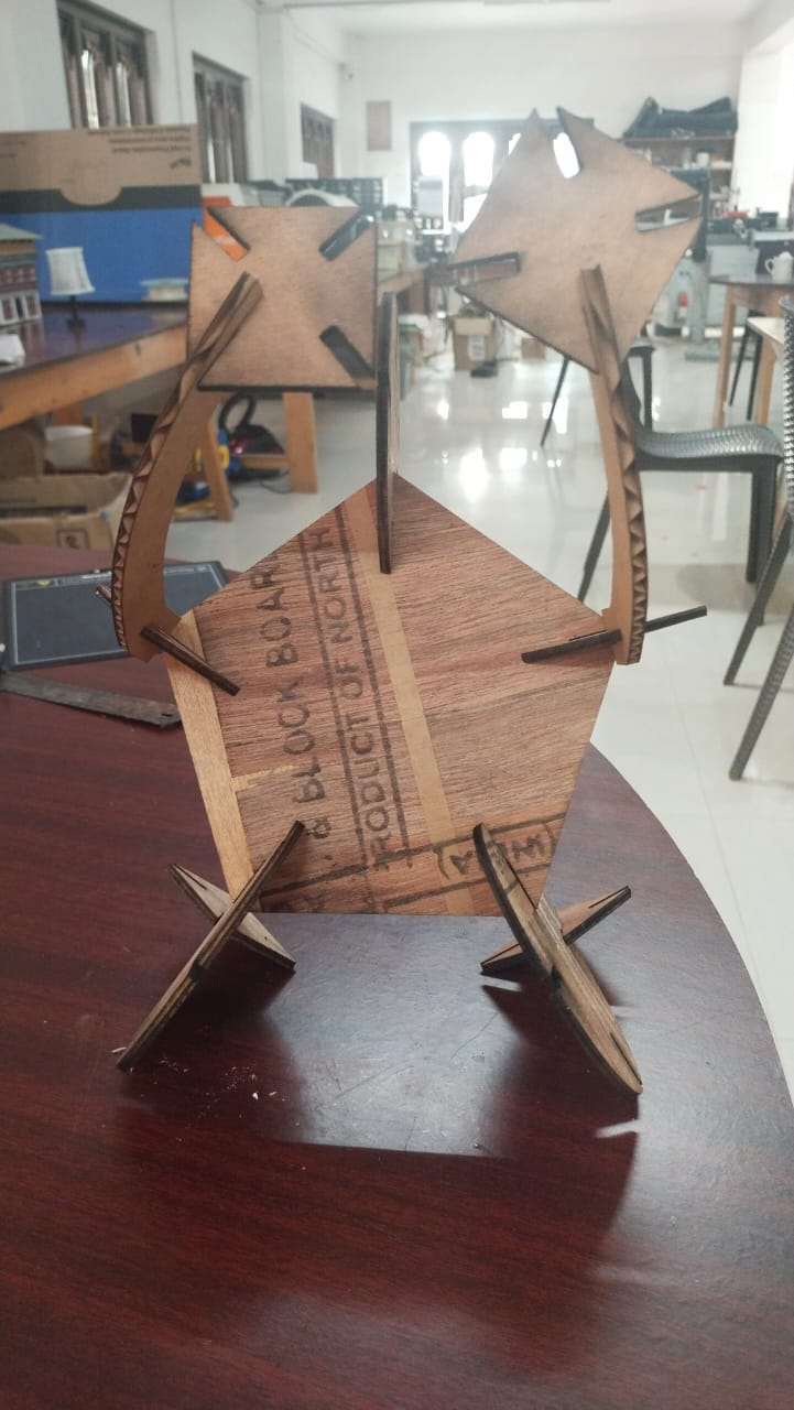
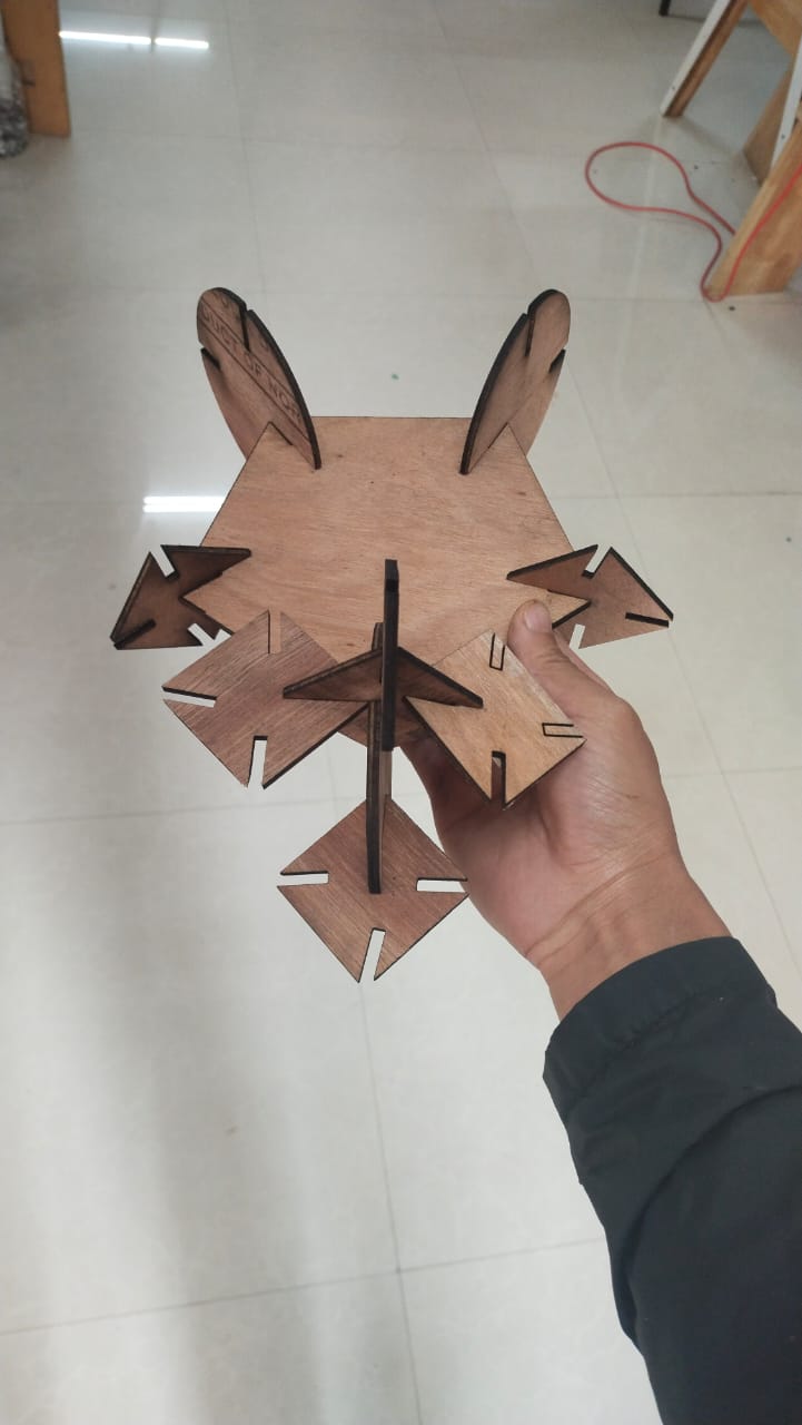
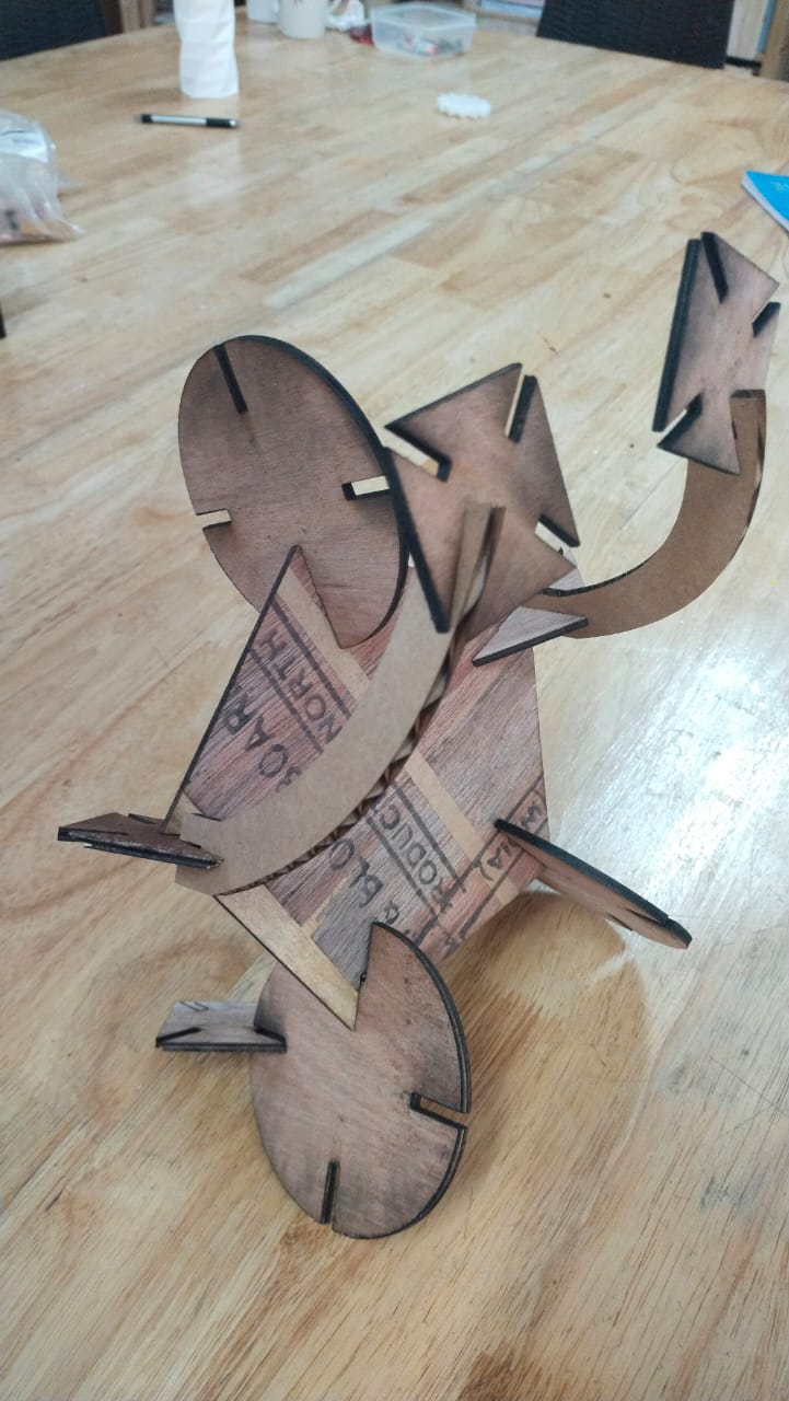
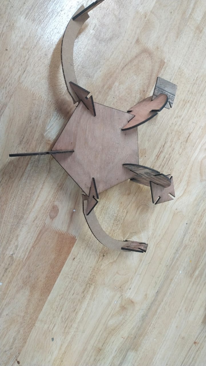
Design something that can be assembled in multiple forms.
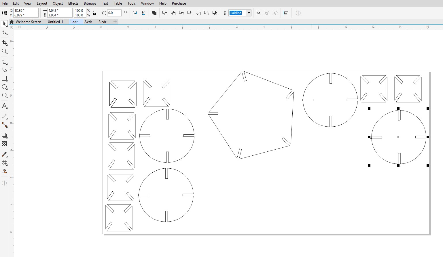
For that I have used fusion 360 to design some square, circle, and polygone shape with kerfs which I can later use to assemble into different shapes.
Make Design files for laser cutting
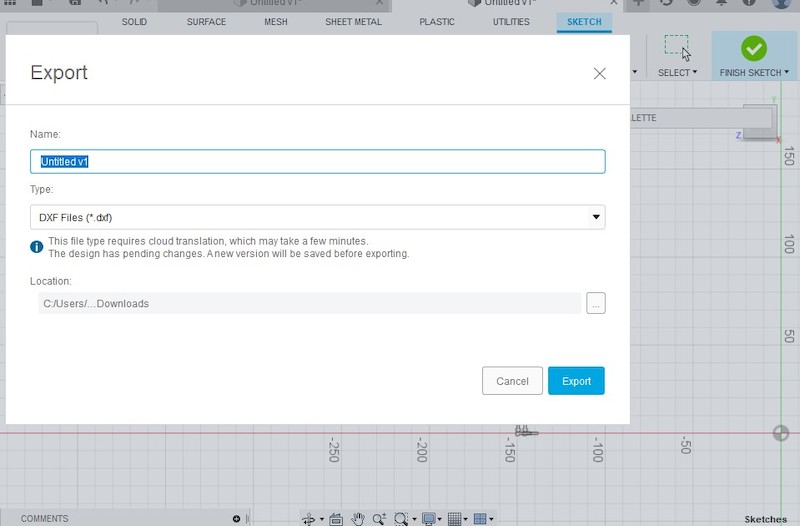
Once the design is finished I exported the design in dxf file.
Then I opened the file in CorelDraw but the file opened with error. It opened with some lines, not the design.
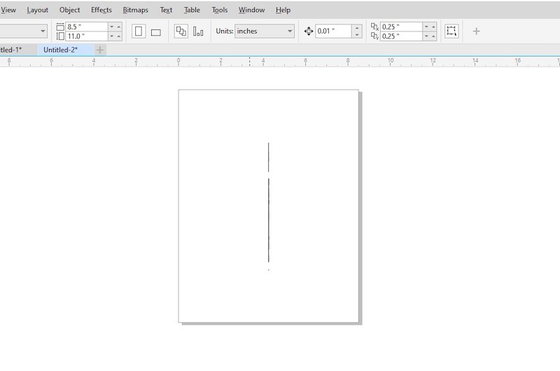
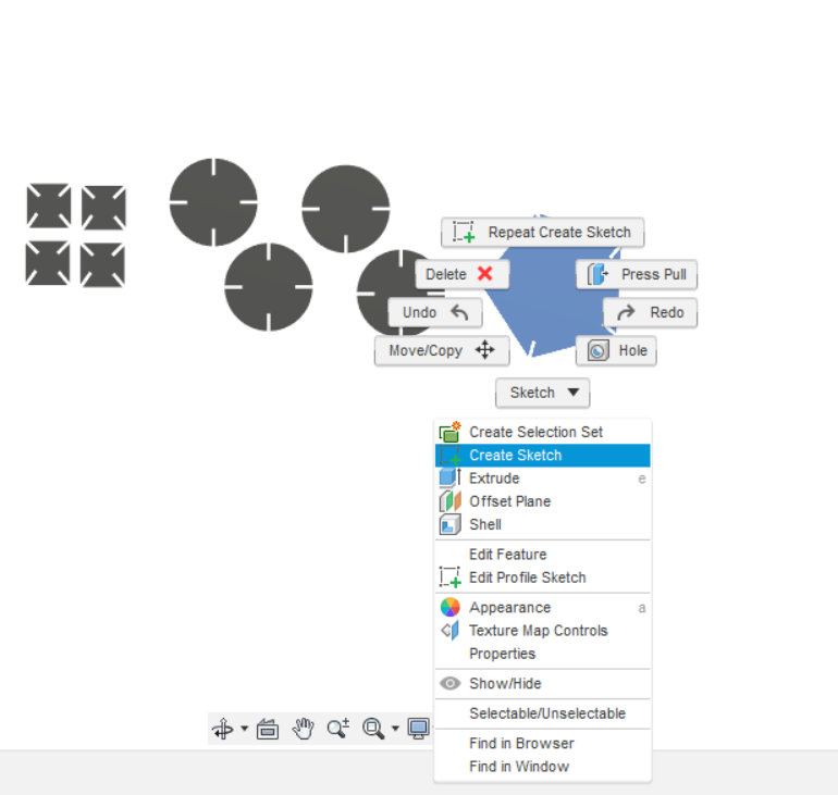
Later I learned that we have to create sketch of the design and then save them as DXF.
To create Sketch and save file as Dxf click on the design > right click > create sketch.
Then select the sketch and click on save as dxf.
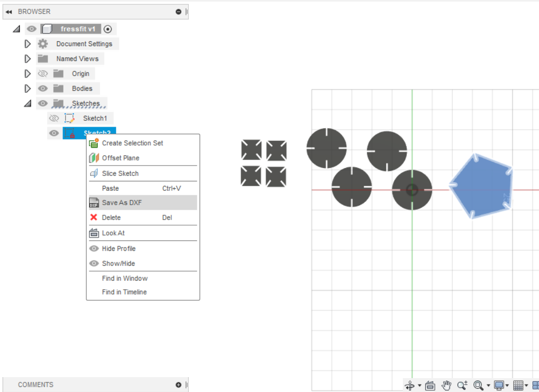
Repeat the same process for every design.
Now open the Dxf file on coraldraw and arrange them according to the material place in the laser bed.
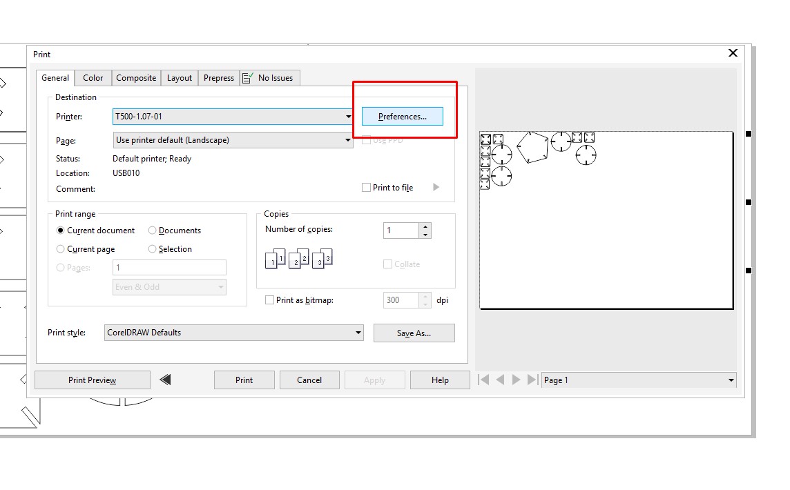
Select all and Press ctrl+p on keyboard to make the file ready to print. New window will pop up, click on the preferences.
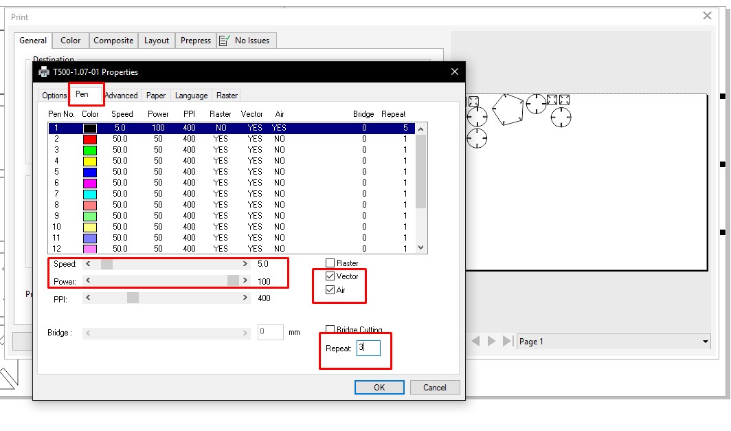
Then clcik on Pen from the menu and choose the power, speed deselect raster, and select vector and air. Then set the numbers of repeats.
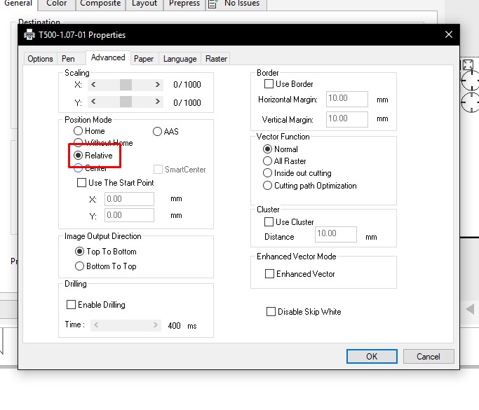
Next click on Advance from the menu and select relative for the position mode.
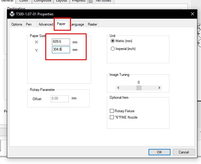
To set the paper size click on paper and make X= 609.6 and Y= 304.8mm.
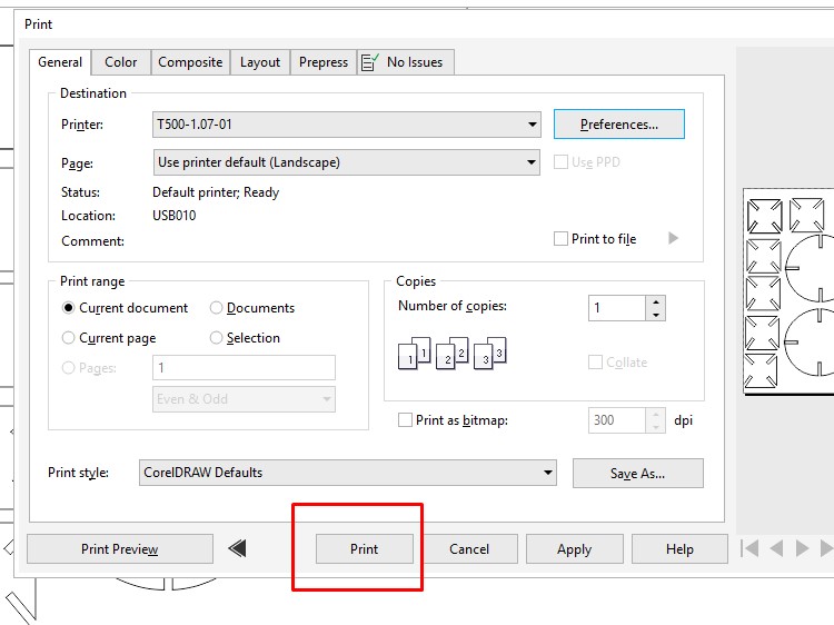
After making all the setting ready click on the print button.
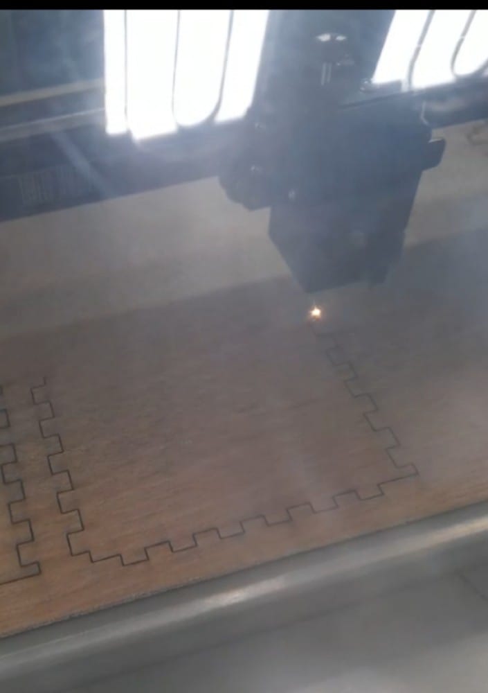
Laser cutting.
Now the file from the desktop will appear on the screen of the laser. Set the origin using x,y,and z button and press enter to initiate laser cutting.
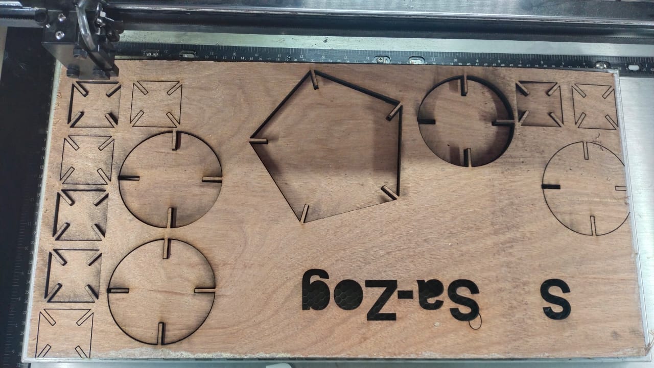
FINAL RESULT
Learning Outcomes
- learnt how to operate Ronald CAMM-1 GS-24
- Learnt different features of cutstudio, Inkscape, Coraldraw softwares.
- Learnt how to operate Laser cutter
- Learnt how to prepare files for differnt cnc machine.
ORIGINAL FILES
Thank You