15. Mechanical design, Machine Design
PET BOTTLE TO 3D-printer FILAMENT
Group B-Positive
B positive! The group B from Fablab Mandela are also working with Fran and Sibu to set up 4 fablabs in Bhutan and attending the fabzero course as well. After coming back from setting the fablab in Punakha, all the members of Group B along with Fran and sibu tested positive for Covid19 (to be very specific the omnicorn variant). So we were advised to home quarantine for 1 week. Hence the name of the group was formed: “B-positive” - Group B of the fablab mandela who were all tested positive for covid 19. We are the B-positive group
INTRODUCTION
While brainstorming as a group what to do for machine design and making, we decided that we wanted to make a machine that would recycle PET bottles into 3D printing filament. Since there is a boom of Fablabs currently in the country, 3D printers will soon be in all the corners of Bhutan. PET bottles are also a huge source of trash that is generated in almost all offices, events, restaurants and sport arenas. The bottles are usually piled up in a corner since there isn’t a proper recycling facility yet. Therefore, to tackle this waste issue, encourage recycling in schools and fablabs, we decided to make this machine. We named it “Be Positive” since most all our group members tested positive for COVID-19 during machine week.
At the advice of our wise guru Fran Sanchez, we made a list of goals for our machine. We wanted our machine to be: - Easy to make in any Fablab - Cheap - User friendly
GATHERING OUR STOCK
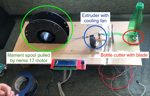
Before we started, we decided to check what we had in stock. We found some useful things from a 3D printer project at SFL: - Nema 17 motor - Power supply - Filament extruder - DC fan - LCD screen
DIVIDING THE WORK
- Zina Choden Yonten- Team Lead, 3D design, Documentation.
- Sonam Paldon Dorji- Programming, Hall Effect sensor team, Documentation.
- Anith Ghalley- Hall Effect Sensor team (mechanism), Programming, Documentation.
- Kencho Wangdi - Extruder modification, Assemble components, Prototyping, Wood works.
FIRST PROTOTYPE
We got inspiration from the Precious Plastics Pet bot machine
Initially, we thought about recreating the machine but it is not open source so we had to start from scratch. Therefore, Fran challenged us to make the first prototype in about 2 hours.
We made a rough prototype to get a general idea about the machine using cardboard, hot glue and tape.
HALL EFFECT SENSOR DESIGN
MECHANISM
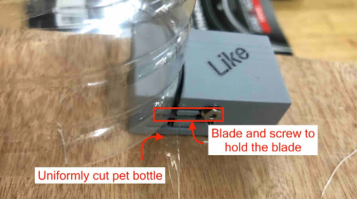
The first step in the machine is cutting the blade. I initially tried to design one with linear bearings:
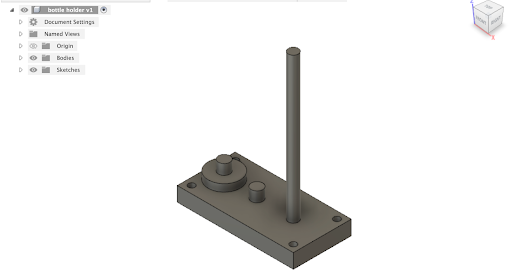
However, I wasn’t sure how to integrate a blade in the design. Sibu suggested that I look at some that were on thingiverse. I 3D printed the part and then placed a blade inside. To keep the blade in place, we drilled two screws on either side of the blade holder.
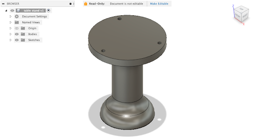
Machine stand design:
EXTRUDER MODIFICATION
For extruding the pet bottle we have used a 3D printer Extruder.
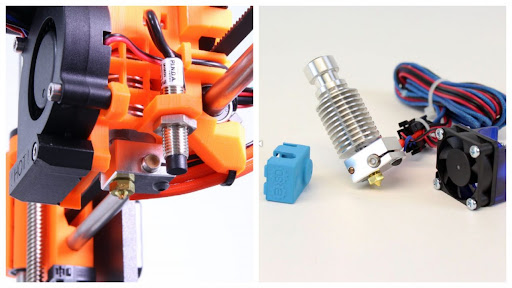
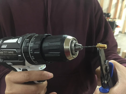
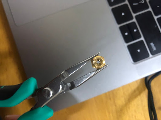
To make it as an extruder for our machine, first we have to modify the nozzle of the extruder. The standard 3D printer nozzle diameter is 0.4mm and it’s my responsibility to change the diameter to 1.7mm. To modify the nozzle diameter I have used a drilling machine with bit size 1.7mm.
Hall effect sensor
I modified the Neil’s hall effect board. For convenience reason, I made some changes in the placement of the components. I placed the hall effect sensor and the ISP 2X3 male header and the FTDI in the 2 extreme ends as I wanted the hall effect sensor to sense the magnetic field from one end while the board is connected to the supply at the other end.
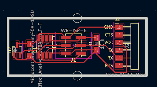
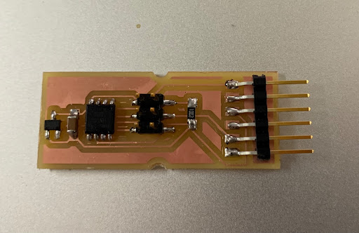
I milled the board in the Roland SRM20 and soldered the components
To test the hall effect board:
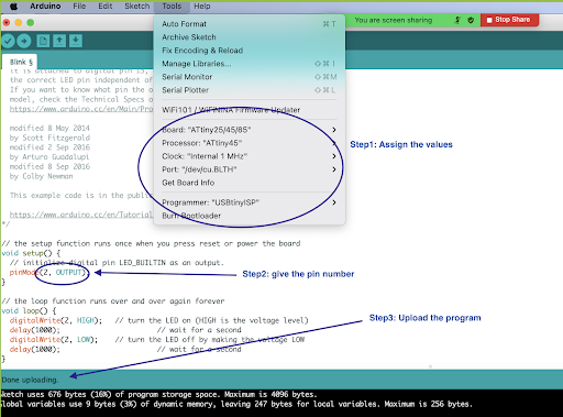
Since the hall effect board does not have any LEDs. To test whether the board is working or not, I uploaded the blink program to the ISP board and the LED blinked.
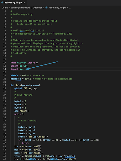
To open the hello.mag.py
-
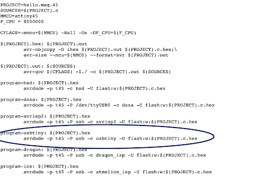
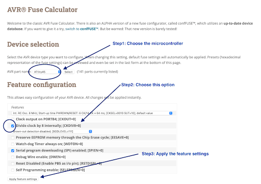
The internal frequency of the ATtiny45 is 1MHz but the Neil’s program is for 8MHz. To change the setting, calculate the fuse (to manipulate the attiny45 to our requirement)
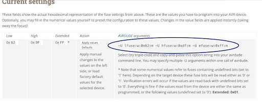
We have the run in the terminal the program circled below, after making some changes to the fuse setting:
To calculate the fuse settings:
Copy the circled fuse setting:
-
Download the hello.mag.45.py from here . Make changes to the hello.mag.45.py file and keep the file in your desktop.
- In the terminal:
cd desktop
avrdude -p t45 -P usb -c usbtiny -U lfuse:w:0xe2:m -U hfuse:w:0xdf:m -U efuse:w:0xff:m
ls /dev/tty*
python3 hello.mag.45.py /dev/tty.usbserial-A50285BI
Arduino Mega and Ramps
We are using Arduino Mega to program our machine and using ramps to control the motors.
Connections:
- Power supply(12 V)- input of 230V is given to the power supply and output is 12V
- From the power supply, 12V is given to the arduino Mega
- Motor- connected to the E0 with a motor driver
-
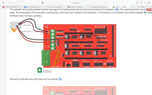
Extruder connected to D10 for power supply and connected to T0 for temperature sensing.
-
Fan connected to 12V aux
- **LCD is connected to AUX-4 pins
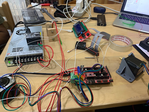
What wiring connections really looks like:
To control the motor :
- I downloaded the marlin firmware
- Then, I tried the repetier software to control the motor but it did not work. Next, I downloaded the Cncjs software
- Since I am using a stepper motor, I connected the motor to E0 of the ramps and to run the motor using the ramp, we connected a motor drive on the ramps.
-
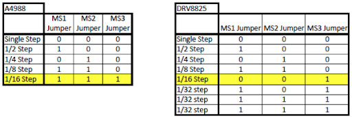
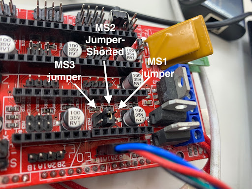
To increase the resolution of the motor (initially 200 steps), I shorted the MS1 and MS2 jumper, now it has 1600 steps.
-
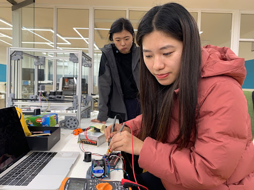
Setting the limit current for the RAMPS motor driver to 0.47V,
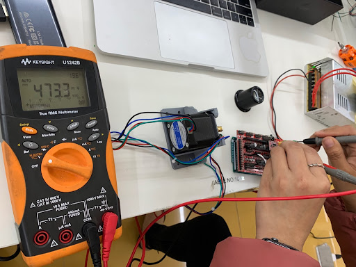
-
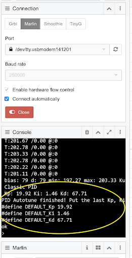
The temperature was not setting to an accurate value in the extruder, so I auto-tuned the PID
To auto-tune the PID, run the command in the CNCjs software.
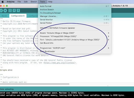
Uploading the Marlin program in the ArduinoMega
-
Since the stepper motor is connected to E0, set the value
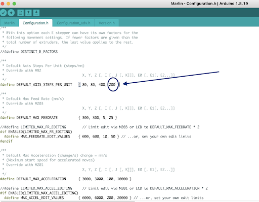
-
Set the values of PID after auto-tuning:
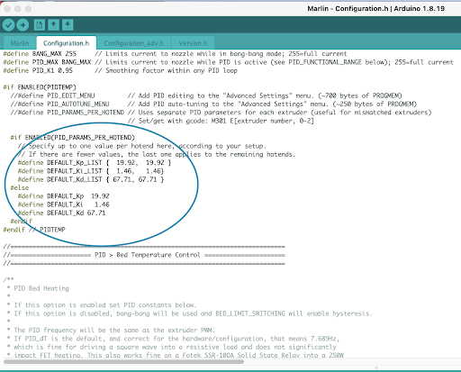
-
Assign the microcontroller values and then upload the program:
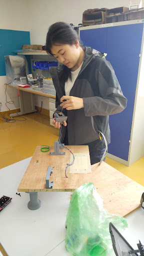
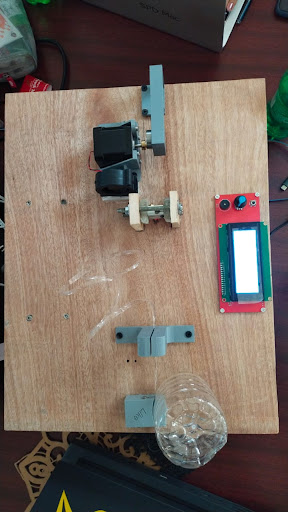
ASSEMBLY
Once all the machine parts were ready, Zina and I assembled all the parts into 18mm cardboard. We wanted to place the controller and power supply at the bottom of the board
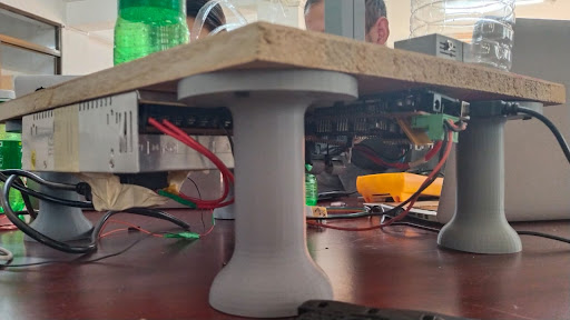
The extruder machine parts on top of the table. To make the connection clean, we drilled holes for every wire connection below each machine part.
Amplifying Mechanism.
With our approach to convert the pet bottle to 3D filament has the high possibility of creating an uneven diameter of the filament. Therefore it is necessary to control the extrusion of the filament as per the diameter of the filament from the extruder.
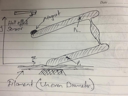
Our mechanism must be able to detect the variation of about 0.5 mm in the diameter of the filament. Therefore our Aim is to create an amplifying mechanism which would have an amplification factor of x20. SInce we want to use the Hall effect Sensor to detect the variation.
As per the video in the Input week design of the hall effect sensor. We have observed that a considerable variation of 2 cm is required for the hall effect to detect a measurable variation between the sensor and the magnet.
Therefore, after a quite a long time of brainstorming and exploration we decided to use the concept of first class lever.
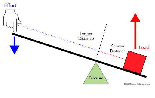
The Ratio between the Load Arm to the effort Arm will give us the scale with which the movement of the effort arm will make a huge variation at the end of the load Arm.
With this concept, we have designed a combination of two first class levers. Where the load arm of the first lever will create a huge variation to the load arm of the second lever.
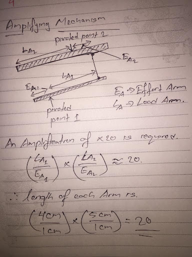
The First iteration of the mechanism was a to basically create the combination of the levers.
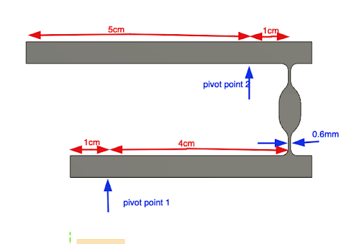
The we understood that the pivoted point would need some joints, which should provide the freedom for rotational movement but should restrict translational movement.
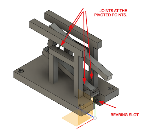
But all these joints broke while removing the support after printing. Therefore we are now looking forward to making more reliable joints in the future iterations of the design. For now we manually created the pivoted points at the support and at the lever to test the amplification of the mechanism.
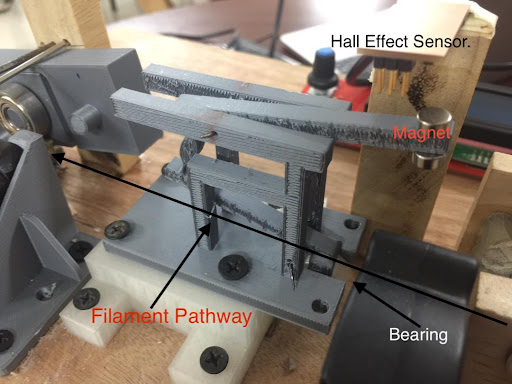
Finally the mechanism was installed on the machine. Then we tried to check variation on the output from the hall effect sensor. When the filament passed through the pathway, the variation on the hall effect output was observed. Therefore, we plan to take this output from the hall effect board and control the speed of the motor.
Result:
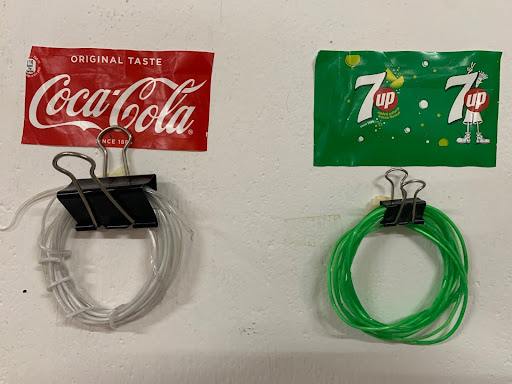
The filaments:
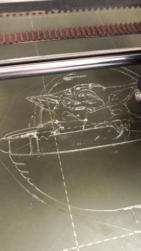
We printed a yoda from mineral water bottle waste:
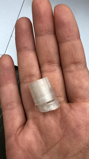
Problems faced:
The filament produced from the coke bottles ontains air bubbles and is too thick, so while 3D printing the extruder could not print at all due to uneven diameter. 2. So next we tried a mineral water bottle (the plastics were thinner). We could print using the filaments produced from the mineral water bottle wate. The filament was flexible.
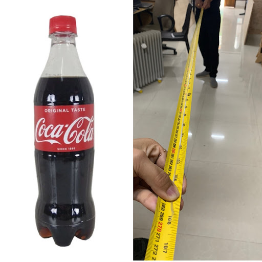
Measurements:
A 600ml bottle can produce 500 cm filament.
Future works
- Design enhancement of the amplifying mechanism so the problems related to uneven diameters are solved.
- Make the machine even more user-friendly while operating.
- Reduce the size of the machine, so it is portable.
- Incorporate spool holder so that filament produced can be automatically stored
- Incorporate the output from the hall effect board to control the speed of the motor
- Design a better hodler for the extruder.
- Improve the overall aesthetic of the machine.
Orginal files.
Download all the original files from here.