Week6- Electronics design
Assignment
group project:
- use the test equipment in your lab to observe the operation of a microcontroller circuit board
individual project:
- redraw an echo hello-world board, add (at least) a button and LED (with current-limiting resistor)
- check the design rules, make it, and test that it can communicate
- extra credit: simulate its operation
Group assignment
Digital oscilloscope
An oscilloscope is used to investigate the health of electronic circuits by analyzing the signals at different points in the circuit. So the most fundamental goal of any oscilloscope is to show you the signals in your circuit.
Machine: Digital Oscilloscope- GDS-1202B
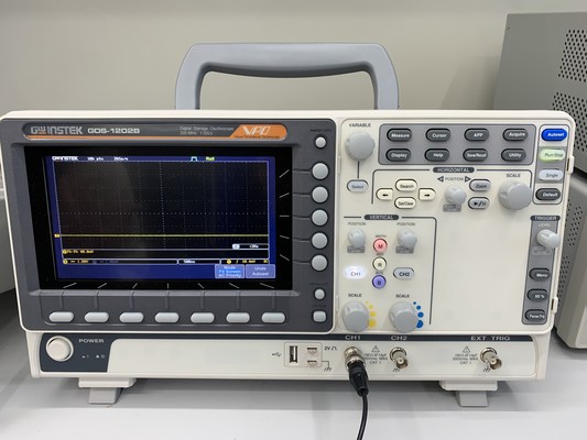
Features of oscilloscope
- Channels
- There are two channels, CH1 and CH2 in the GDS-1202B digital Oscilloscope so we can compare 2 signals at a time.
- Press on CH1 (it will glow to indicate) to show the signal from the probe connected to channel 1 and press on CH2 to show the signal from the probe connected to channel 2 and press on both CH1 and CH2 to compare 2 signals connected from CH1 and CH2.
- Horizontal and vertical settings
- We can change the horizontal and the vertical settings to get proper reading of a signal
- Horizontal position- Moves the waveform left and right.
- Vertical position- Moves the waveform up and down.
- Scale settings
- Vertical scale- sets the value of vertical divisions of the graticule in volts/div. Turning this control clockwise makes the waveform appear larger on the display, and vice versa.
- Horizontal scale- Sets the time scale (seconds/division) and automatically adjusts sampling rate for all waveforms. This makes the waveform appear wider or narrower on the display
- Autoset
- Autoset button is used to fit the signal on the scope display.
- Run/Stop
- We can click on run/stop button to stop the moving signal so we can study the signal better.
- Test channel
-
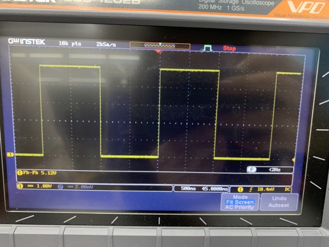
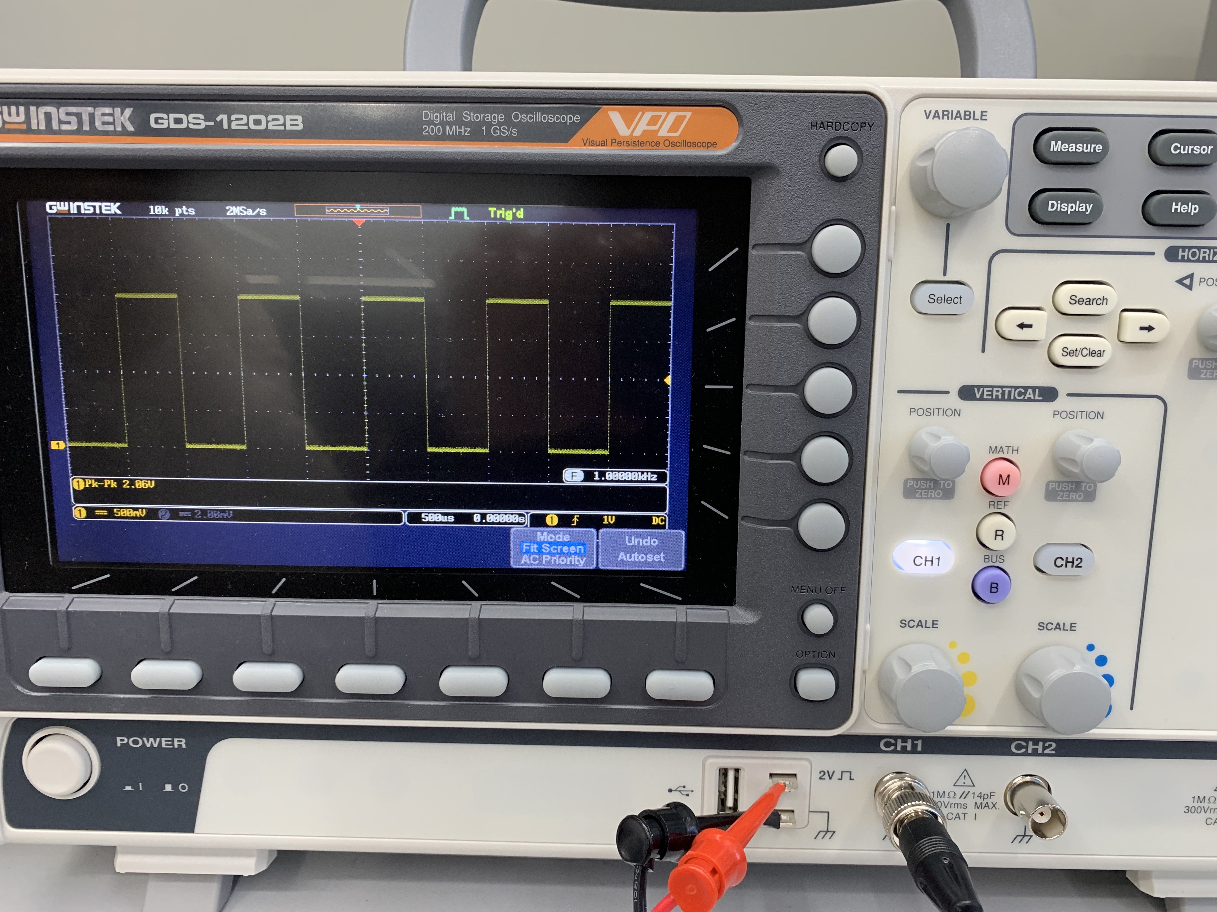
We can test if the oscilloscope is functioning or not by connecting the probes to the 2V square wave and checking the signal on the display
-
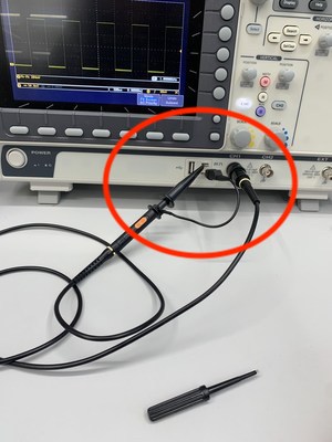
Connect the ground lead of the probe to the ground of the oscilloscope and the tip of the probe to the 2V square wave of the oscilloscope.
-
The display will show a square wave
-
The x-axis represent the volatge.
1 unit of x-axis= 500mV
-
The y-axis represent the time.
1 unit of y-axis= 500 micro sec
-
The signal signifies that
Voltage= 500mV* 4units= 2V
Time= 500 micro secs* 2= 1000 micro secs
- Calibration
- Calibration is the process of configuring an instrument to provide a result for a sample within an acceptable range. So ensure to calibrate your oscilloscope from time to time.
- We can calibrate the oscilloscope using a screw that is provided along with the oscilloscope.
Testing microcontroller on oscilloscope
-
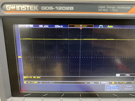
To test the power signal in the board, I placed the red(positive) probe to the VCC pin in the male connector and the black (negative) probe to the GND in the Male connector
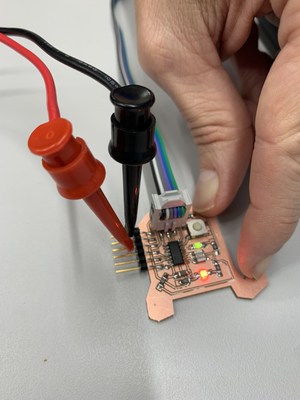
X-axis shows the voltage and the y-axis shows the time
- x-axis 1unit= 2V
- y-axis 1unit= 5 ns
-
To test the signal that the green LED is receiving from the ATTINY 44 microcontroller, I placed the red(positive) probe to the positive of the Green LED. and the black (negative) probe to the GND.
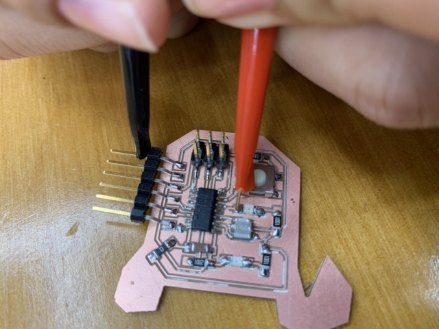
Since the board to programed to blink, the volatge changes from 0V to 5V and then back to 0V with delay of 1000 ms
X-axis shows the voltage and the y-axis shows the time
- x-axis 1unit= 1V
- y-axis 1unit= 500ms