14. Networking and communications
For this week’s assignment, we looked at Networking and Communication .This week looked at the following:
Group assignment:
-
Send a message between two projects.
-
Document your work to the group work page and reflect on your individual page what you learned.
-
Group Project Link
Individual assignment:
- Design, build, and connect wired or wireless node(s) with network or bus addresses
Group Assignment Reflection
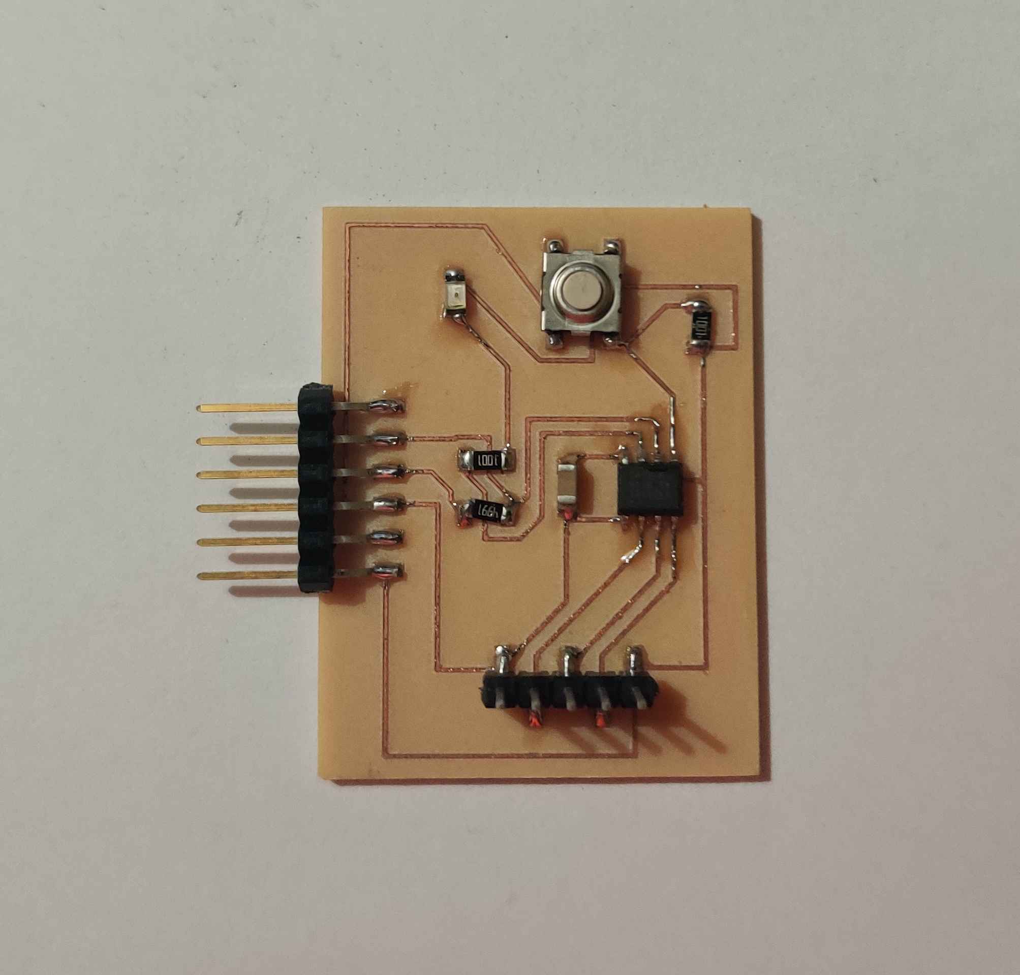
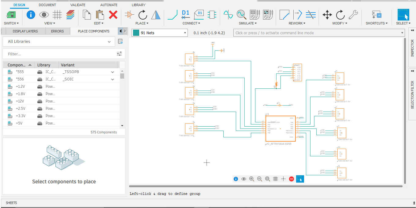
For this weeks assigment we looked at communicating between two microcontoller boards I created. I reviewed two of my fellow Fab Academy students Nervene Bhagwandass & Marvin Holloway to learn from thereexperiences. I also reviewed the student who they both drew inspiration from for this project Adreian Torres.However, as Fab Academy is fast paced and efficient use of time is critical, I decided to use two boards I had previously created. The two microcontrollers used for this assignment were the ATtiny 412 and ATtiny 1614.
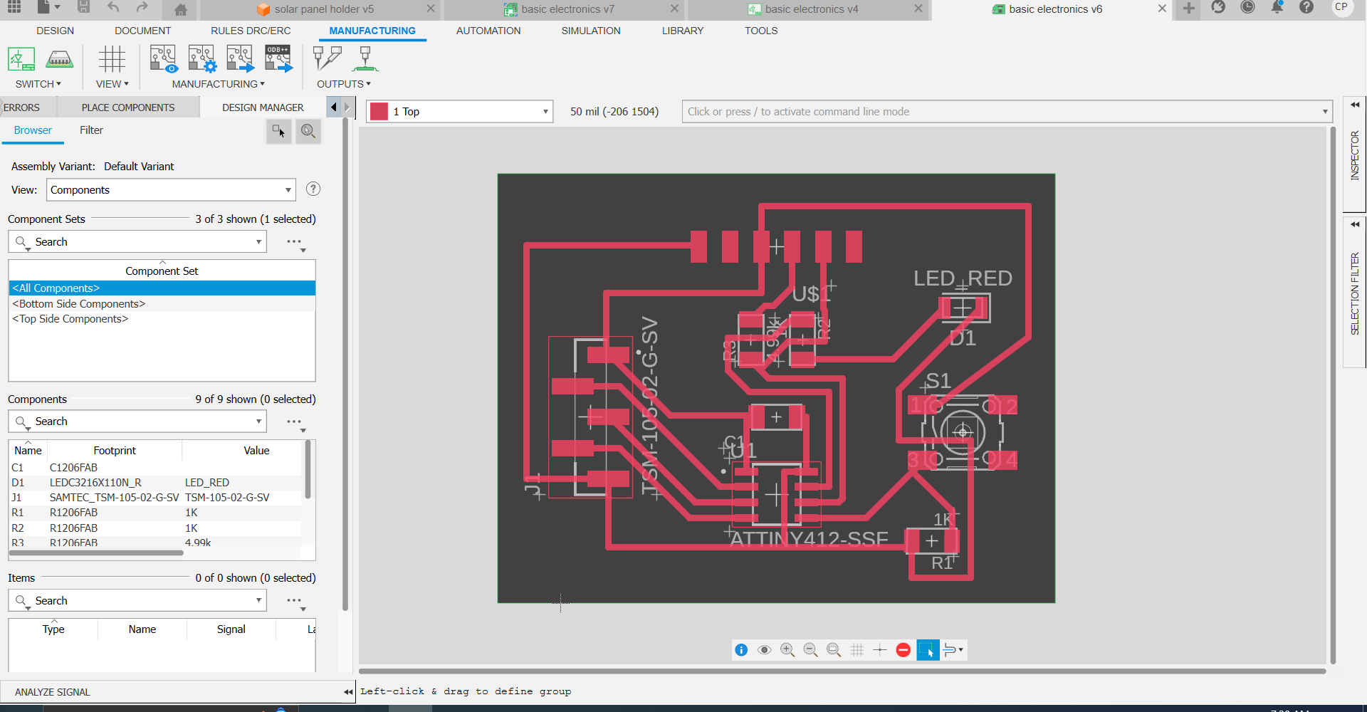
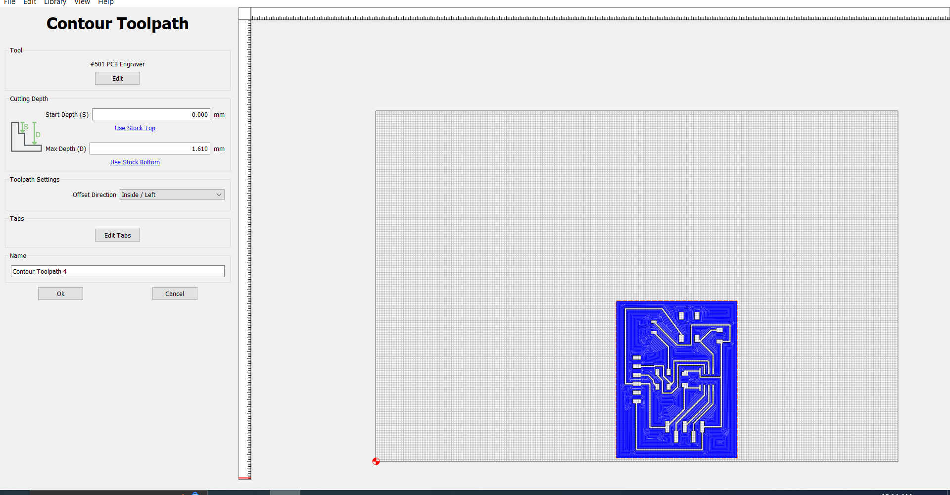
1.The first thing I did was take out the boards I created during the Electronics Production & Output Devices week.
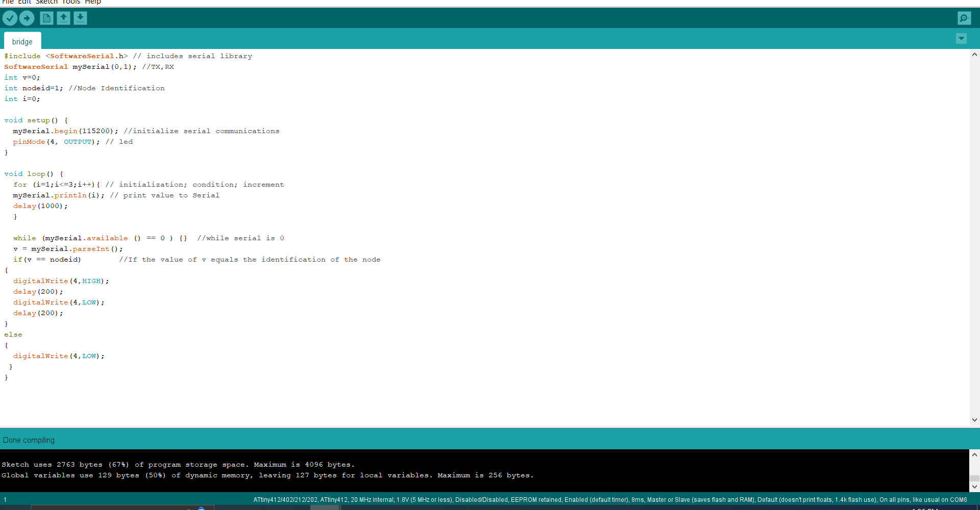
2.Then I reviewed the code used by the other students for the bridge and added some additional comments to understand the code fully
#include <SoftwareSerial.h> // includes serial library
SoftwareSerial mySerial(0,1); //TX,RX
int v=0;
int nodeid=1; //Node Identification
int i=0;

void setup() {
  mySerial.begin(115200); //initialize serial communications
  pinMode(4, OUTPUT); // led
}

void loop() {
  for (i=1;i<=3;i++){ // initialization; condition; increment
  mySerial.println(i); // print value to Serial
  delay(1000);
  }

  while (mySerial.available () == 0 ) {}  //while serial is 0
  v = mySerial.parseInt();
  if(v == nodeid)        //If the value of v equals the identification of the node
{
  digitalWrite(4,HIGH);
  delay(200);
  digitalWrite(4,LOW);
  delay(200);
}
else
{
  digitalWrite(4,LOW);
 }
}
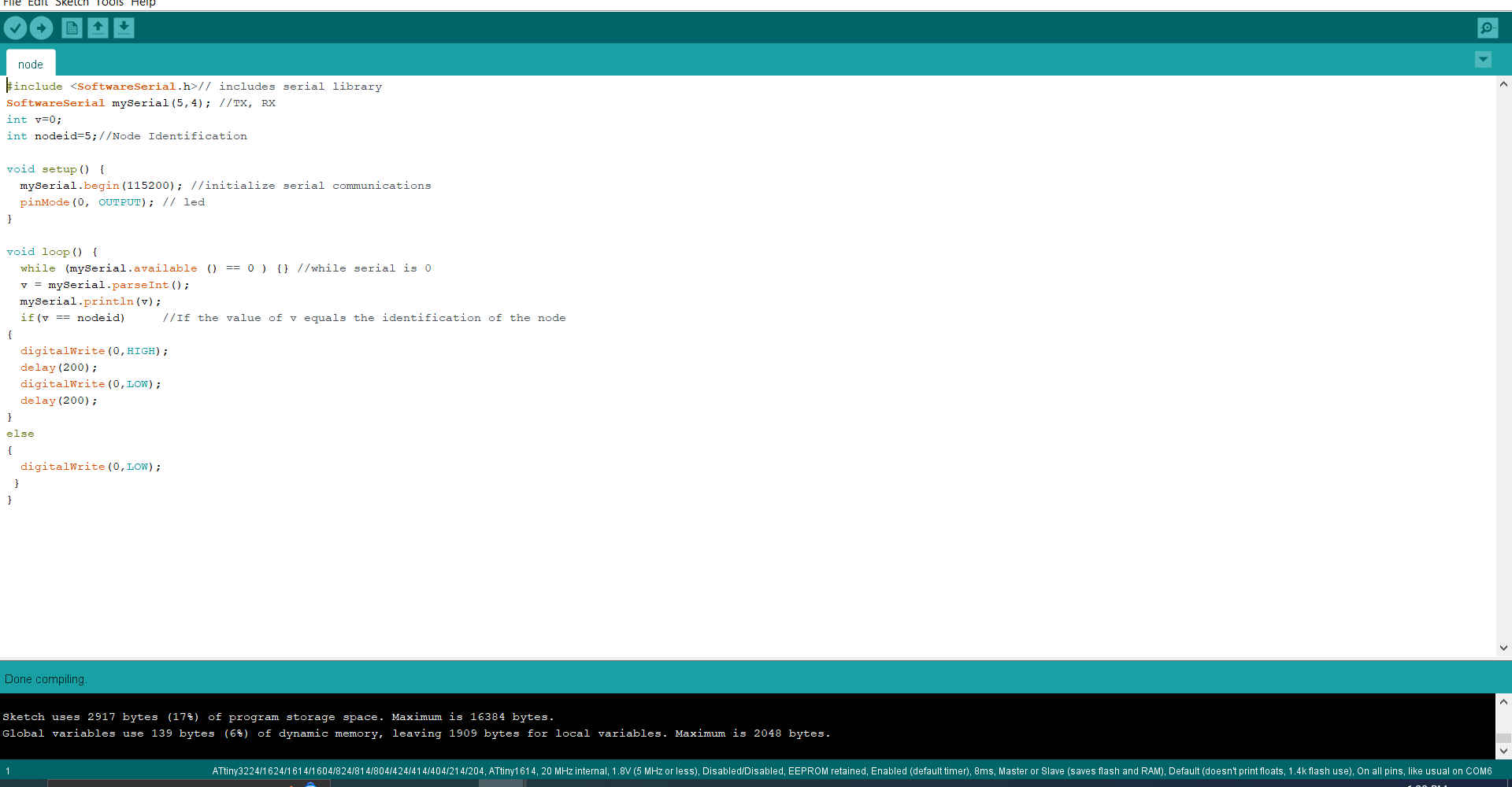
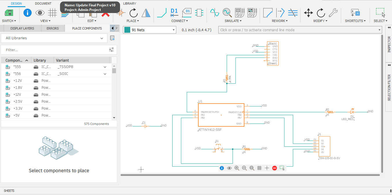
3.Then I reviewed the code used for the node and made changes to the digital pins as I was using the ATtiny 1614.
#include <SoftwareSerial.h>// includes serial library
SoftwareSerial mySerial(5,4); //TX, RX
int v=0;
int nodeid=5;//Node Identification

void setup() {
  mySerial.begin(115200); //initialize serial communications
  pinMode(0, OUTPUT); // led
}

void loop() {
  while (mySerial.available () == 0 ) {} //while serial is 0
  v = mySerial.parseInt();
  mySerial.println(v);
  if(v == nodeid)     //If the value of v equals the identification of the node
{
  digitalWrite(0,HIGH);
  delay(200);
  digitalWrite(0,LOW);
  delay(200);
}
else
{
  digitalWrite(0,LOW);
 }
}
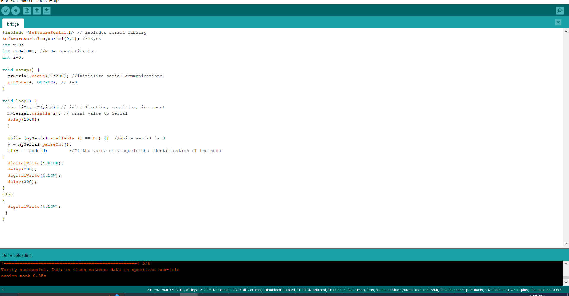
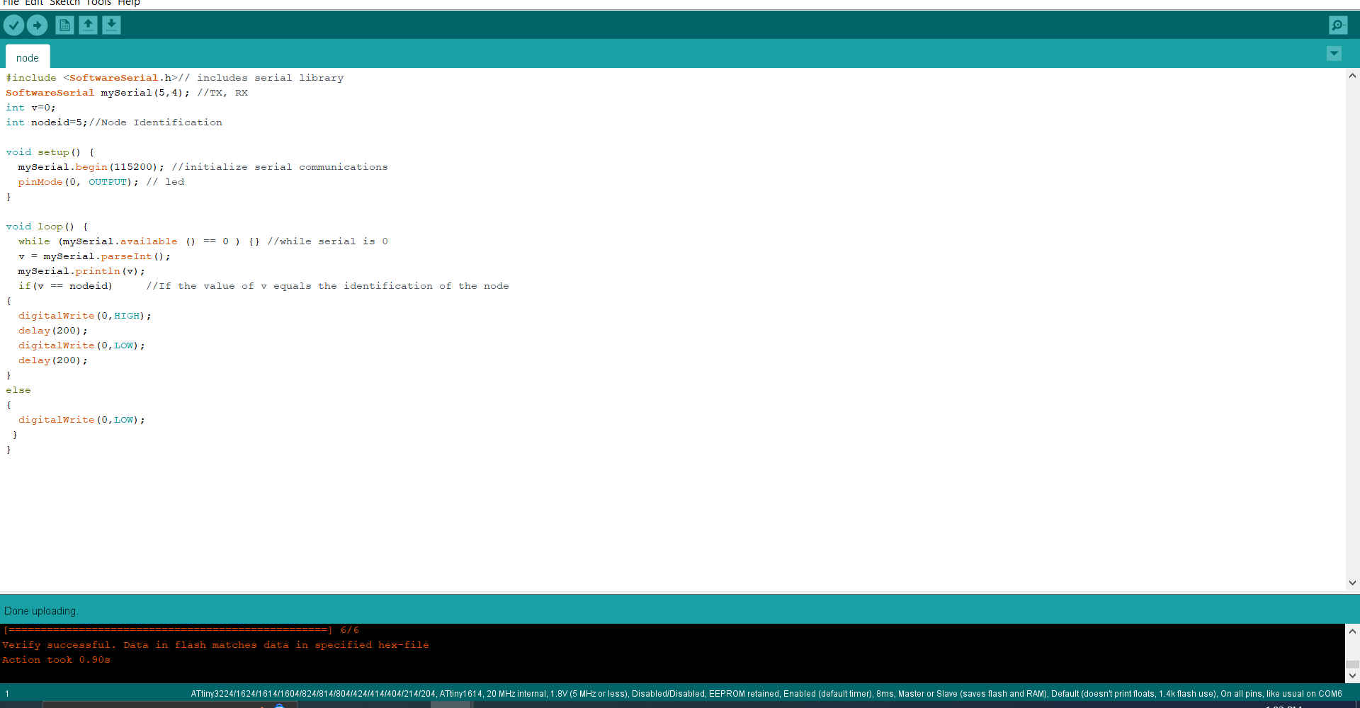
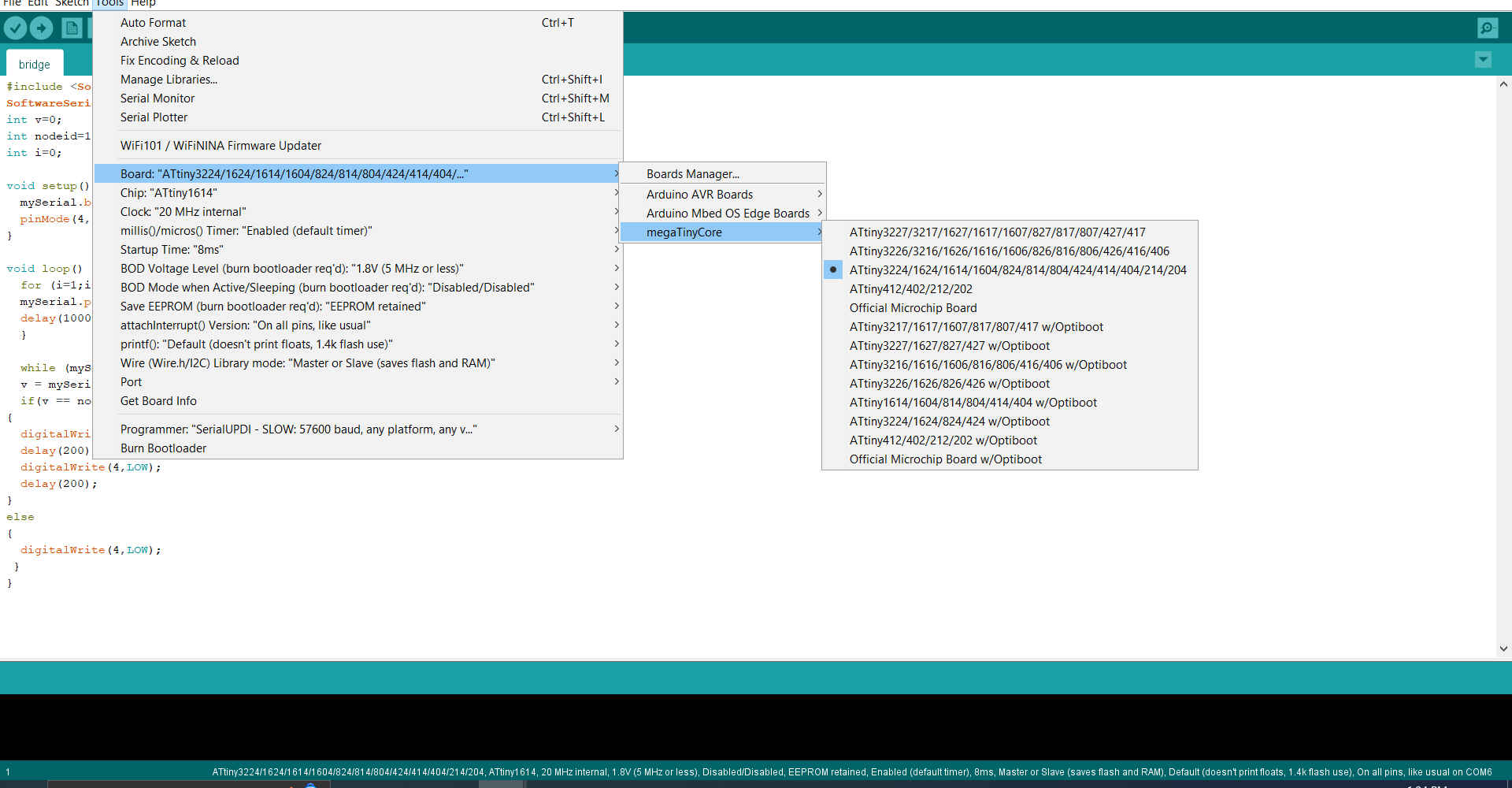
4.Then I verified each code to ensure that they had no errors and uploaded them to each micro-controller. I also ensured that I changes the board manager as both micro controllers were different.