9. Embedded programming
For this week’s assignment, we looked at Embedded Programming.This week looked at the following:
Group assignment:
- Compare the performance and development workflows for other architectures.
- Document your work to the group work page and reflect on your individual page what you learned
Individual assignment:
- Browse through the datasheet for your microcontroller.
- Program a microcontroller development board to interact and communicate.
Group Assignment Reflection
This group assignment has shown that microcontrolllers come in different form factors. These do not necessarily determine performance as the old saying goes “Don’t judge a book by its cover”. This also applies to the mircocontroller as it’s look does not determine its capabiltity . Newer micro controlleers are also coming in smaller packages with more memory and faster procesing speeds.It has also highlighted the importance of mnufactured boards as it relates to mass production and product testing.
Micro-controller ATtiny 412
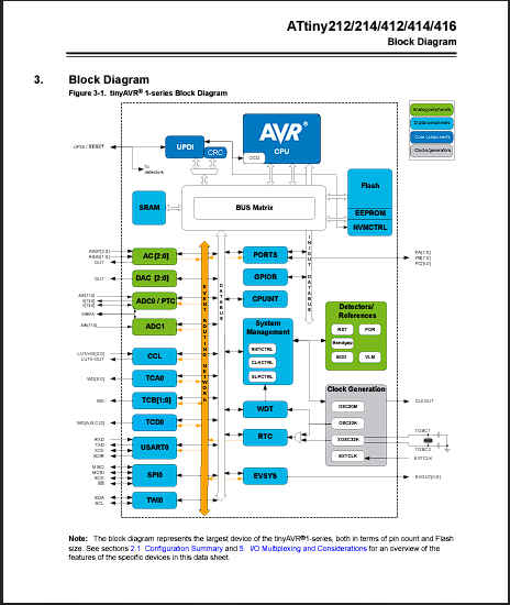
For this assignment I am using the the board I created during my Electronics Production week. This board utilizes the ATtiny 412 micro-controller and as a result I had to review it’s datasheet.The datasheet for a micro controller is an improtant resource because it provides key information about its features and operation.Some usefule information would relate to memory,power usage, peripherals, architechture
Installation of megaTinyCore library.
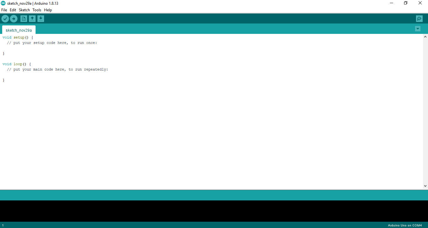
1.After downloading and installing the arduino ide. The application was opened.
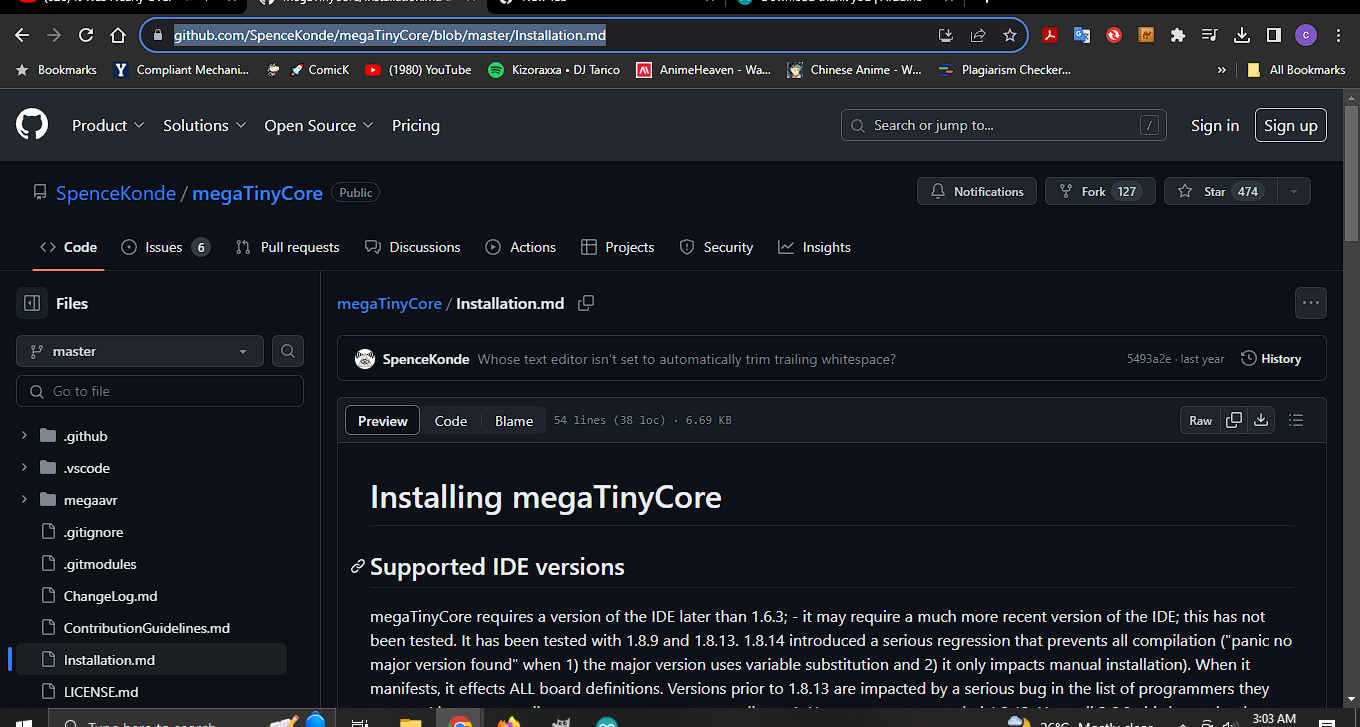
2.Then,I searched for the megaTinyCore library online. I was eventually reached a github page which outlines the process for installing the library.
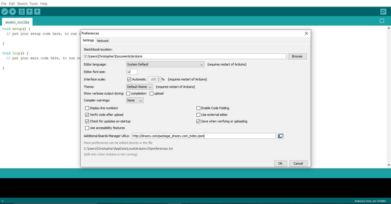
3.Then following the instructions I navigated to preferences to add the url indicated the github documentation.
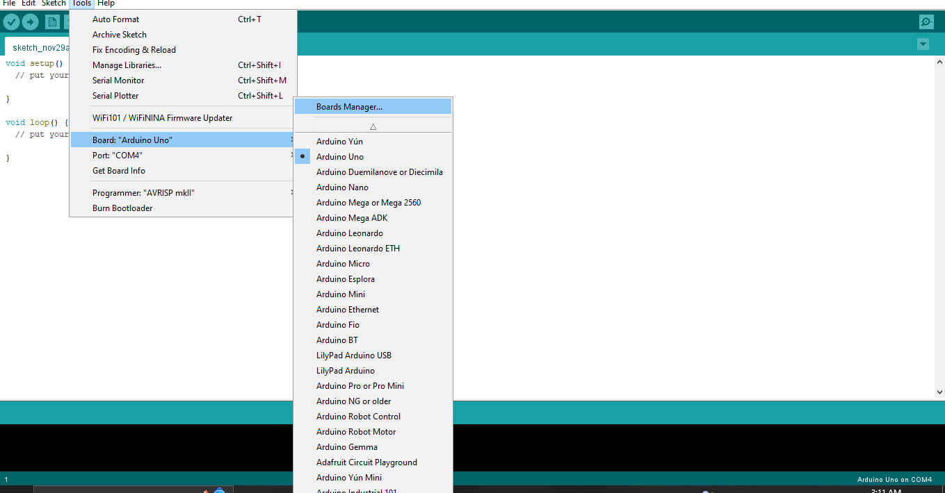
4.Then I navigated to the board manager to install the desired manager.
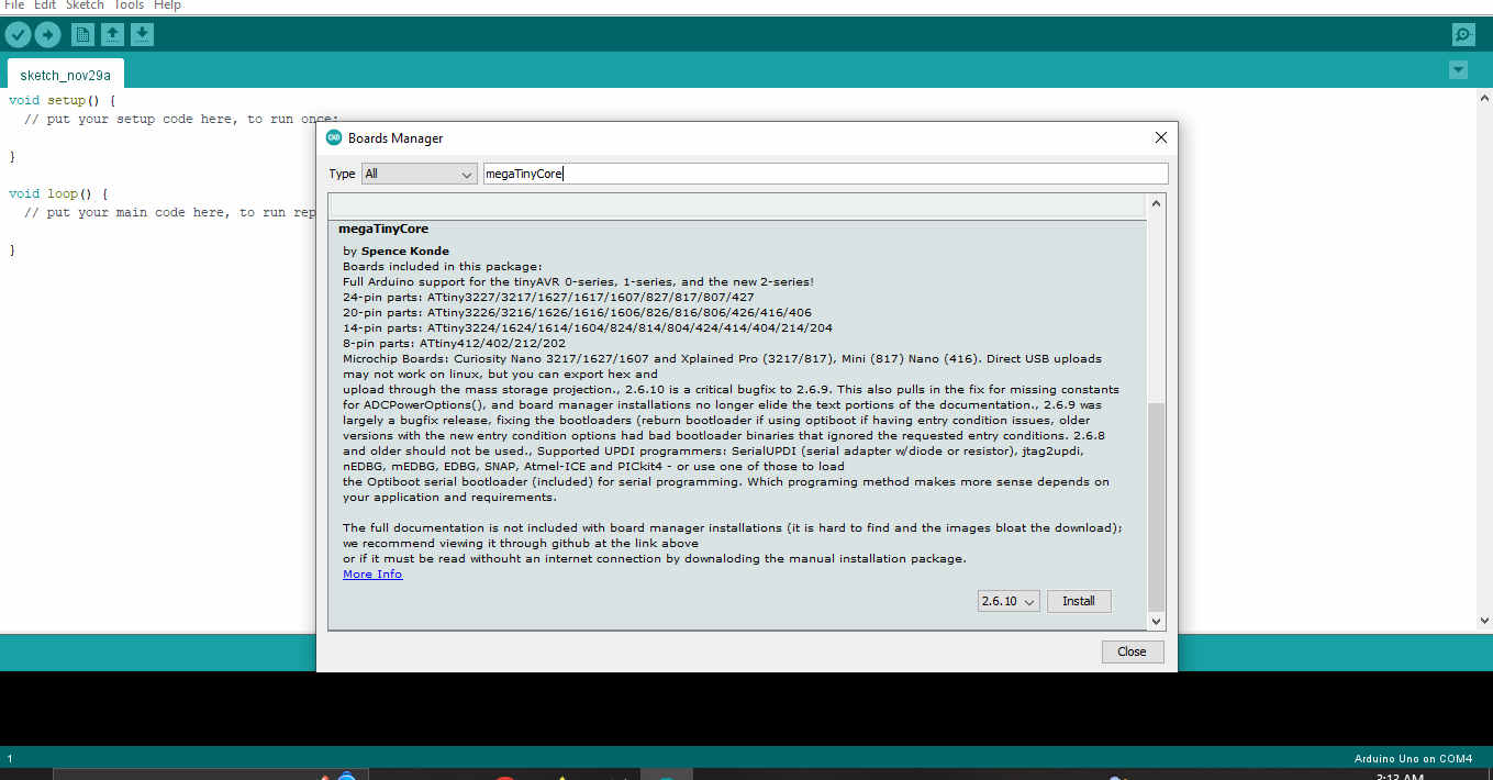
5.Then I confirmed that the manager was installed correctly.
Programming
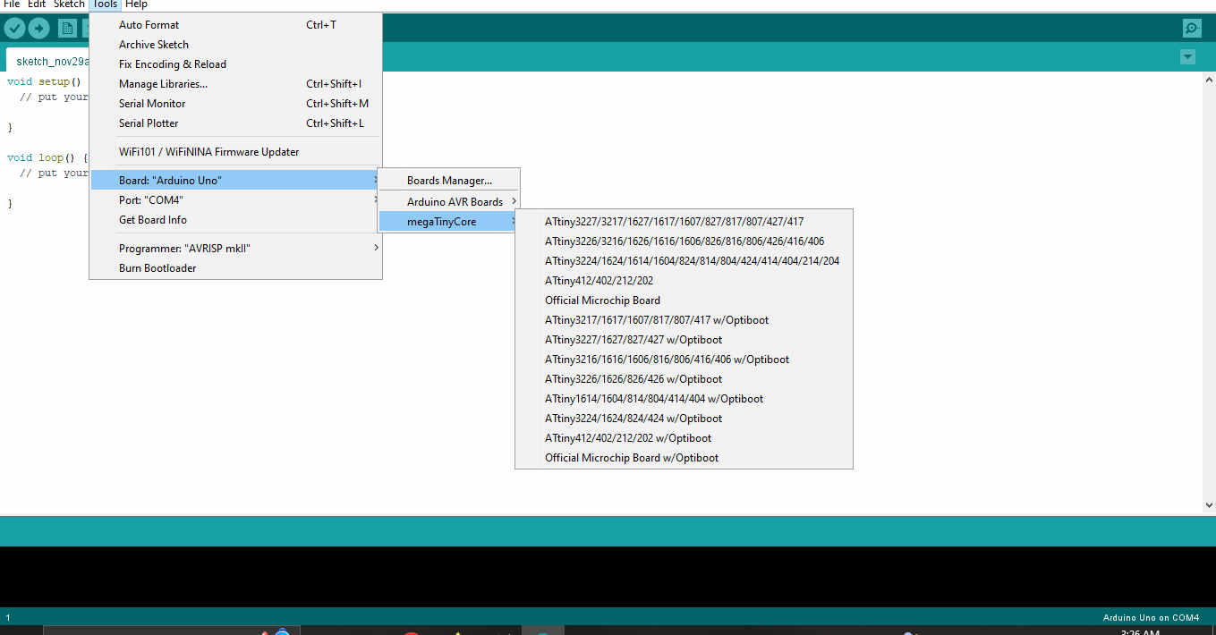
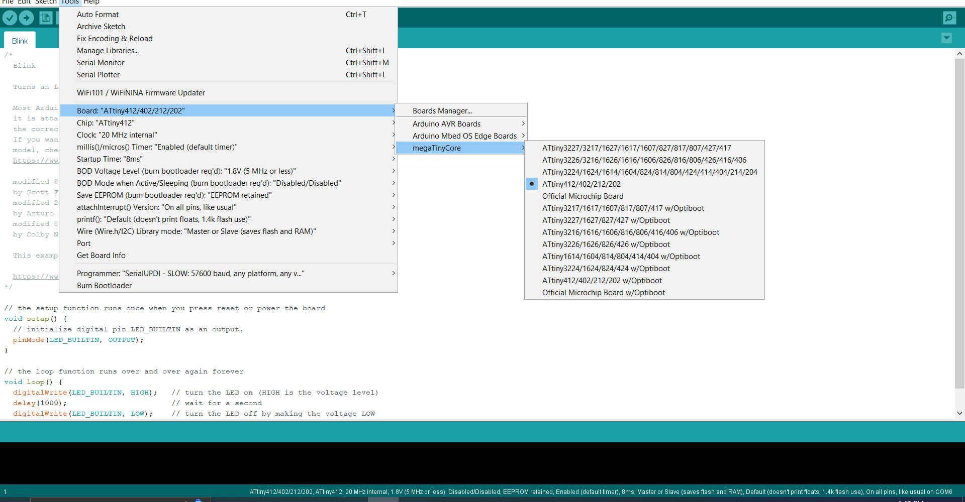
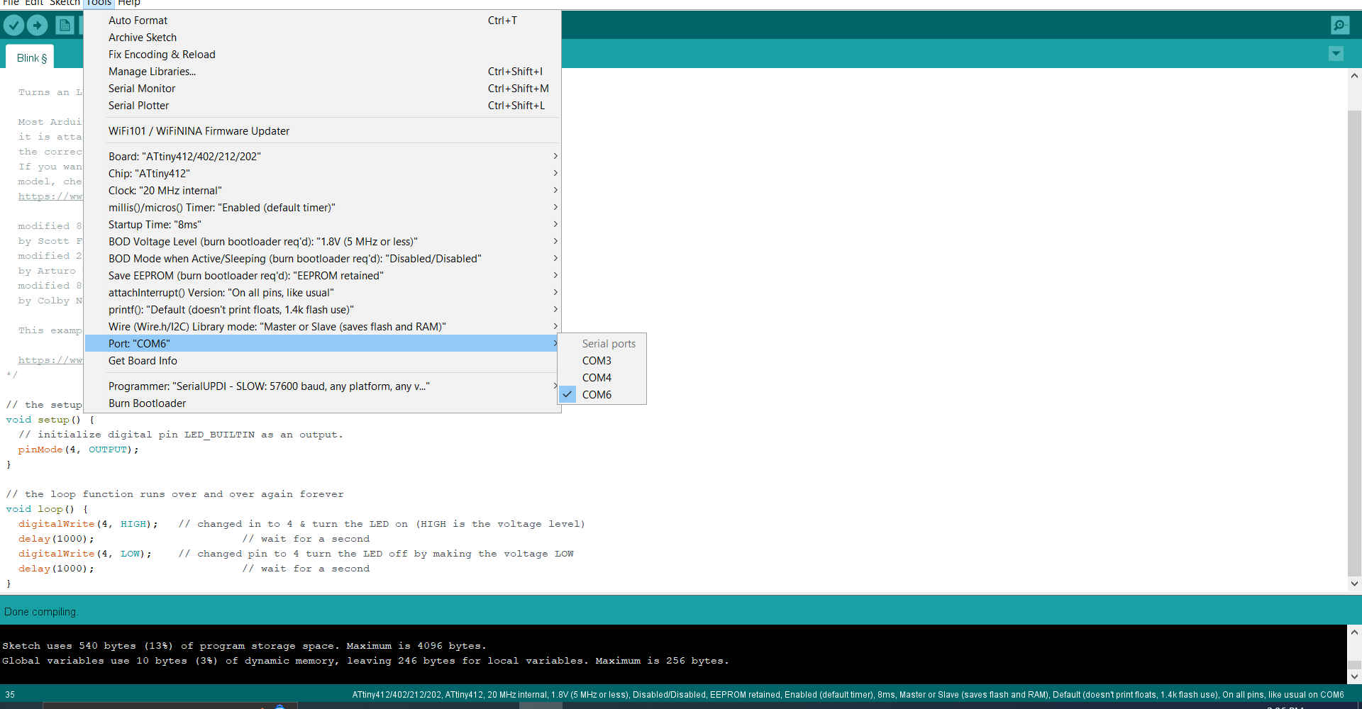
1.The first thing I did was open the Arduino IDE (software used to program the board)and ensured the correct microcontorller was selected.
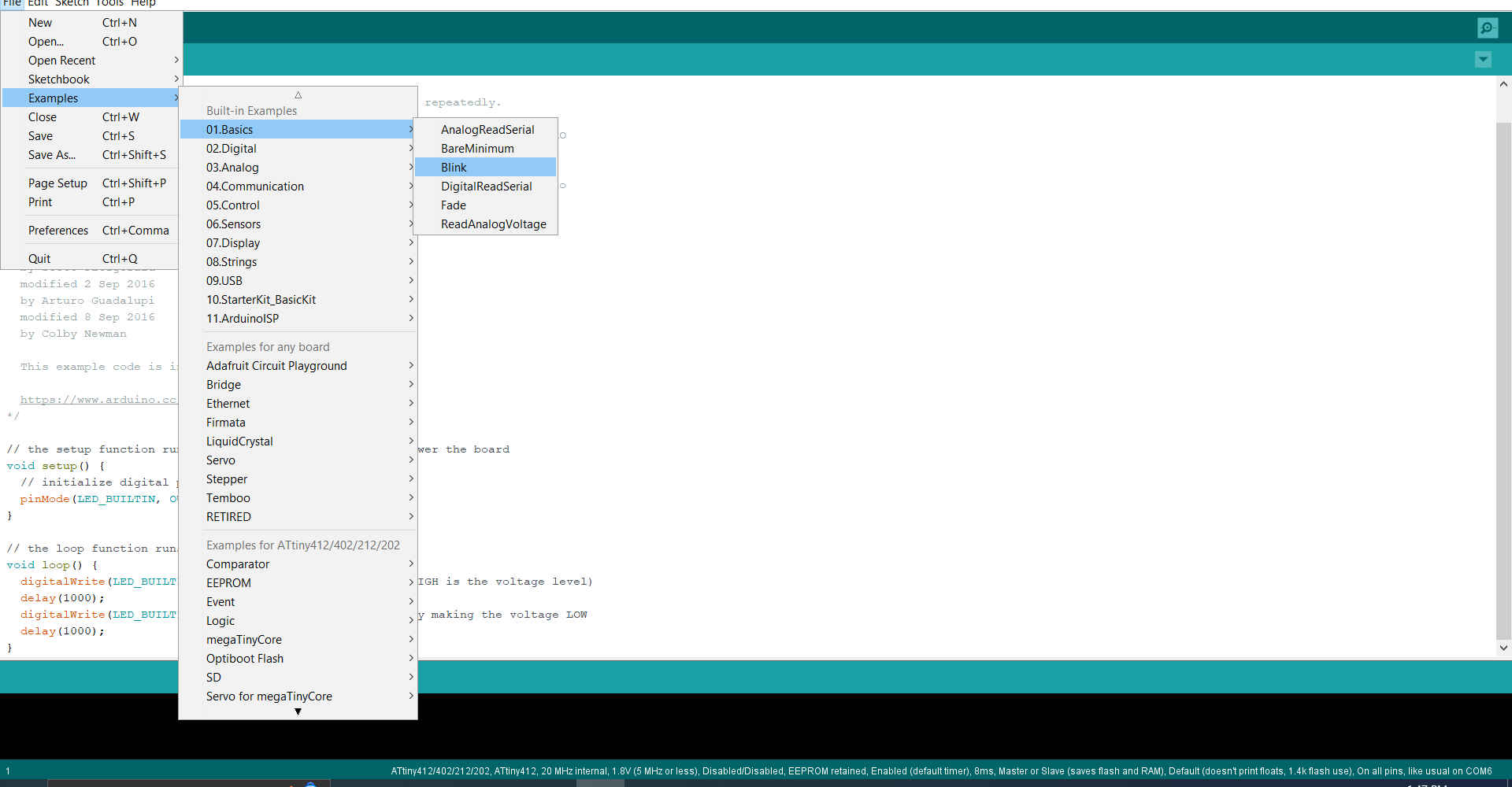
2.Then I opened an example code (basics blink) from the Arduino IDE to test my board.
3.Then I modified the code to ensure it matched where I had my LED.
/*
  Blink

  Turns an LED on for one second, then off for one second, repeatedly.

  Most Arduinos have an on-board LED you can control. On the UNO, MEGA and ZERO
  it is attached to digital pin 13, on MKR1000 on pin 6. LED_BUILTIN is set to
  the correct LED pin independent of which board is used.
  If you want to know what pin the on-board LED is connected to on your Arduino
  model, check the Technical Specs of your board at:
  https://www.arduino.cc/en/Main/Products

  modified 8 May 2014
  by Scott Fitzgerald
  modified 2 Sep 2016
  by Arturo Guadalupi
  modified 8 Sep 2016
  by Colby Newman

  This example code is in the public domain.

  http://www.arduino.cc/en/Tutorial/Blink
*/

// the setup function runs once when you press reset or power the board
void setup() {
  // initialize digital pin LED_BUILTIN as an output.
  pinMode(4, OUTPUT);
}

// the loop function runs over and over again forever
void loop() {
  digitalWrite(4, HIGH);   // turn the LED on (HIGH is the voltage level)
  delay(1000);                       // wait for a second
  digitalWrite(4, LOW);    // turn the LED off by making the voltage LOW
  delay(1000);                       // wait for a second
}
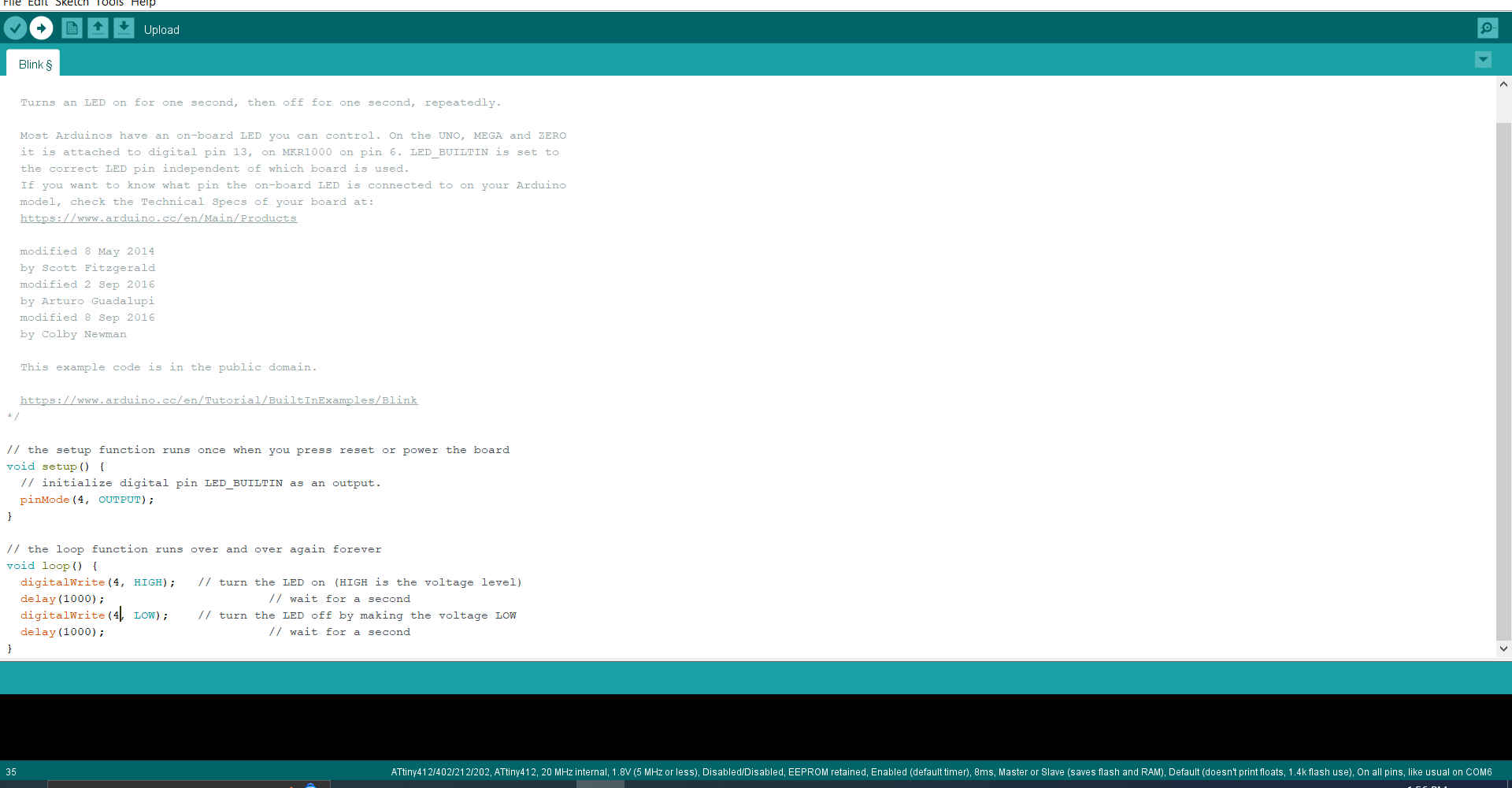
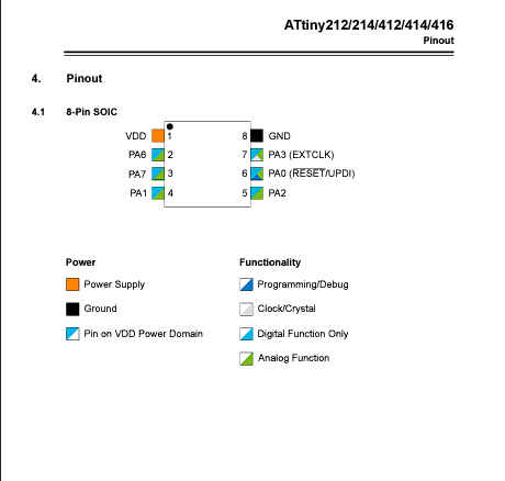
NB. In my case I had to ensure the LED was in the correct digital pin.The pin in the schematic was PA3 which equates to digital pin 4 .
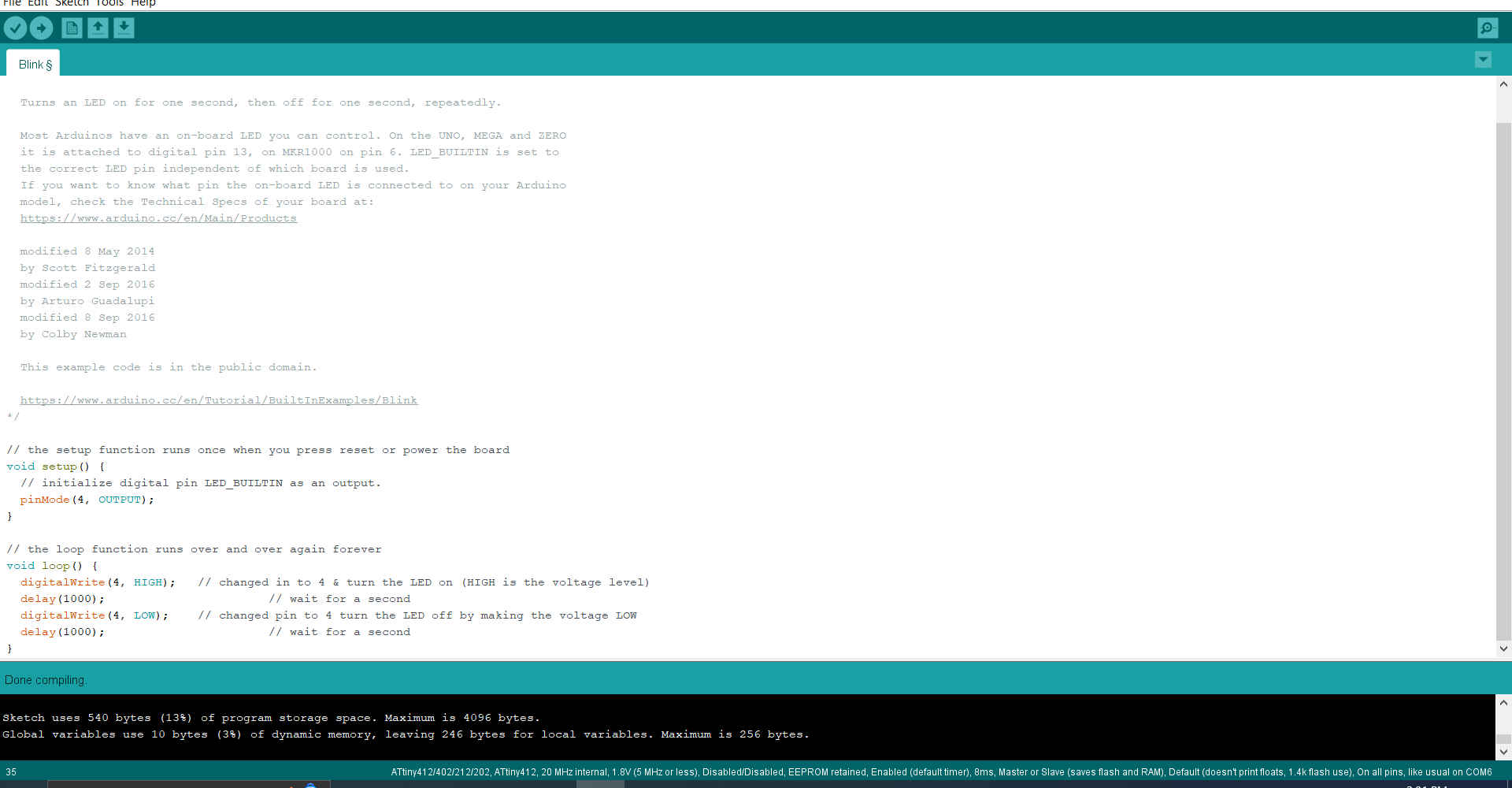
4.Then I verified the code to ensure there were no errors.
5.Then I connected my board to the UPDI cable.

NB. Enure the cable is connected correctly or you will have to make another board.
6.Then I ensured the cable was making connection with my laptop.
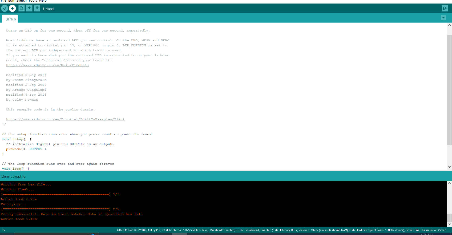
7.Then I uploaded the code to onto my board.
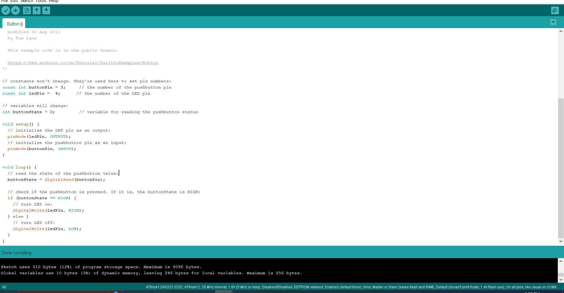
8.Then I looked at incorporating my button to make it more interactive.For this code I used another example code (digital: button) and changed variable to maatch my board.
/*
  Button

  Turns on and off a light emitting diode(LED) connected to digital pin 13,
  when pressing a pushbutton attached to pin 2.

  The circuit:
  - LED attached from pin 13 to ground
  - pushbutton attached to pin 2 from +5V
  - 10K resistor attached to pin 2 from ground

  - Note: on most Arduinos there is already an LED on the board
    attached to pin 13.

  created 2005
  by DojoDave <http://www.0j0.org>
  modified 30 Aug 2011
  by Tom Igoe

  This example code is in the public domain.

  http://www.arduino.cc/en/Tutorial/Button
*/

// constants won't change. They're used here to set pin numbers:
const int buttonPin = 3;     // the number of the pushbutton pin
const int ledPin =  4;      // the number of the LED pin

// variables will change:
int buttonState = 0;         // variable for reading the pushbutton status

void setup() {
  // initialize the LED pin as an output:
  pinMode(ledPin, OUTPUT);
  // initialize the pushbutton pin as an input:
  pinMode(buttonPin, INPUT);
}

void loop() {
  // read the state of the pushbutton value:
  buttonState = digitalRead(buttonPin);

  // check if the pushbutton is pressed. If it is, the buttonState is HIGH:
  if (buttonState == HIGH) {
    // turn LED on:
    digitalWrite(ledPin, HIGH);
  } else {
    // turn LED off:
    digitalWrite(ledPin, LOW);
  }
}
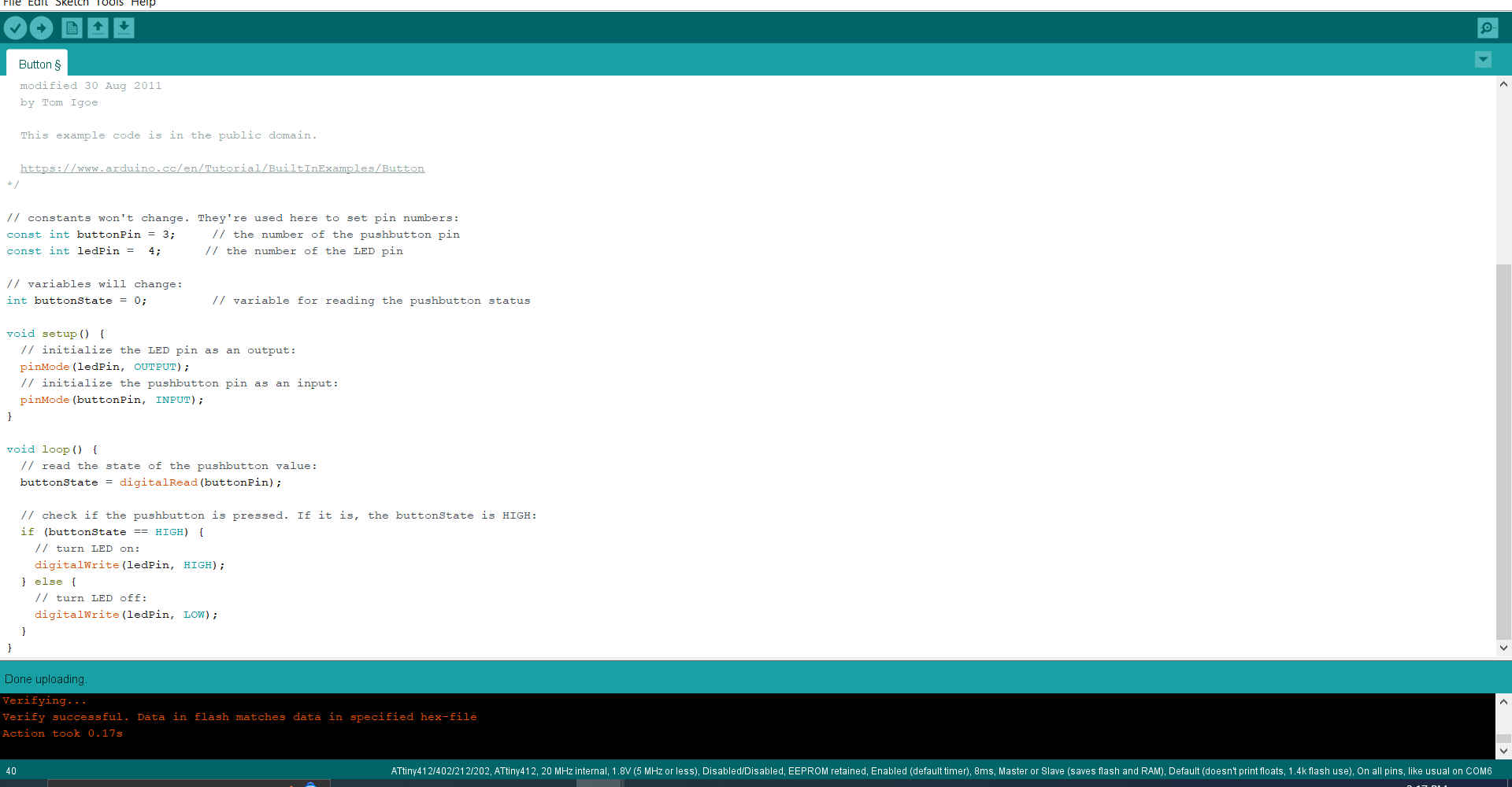
9.Then I verified that there were no errors and uploaded the code to the microcontroller.