Electronics production
Group Assignment
For this week the group members worked on the electronic production group assignment which includes what we learned in electronics and also the PCB fabrication process. It also entails the materials and components used in the production process and how we used the machine to fabricate a PCB. The group also paid attention to certain precautions that need to be taken while using the milling machine.
The objectives of the group assignment are as follows:
-
Characterize the design rules for your in-house PCB production process: document feeds, speeds, plunge rate, depth of cut (traces and outline) and tooling.
-
document your work (in a group or individually)
-
Document your work to the group work page and reflect on your individual page what you learned
Learning Outcomes
-
Describe the process of milling, stuffing, de-bugging and programming
-
Demonstrate correct workflows and identify areas for improvement if required
Group Members
-
Ravi Baldeo
-
Marvin Holloway
-
Terrence Carew
-
Christopher Proute
-
James Khan
-
Nervene Bhagwandass
## What is a PCB?
A printed circuit board(PCB) is basically the backbone of all electronic devices that exist today. It consists of a printed conducting copper circuit on a non-conductive board, components are connected over the traces.
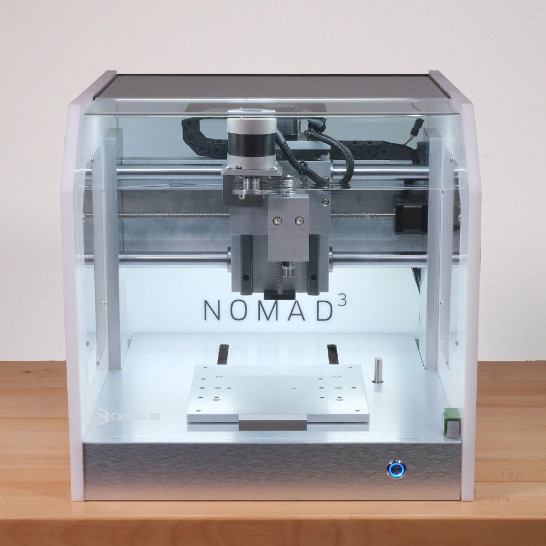
Technical Specifications of the Machine (Nomad 3)
-
Cutting area: 8”(X), 8”(Y), 3”(Z)
-
Outer dimensions: 17.5”(W), 19”(D), 17”(H)
-
Spindle collet: ER-11, 7mm max cutter diameter (collet not included)
-
Spindle RPM: 9000 - 24000 RPM
-
Input voltage: 110V or 220V
Safety Precautions while using the Machine
-
Always wear safety glasses when your Nomad 3 is on
-
Always keep the door closed while the nomad 3 is machining
-
Endmills are sharp and should be handled with care
-
Never reach into the machine while it is running
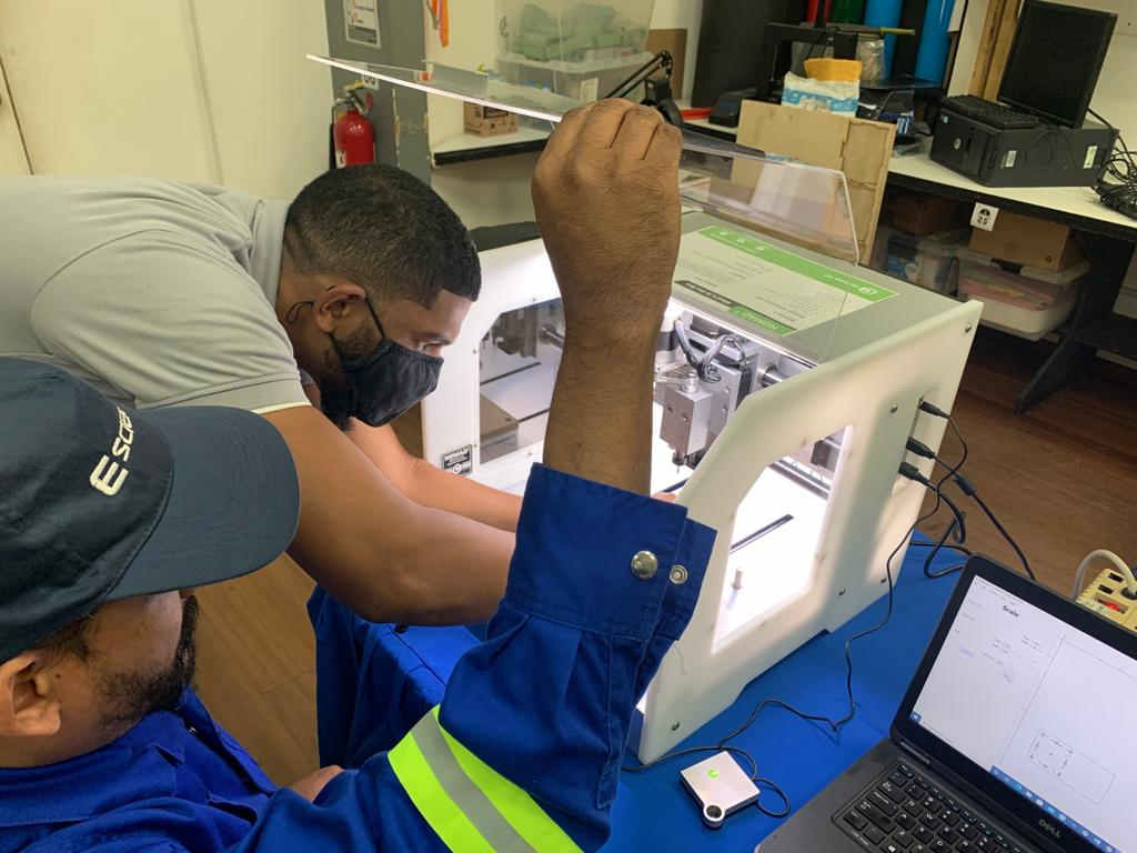
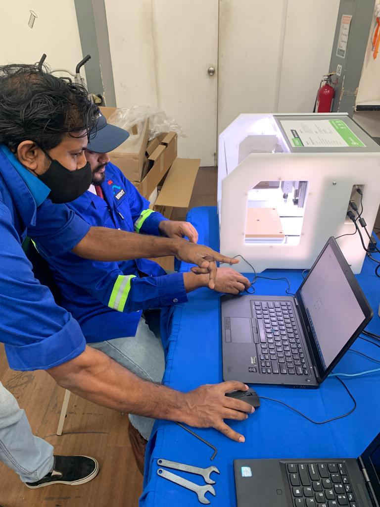
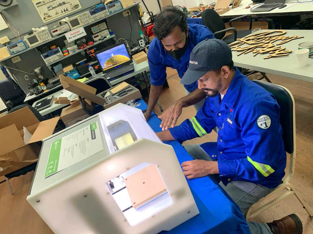
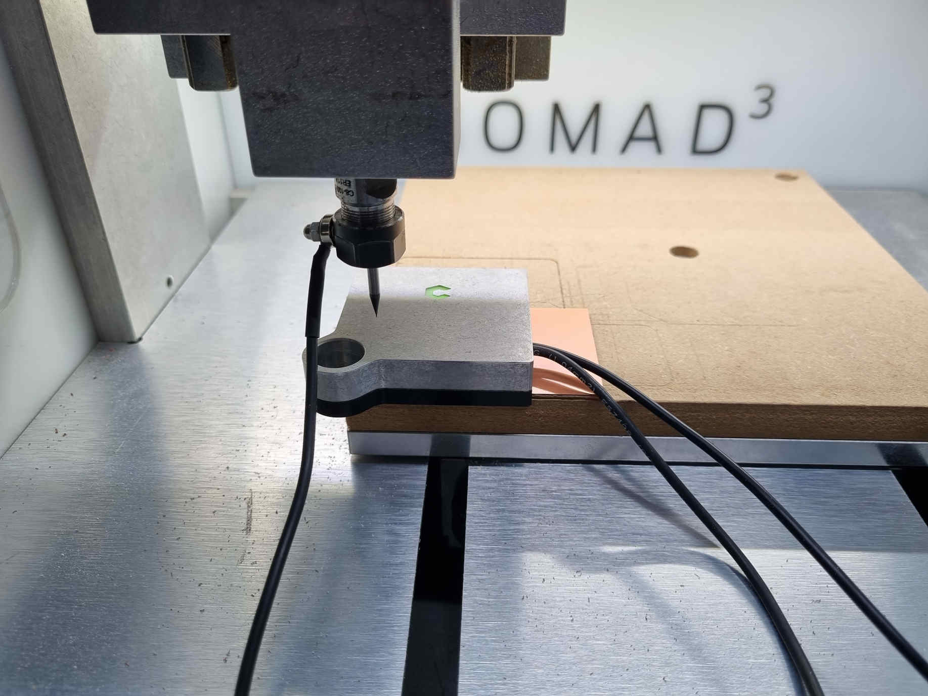
Setting up The Machine
1.The machine that we have to set up at the lab for milling is the Nomad 3 milling machine as shown in the pic below. The machine was unboxed and all the foam padding was removed.
2.The following software was downloaded for setting up of the Nomad3
- Carbide motion is the controlling software for the machine and was downloaded from the following link posted below.
- Carbide create is the Computer aided Manufacturing Software (CAM) that the machine uses to convert the file in order to read it. The software was downloaded from the following link posted below.
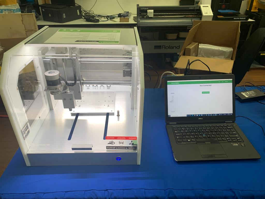
3.Connecting and Homing the Nomad 3.
- Following the required steps from the starter guide the machine was plugged and the required cables installed after which the machine was connected to the nomad3 via the carbide motion software.

4.Installing the wasteboard
- The wasteboard was installed using the 4mm hex key provided.
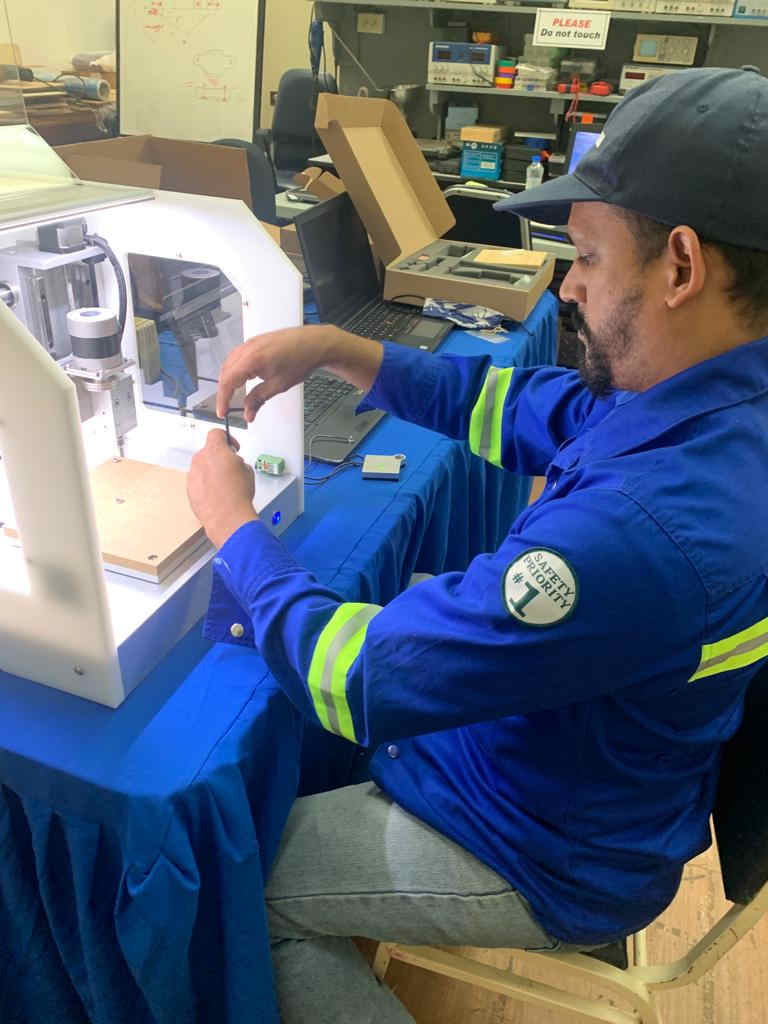
5.Installing the collet, nut and probing pin.
- The collet and nut was installed using the 17mm collet wrench and the 13mm shaft wrench provided.
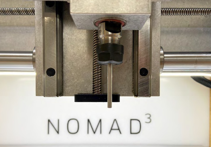
- Probing was also done before the test pieces was cut out.
-
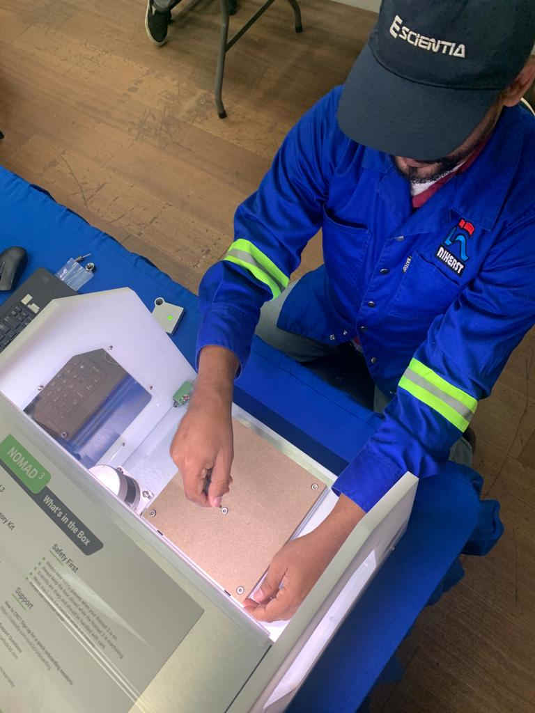
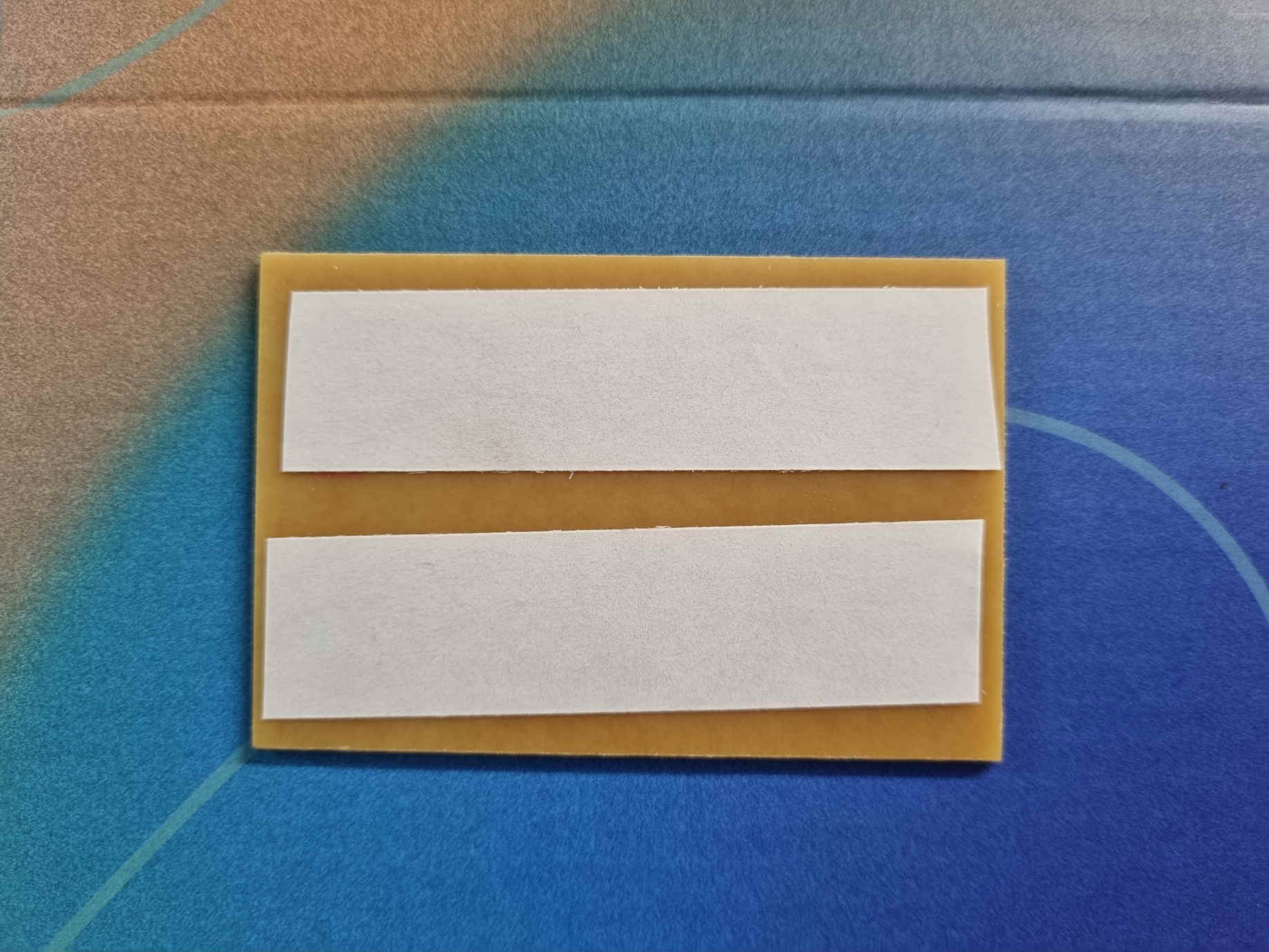
Putting the copper board onto the waste plate
-
The copper boards used was FR4 copper board 2” X 3” and 6” x 4” respectively.
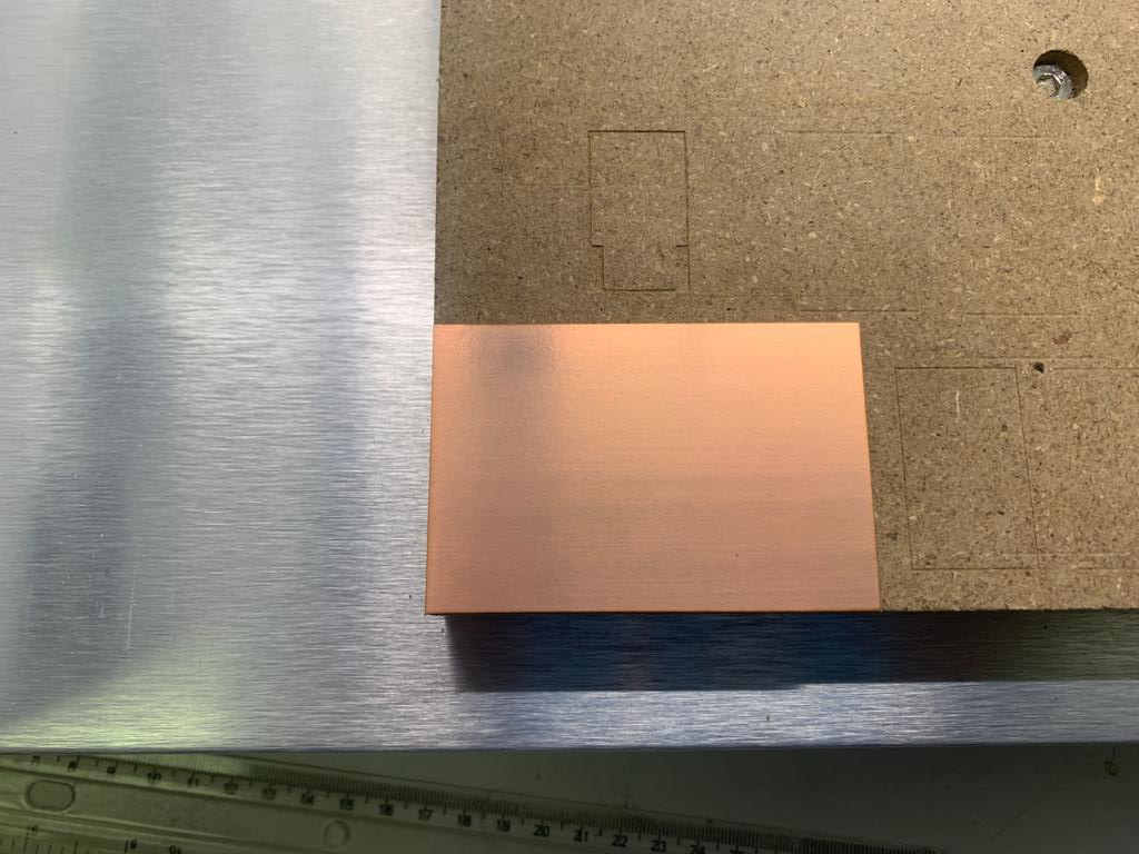
- The copper board was secured to the waste plate as shown in the following picture using double sided tape.
Generating the tool path for tracing and cutting the line test in Carbide Create
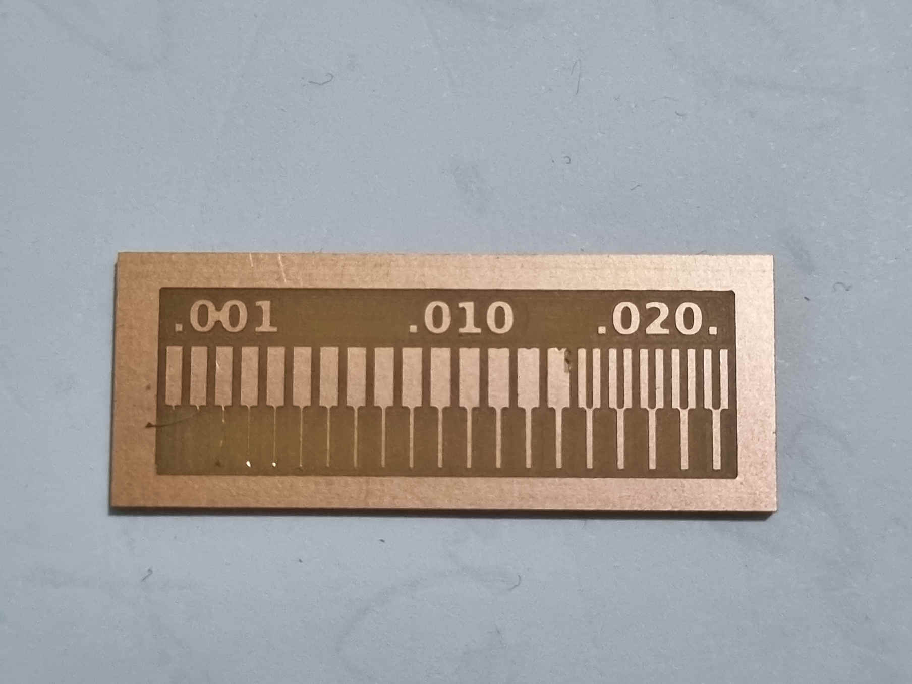
1.The line test was downloaded from the following fab academy webpage:
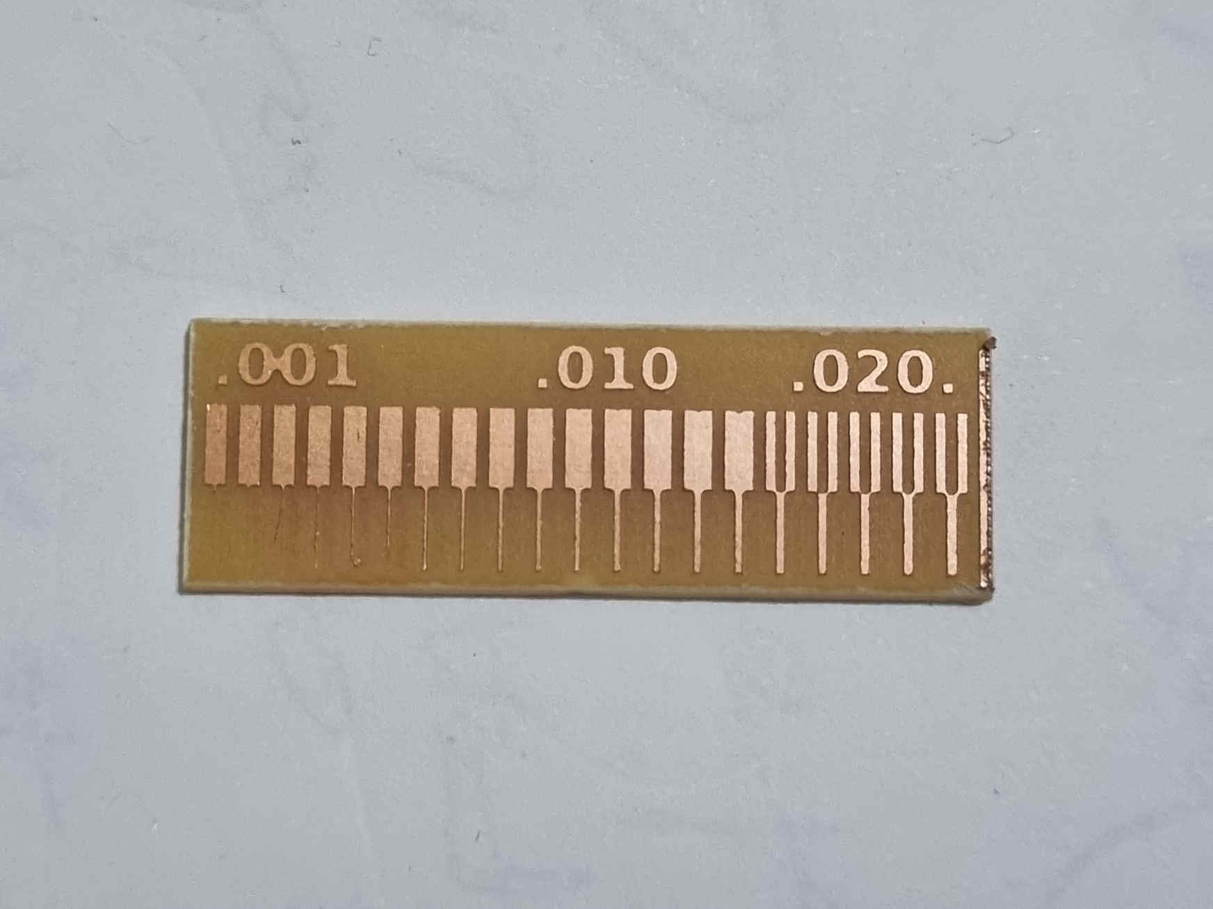
- The traces for the interior and the line test are shown in the image below
2.The file was imported into inkscape which is an open source vector graphics software in a PNG (portable network graphics) format making sure that Embed was selected.
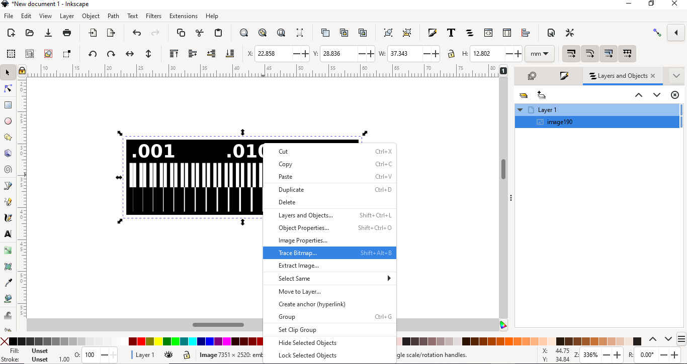
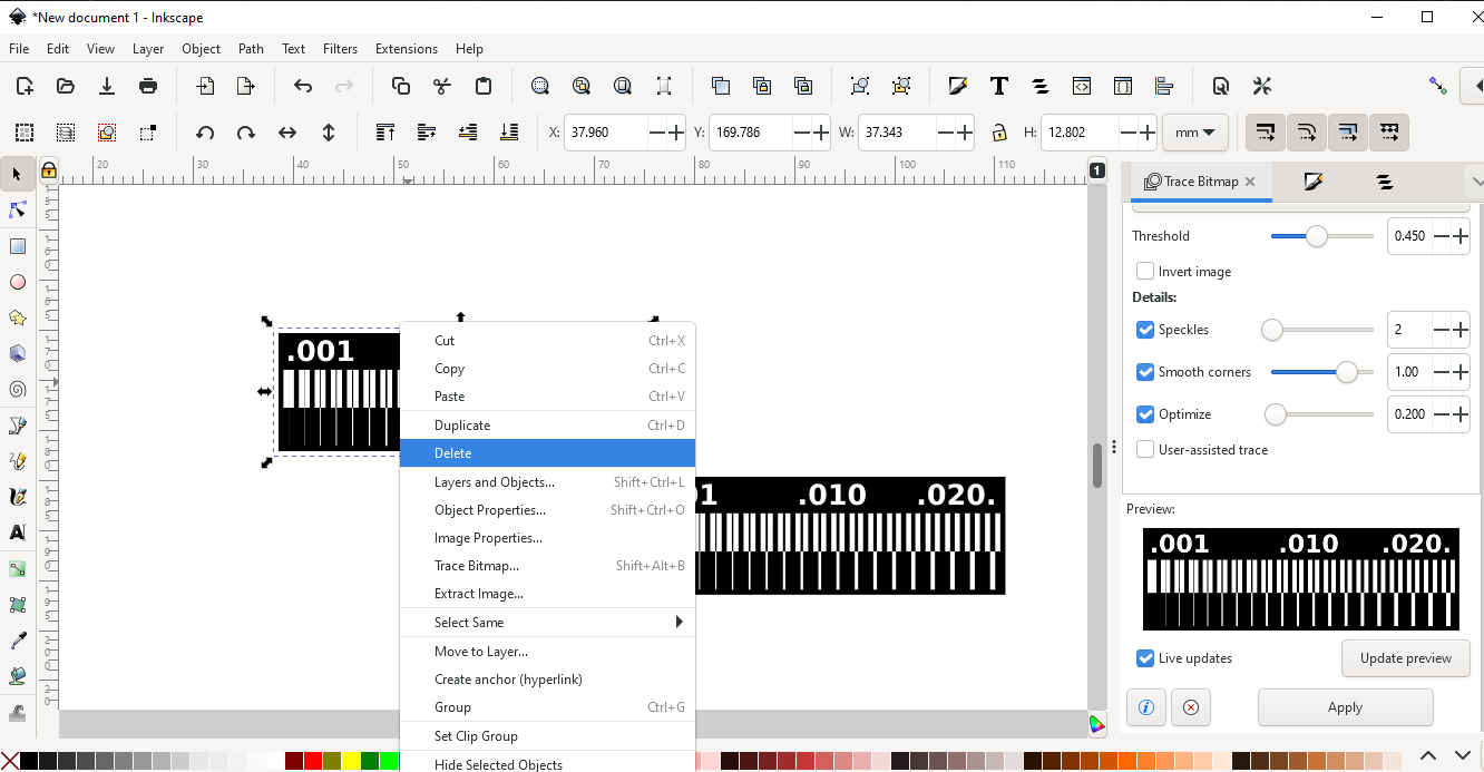
3.It was made sure that the image was selected and then right click on the image and select TRACE BITMAP. None of the setting was altered before clicking OK.
4.In this step we separated the traced shape from the original shape by dragging the traced shape from on top of the original image. The original image was deleted only keeping the traced image.
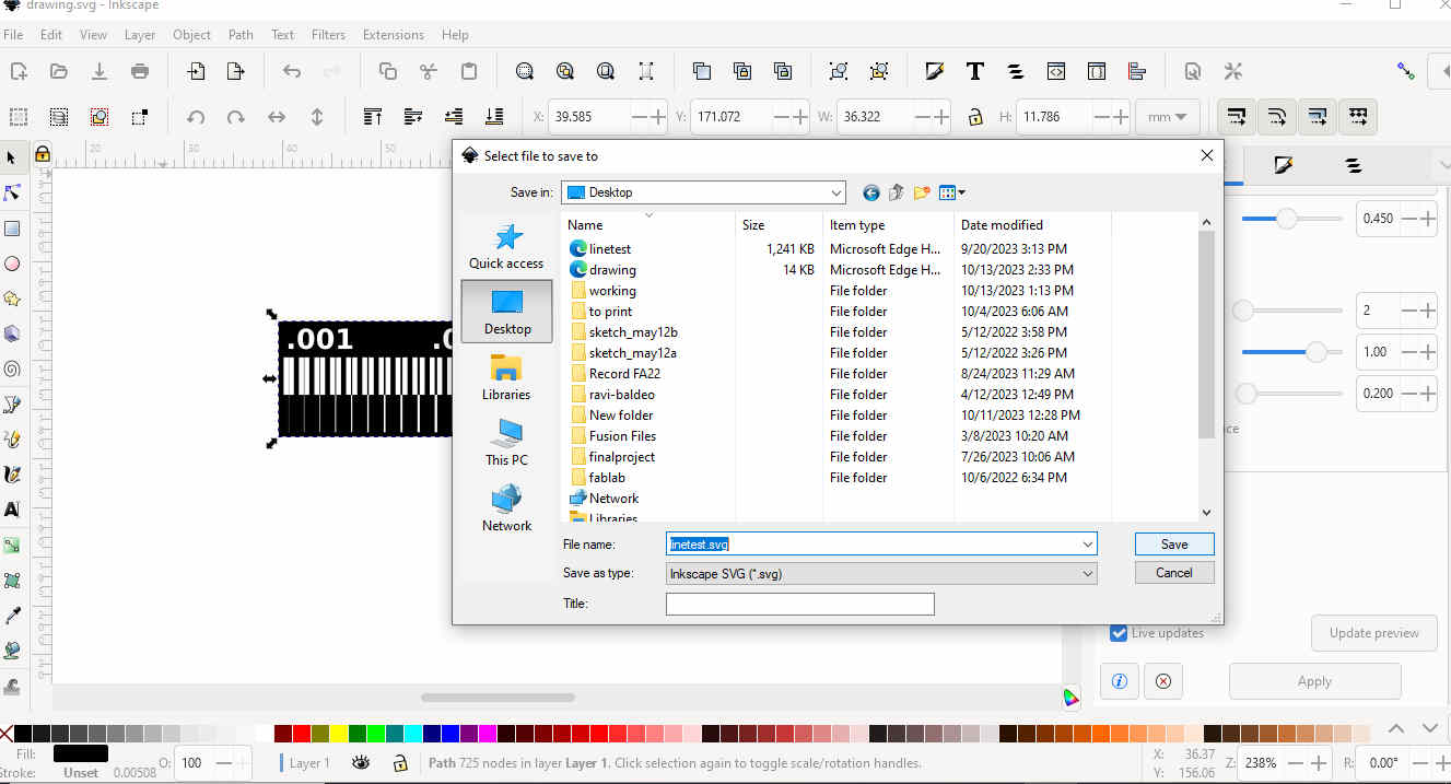
5.The following steps was followed for step 5:
- Now click File > Save as > select the option that says. SVG and save the file.
6.Carbide Create was opened and it was made sure that the settings in the set up corresponds with the settings below:
-
stock size is set to 8in x 8in
-
Stock width is o.5in
-
Material is hard plastic
-
Machine is set to Nomad 3
-
Retract height=0.1000in
-
Toolpath zero set to the lower left
-
Pic(carbidesettings)
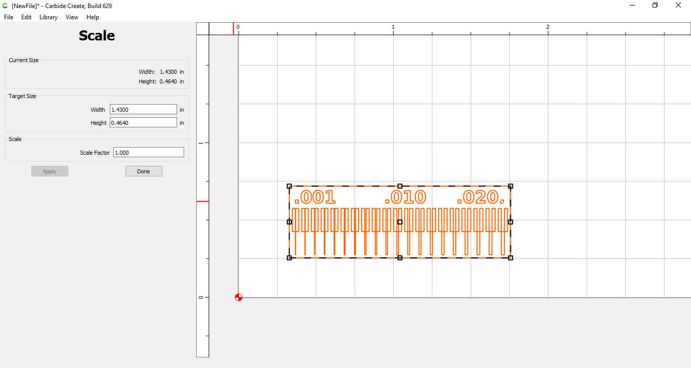
7.The SVG file was Imported that was previously created in inkscape.
- Then we highlighted the SVG file and clicked on scale to ensure that the size of the image is able to fit on the copper board being used.
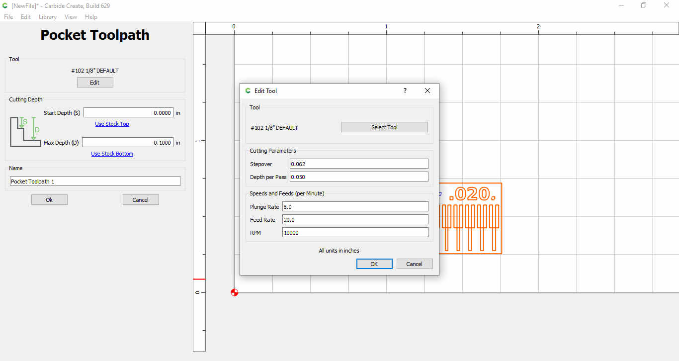
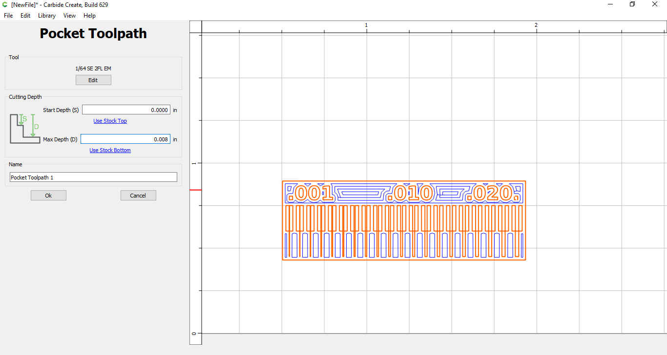
8.Afterwards we navigated to the toolpaths tab and made sure that the imported file is selected then clicked on the pocket tab.
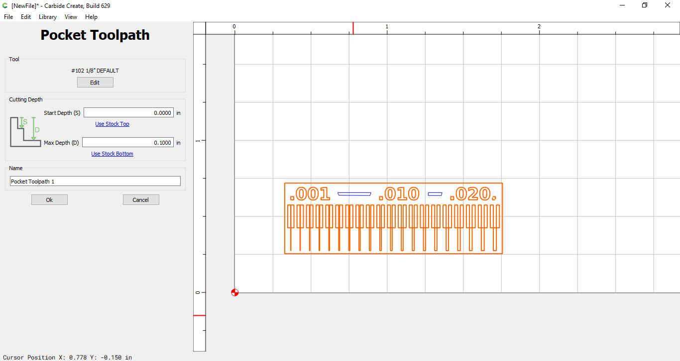
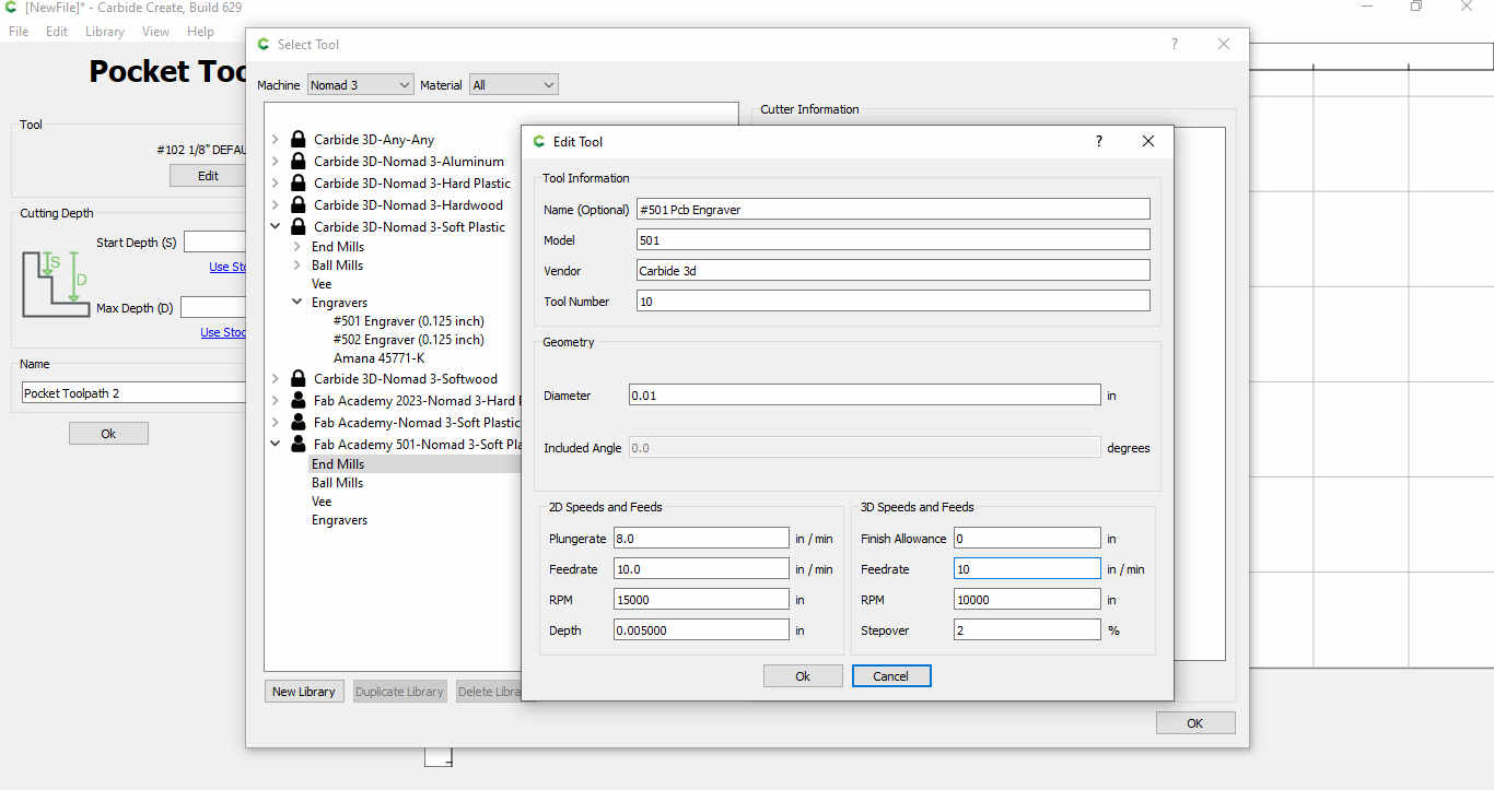
9.Edit tool was selected in the pocket toolpath and then select tool.
- In carbide create the end mill being used (“#501”) is set as an engraver instead on an end mill hence a new tool was created as follows. We went to “Select Tool”, find “#501 Engraver” under “Carbide 3D Nomad 3 Soft Plastic> Engraver.” which showed the parameters for creating a new tool.
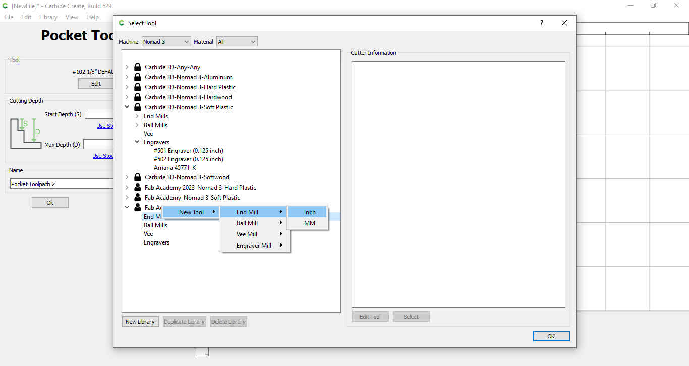
10.Then we went to new library at the bottom left hand corner and created a new category
-
After that the following was done under new category:
-
Right click on “End Mills” and select “Inch” under New Tool>End
-
Mill>Inch.
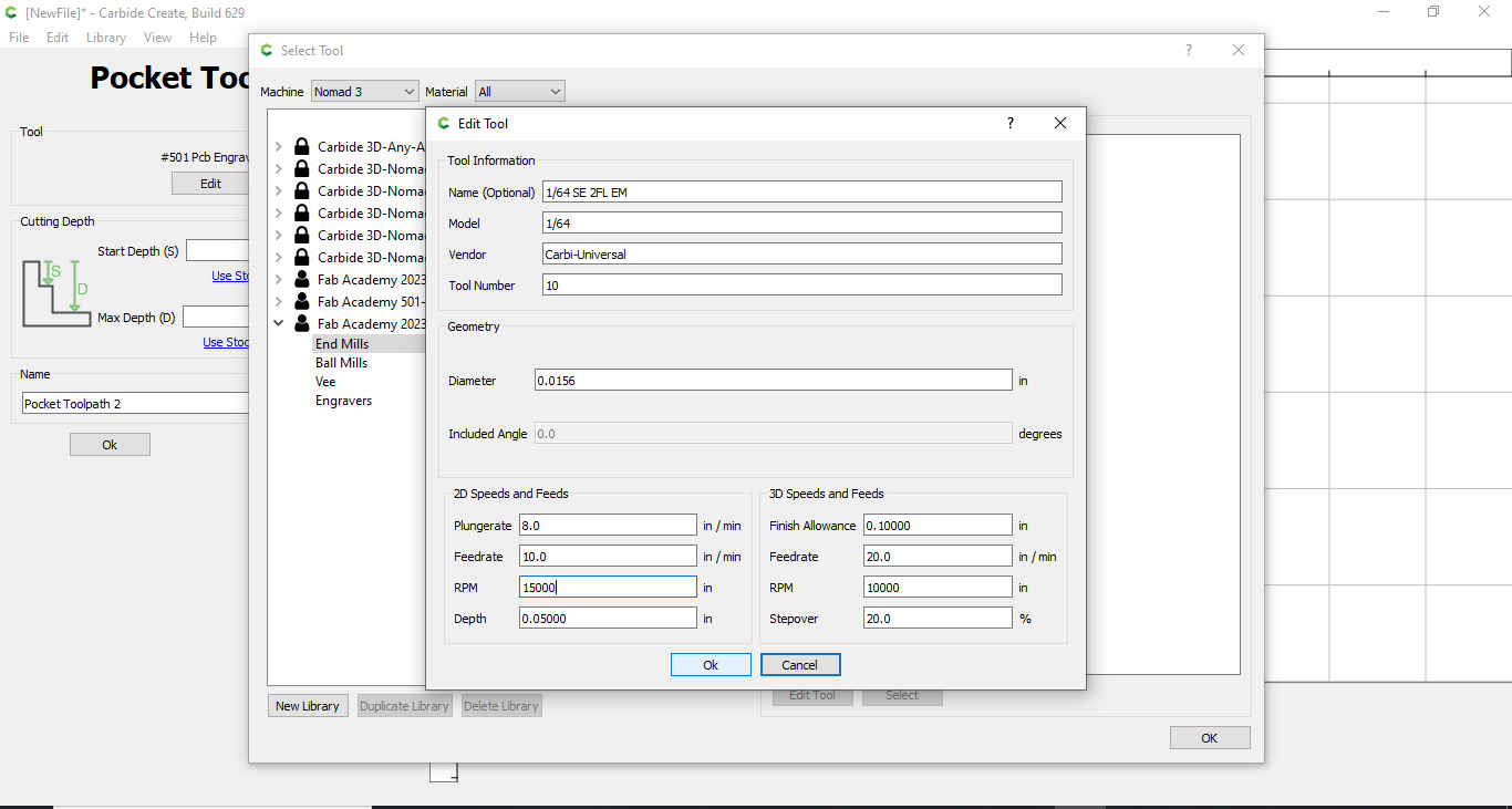
- The parameters was filled out as shown In the picture
- Before the profile was closed depth per pass was copied and paste under max depth (the max depth would be altered to get a thicker or thinner cut into the material) in the pocket toolpath options.
11.The tool path was generated that took out the unwanted copper.
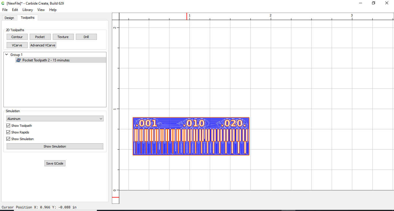
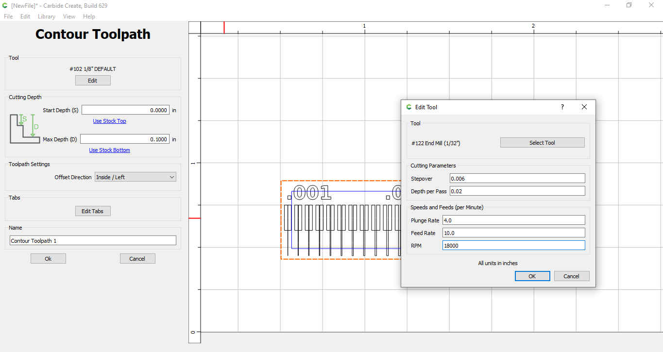
- Now a cut out tool path was created to cut out the copper board created. Only the outer path was selected, then click on contour. The #122 End Mill (1/32”) was selected from the soft plastic nomad 3 library.
The following was set:
-
Depth per pass=0.02in
-
Max depth=0.10in
Tool Used for Pocketing
-
1/64 SE 2FL EM(Carbi-Universal)
-
1/32 LOC
-
1-1/2 OAL
-
Pic (164)
Tool Used for Pocketing
-
122 SQUARE 1/32 2FL (Nomad Tools)
-
0.63in LOC
-
1.5IN OAL

Pocket Settings
|Test 1 | |||| | Test 2 |
|Stepover:0.008| |||| | Stepover: 0.008 |
|Depth Per Pass:0.006 | |||| | Depth Per Pass:0.006 |
|Plunge Rate:8 | |||| | Plunge Rate:4 |
|Feed Rate:20 | |||| |Feed Rate:10 |
|RPM: 18000 | |||| | RPM: 18000 |
|Max Depth:0.008 | |Max Depth:0.006 |
Contour Settings
-
Stepover:0.006
-
Depth Per Pass:0.02
-
Plunge Rate:4
-
Feed Rate:10
-
RPM:18000
-
Max Depth:0.100
Note-All units were set to inches
References
Carbide3D Website Link
Fab Academy Documentation Link