3. Computer Aided design
In this week we were introduced to Computer Aided Design (CAD) software and uses. Most of the software highlighted were open source software while some had paid versions. This week I looked at 2 software, Inkscape & Fusion 360. capabilities.
Inkscape for 2D
Inkscape is a free and open-source vector graphics editor used to create vector images.Inkscape can be used for creating logo’s ,icons,illustrations,infographics and charts as vector images are scalable without a loss in quality.I chose this software becaues it was opensource and had a lot of resources on how it can be used.
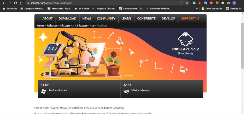
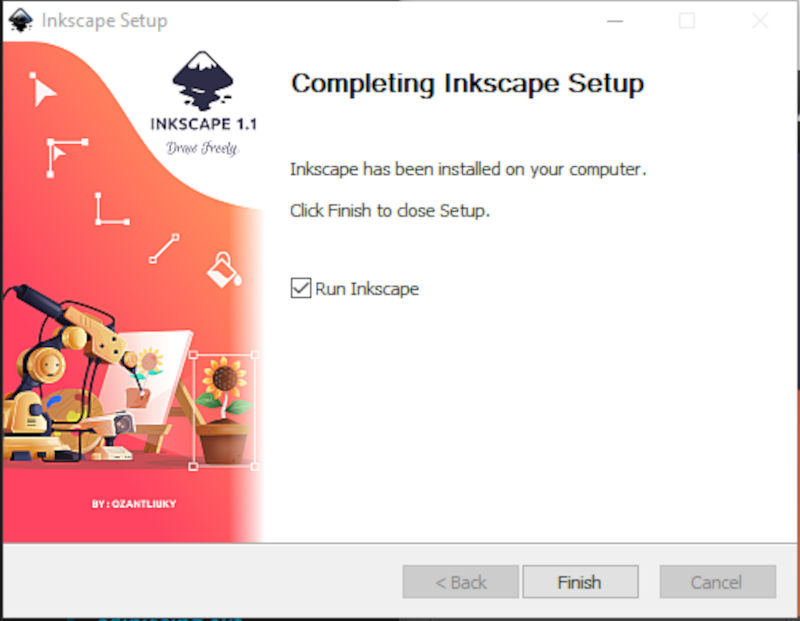
1.Firstly , I downloaded and installed the inkscape software for windows as it is my operating software
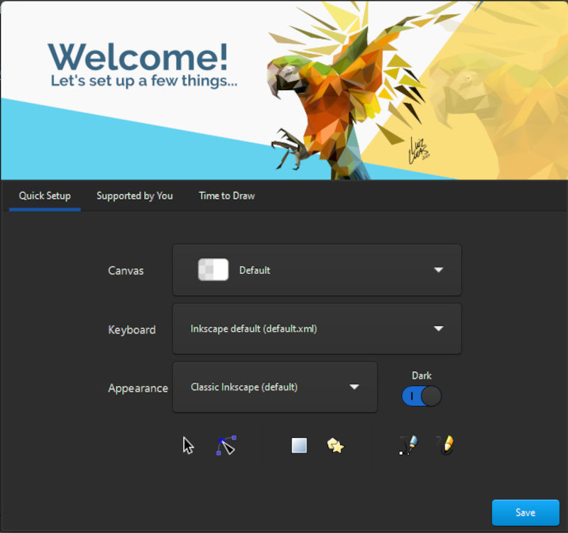
2.The next step was to launch inkscape. When it loads for the first time you will be given the options of choosing a canvas,keyboard layout, appearnce and darkmode.
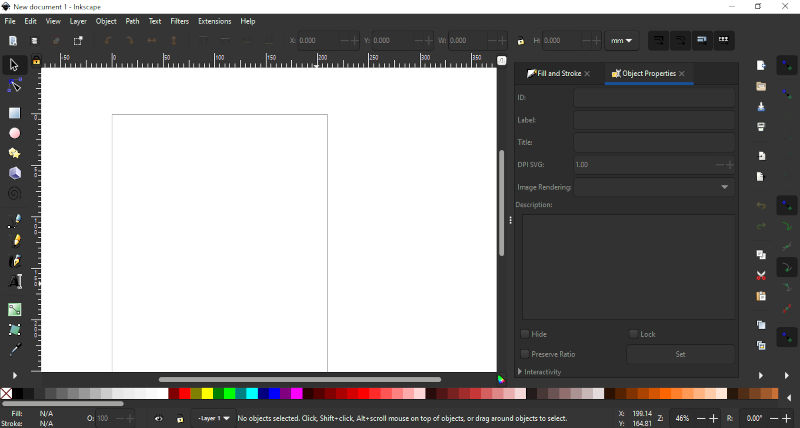
3.When inkscape starts there will be a blank document in the centre, with drawing tools on the left,panels with useful options on the right and color pallette art the bottom.
4.Before starting a design adjust the document page size with document properties.
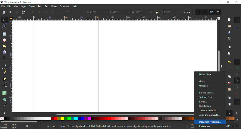
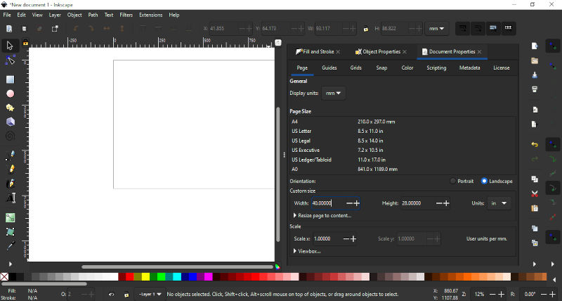
Note. Ensure the the correct units are selected.
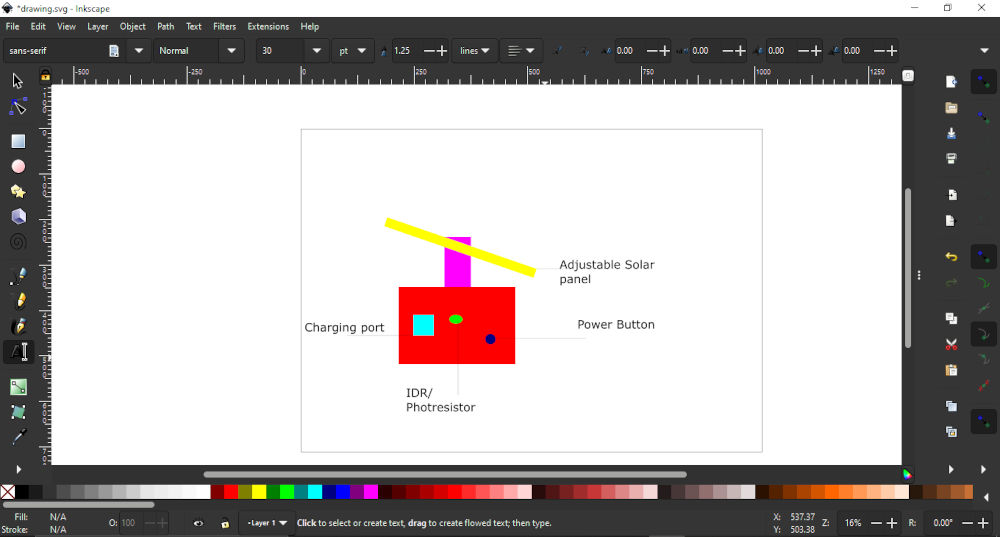
5.As I was looking at creating the sketch of my final project.I started with creating the basic shapes required for the design rectangle, circle and elcipse . This was achieved by selecting the respective tabs on the left panel/ type the command on the keyboard rectangle & square (R),circle and elipse (E) on the keyboard.

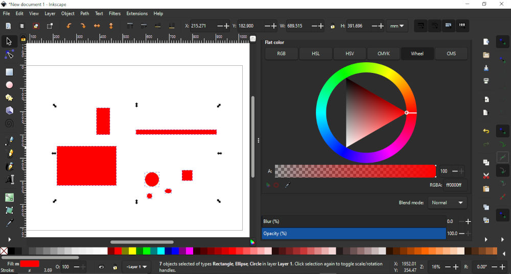
Note. When starting Inkscape for the first time ensure opacity is changed or you may only create transparent shapes.
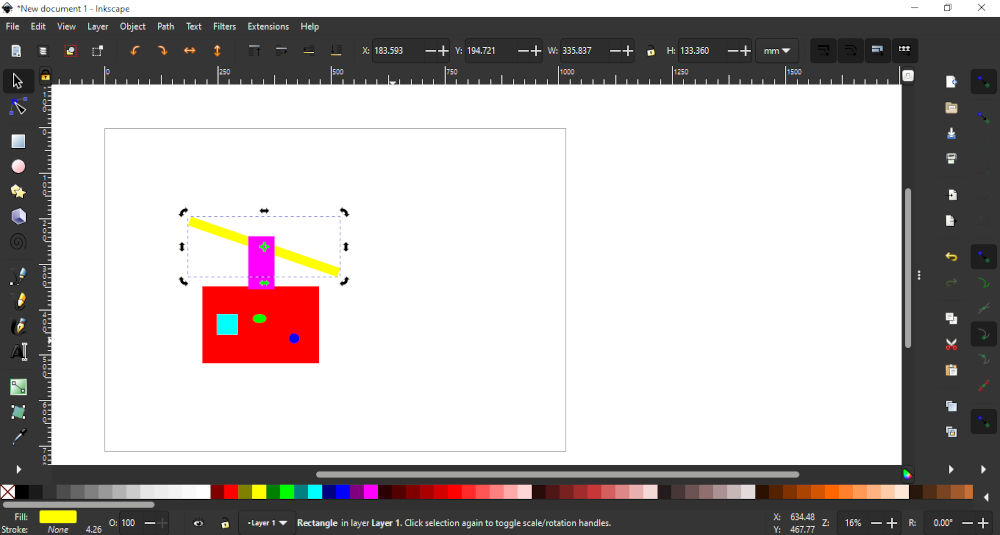
6.a) After creating the shape I needed, it was time for editing. I changed the color of each shape to differniate them from one another. This was acchived by selecting the shape and then choosing a color from the planel below.
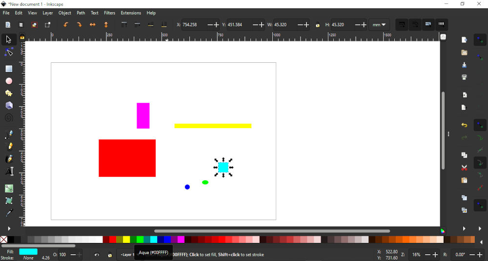
b) The next step was to move the various shape into place.This was achieved by left clicking on the shape once and using the mouse to move the shapes into the correct position.
Note. When you left click on an object directional arrow keys will appear that can be used to resize the object. Also arrow keys can be used to move an object.
c)The next step was to rotate the shape that represented the solar panel. This was achieved by left clicking on the shape twice and rotation arrows appeared. It was just matter of selecting the correct rotation arrow and move the obbject.
7.The next was to ensure that all objects were in the correct place. Unfortunately some objects either blocked other objects. To rectify this I selected the object ,then left clicked on the oject tab on top of the application.In the object drop down I selected lower which moved the object behindthe shape infront of it. If ever I wanted to the opposite I would select raise.
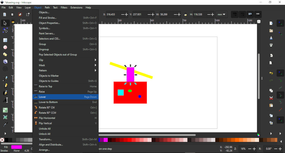
Note. If there are multiple objects Raise to Top or Lower to bottom can be used.
8.After this was done, I decide to keep the objects together. I initailly made the mistake of selecting all the objects , selecting the Path tab and choosing union. This caused all the objects to join together but retained one color (which was not wanted).Therfore , I decided to use another command (group) which was found in the object tab. This joined the objects and retained their orignal properties.
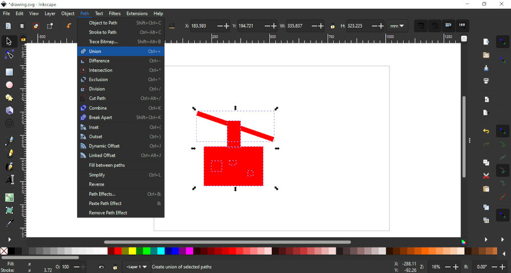
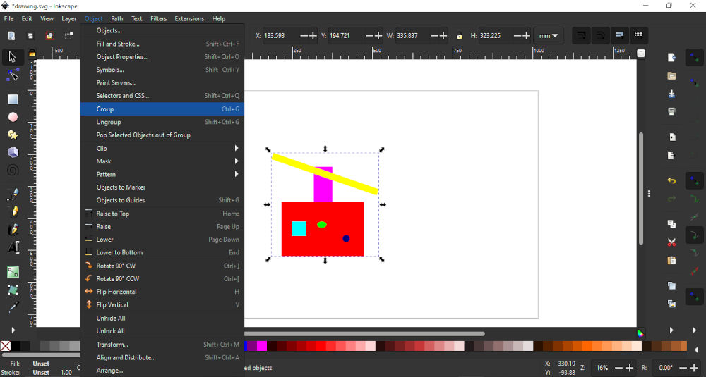
Note. Apart from union there are other useful commands that can edit shapes like difference,intersection,exclusion,division,and cut path.
9.The last thing I did was adding labels to the design . This was achieved by selecting the A on the left panel and clicking on the work area then inserting text.
Note. Text size will have to be adjusted it size not suitable.
Fusion 360 for 3D
Fusion 360 is a cloud-based 3D modelling, CAD, CAM, CAE and PCB software platform for product design and manufacturing. I chose Fusion 360 becuse I was familar with AutoCAD and believed it would have the smallest learning curve as both software were owned by the same company Autodesk.
1.The first thing I did was to get the software set up to be used. I requested a licencse from my instructor went throught the steps of downloading the software from the companys website.
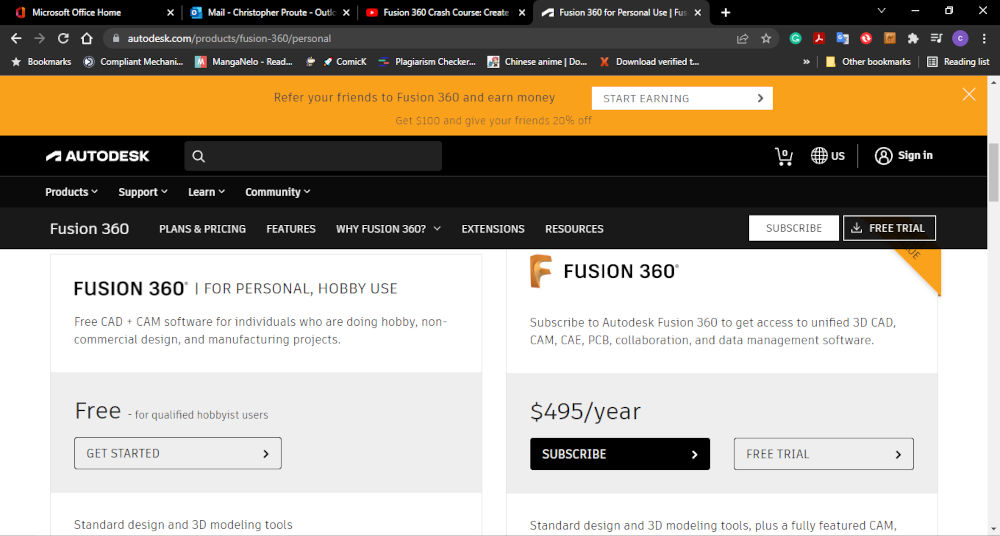
Note.When going to the website to download the software you will have toi setup indicate the type of user you are if you want to use it for free.
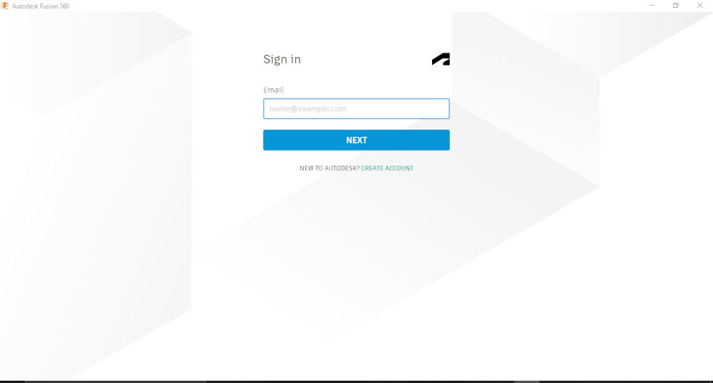
2.After the software was down loaded and installed I opened the software.Then enter the login credentials for your account(username &password).When login is successful the software will open.

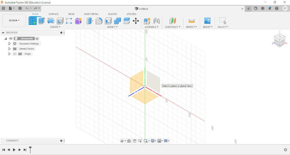
3.When the applications open you will see a blank space which is your drawing area .The top has a buttons that change depending on the command you selected.The left has the project tree which reflects what is being created.The buttom has the timeline which tracks everything that is done and a few other controls .The top right corner is a cube for changing your viewing perspective.
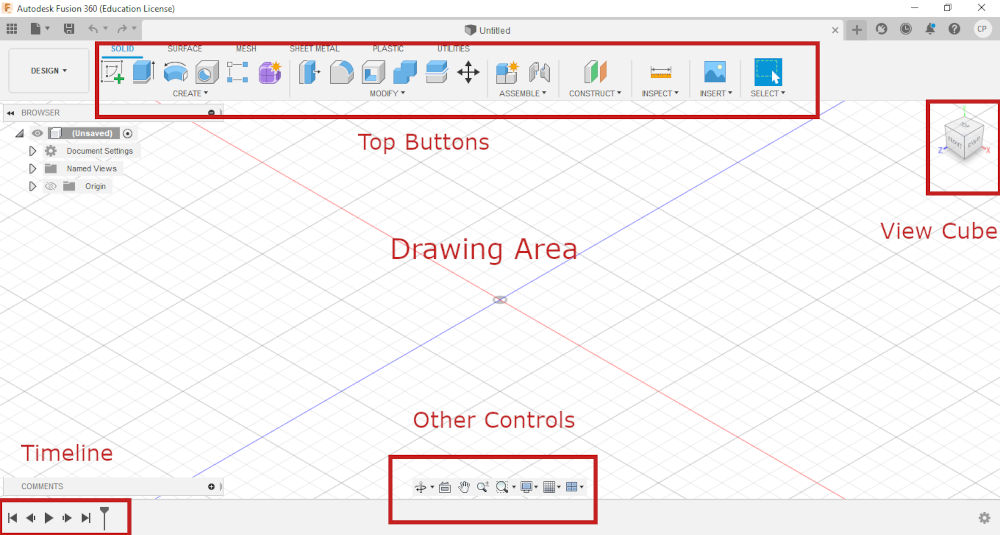
Note.Some buttons have a drop down menu with multiple commands.Timeline can be rolled back to make changes.The view cube can be clicked and dragged or a part selected to change the orientation.
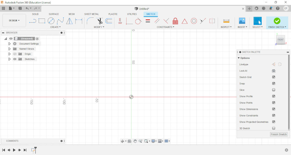
4.When starting a drawing for the first time you will create a sketch which is found at the top.This sketch can be used to make either 2D or 3D objects.After sketch is selected it will ask you to select one of the 3 plains provided.As a plain is selected drawing mode will activate and the commands will change at the top.
Note.A sketch can also be added to a face of an object.Also not that commands can be used by entering them in the keyboard.
5.As I am modeling my project sketch created a square to represent the overall shape of my model. Therefore, I selected the center rectangle command at the top and placed it at on the drawing area.

Note.Before starting sketch set your units by selecting document settings on the project tree.
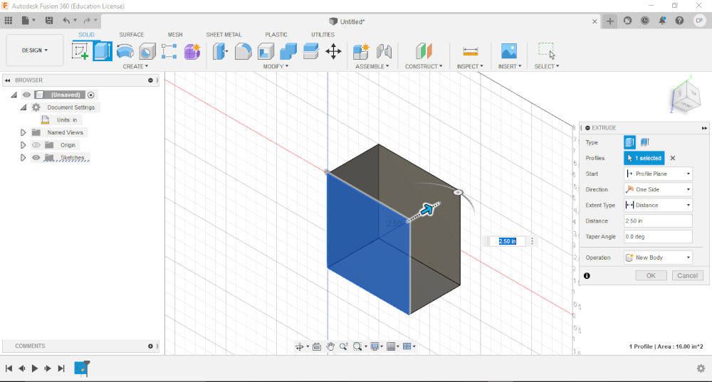
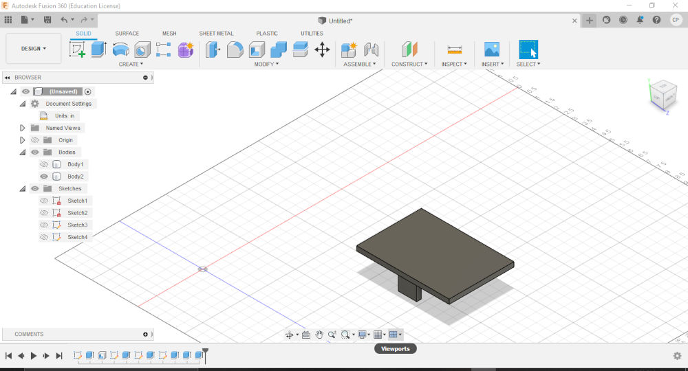
6.The next step was to extrude the shape that was greated. This was achieved entering the e for extrude command and creating a 3D object/body.
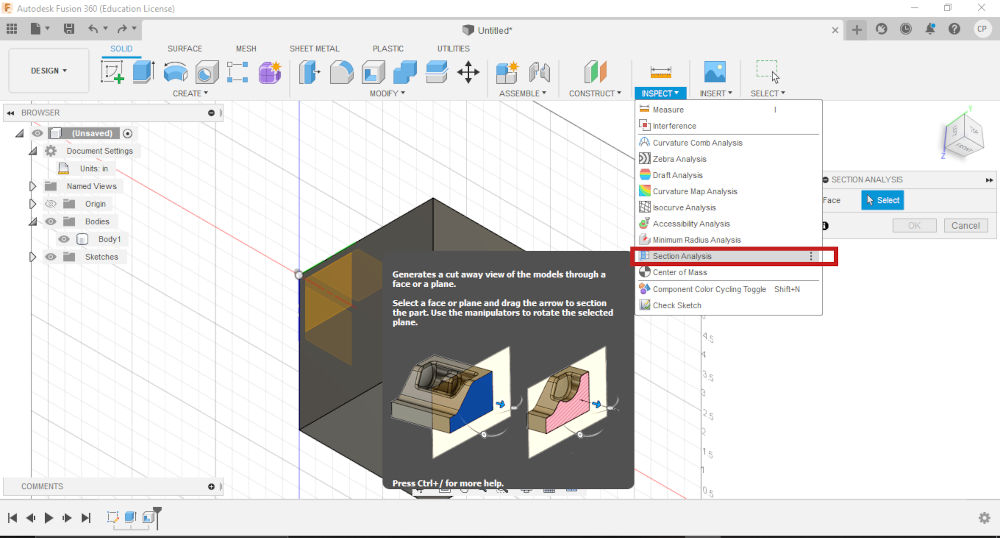
7.Then I performed another operation which would make the body hollow. This command was shell.

Note. Either face or body can be selected
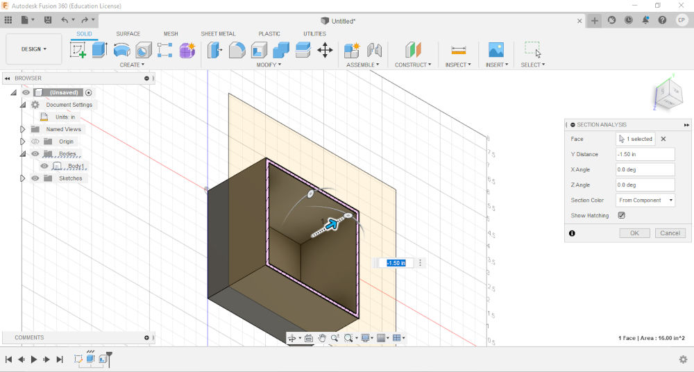
8.To ensure that the shell was succesfull ,I performed a section analysis to confirm that the body was hollow.
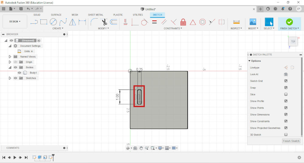
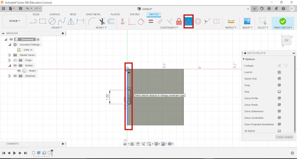
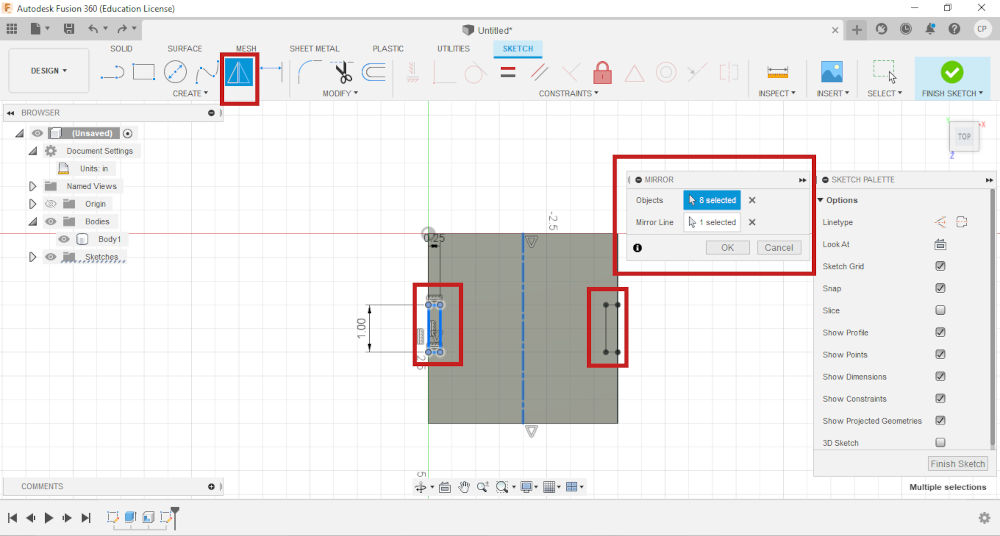
9.Then I created another sketch on a face of the body. I then used constraints to place it athe midpoint of a edge. Then I created a centre line and mirrored it on the opposite side of the sketch . Both sketches where then extruded.


10.Then I created the bar the will support the solar panel for my design.This was achived by creating a new sketch and extruding it.
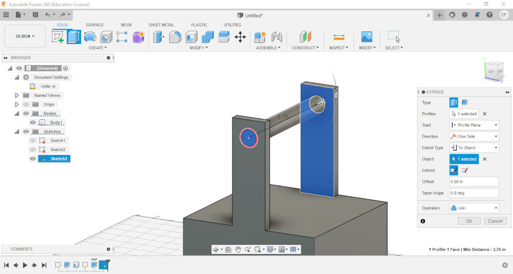
11.Then I created the solar panel and braket to attach to the bar
Note.On the project tree parts can be hidden to work on a specfic part of the design.
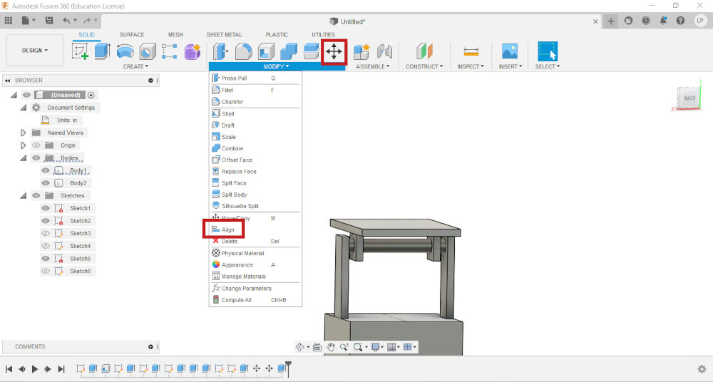
12.Then both parts were placed together. This was achieved by using the align command and the move command
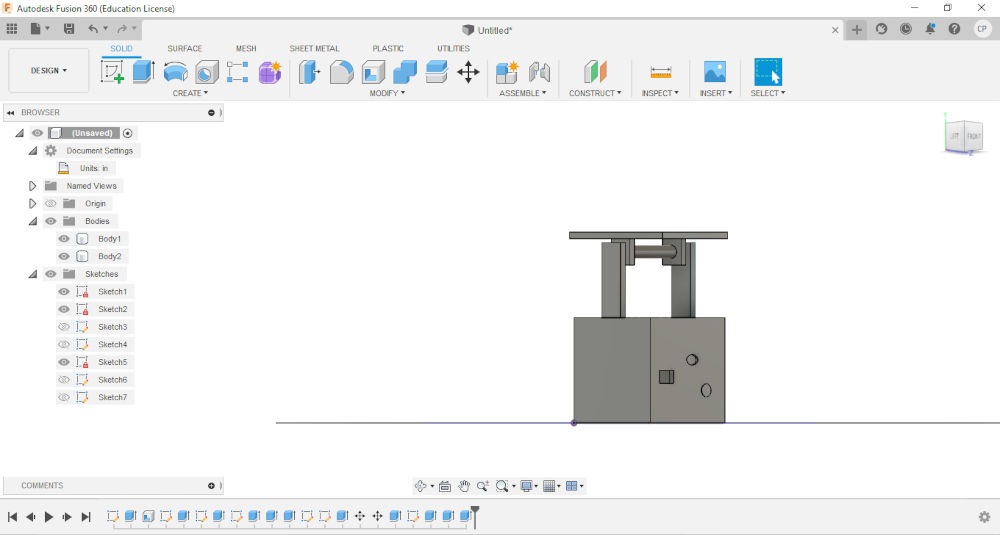
13.Then I created some features that would be placed in the front of the design.This was acheived by doing a sketch on a face and extruding them.
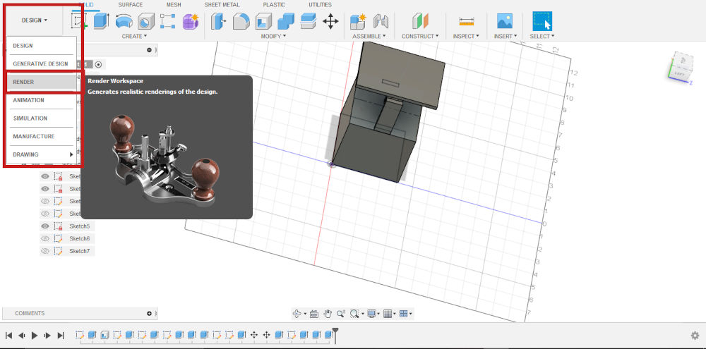
14.At this point I tried to render the design. Before , I started I saved a copy just in case something went wrong and when into the rendering environment.
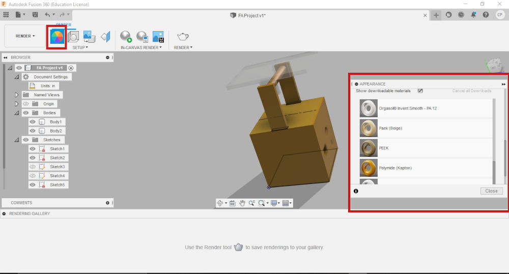
15.Then I changed the apperance of my model by adding different materials.
16.After this I changed the scene setting enviroment to photobooth to get a beeter look
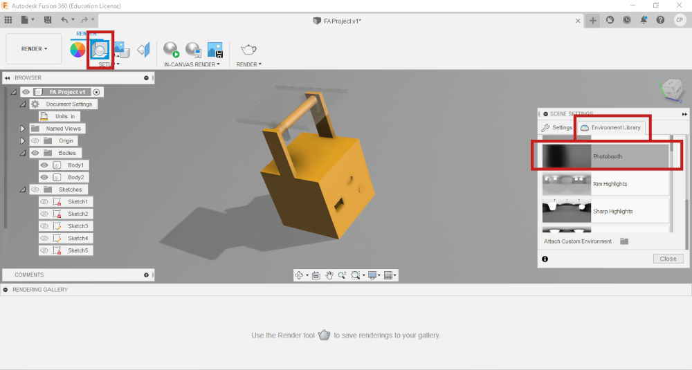
Note. There are several enviroments to choose from based on your preference.