12. Output devices
For this week’s assignment, we looked at Output Devices .This week looked at the following:
Group assignment:
-
Measure the power consumption of an output device.
-
Document your work on the group work page and reflect on your individual page what you learned.
-
Group Project Link
Individual assignment:
- Add an output device to a microcontroller board you’ve designed and program it to do something.
Group Assignment Reflection
The power consumption of output devices must always be taken into consideration as it will affect efficiency.Some common output devices are motors,soleenoids, relays and LEDs.Motors can be considered as a device which consumes a lot of power while LEDs are efficient at higher brightness levels they can also consume a considerable amout of power.
-
Type of device: a device with a motor will consume more power than LED.
-
Load: a motor used to lift a heavy load will cosume more that a motor used to lift a light load.
-
Operating conditions: motor operating in a hot environment will consume more power than a motor operated in cool environment.
There are a number of ways to reduce the power consumption of output devices which include:
-
Using efficient devices:choose output devices that are specifically designed to be efficient. For example, brushless DC motors are more efficient than brushed DC motors.
-
Improving the design:improve the design of output circuits to reduce power consumption. For example, use pulse-width modulation (PWM) to control the power output of motors.
-
Using power management techniques:use power management techniques to reduce the power consumption of output devices when they are not in use. For example, use sleep modes to put motors into a low-power state when they are not needed.
Useful student page Ashod Bzdigian
ATtin1614
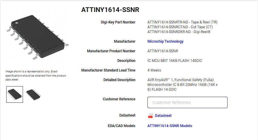
1.Firstly, I opened Fusion360 and in the file drop-down menu, I selected new electronics design. Then I selected new schematic and I began adding the components I would need for the circuit.
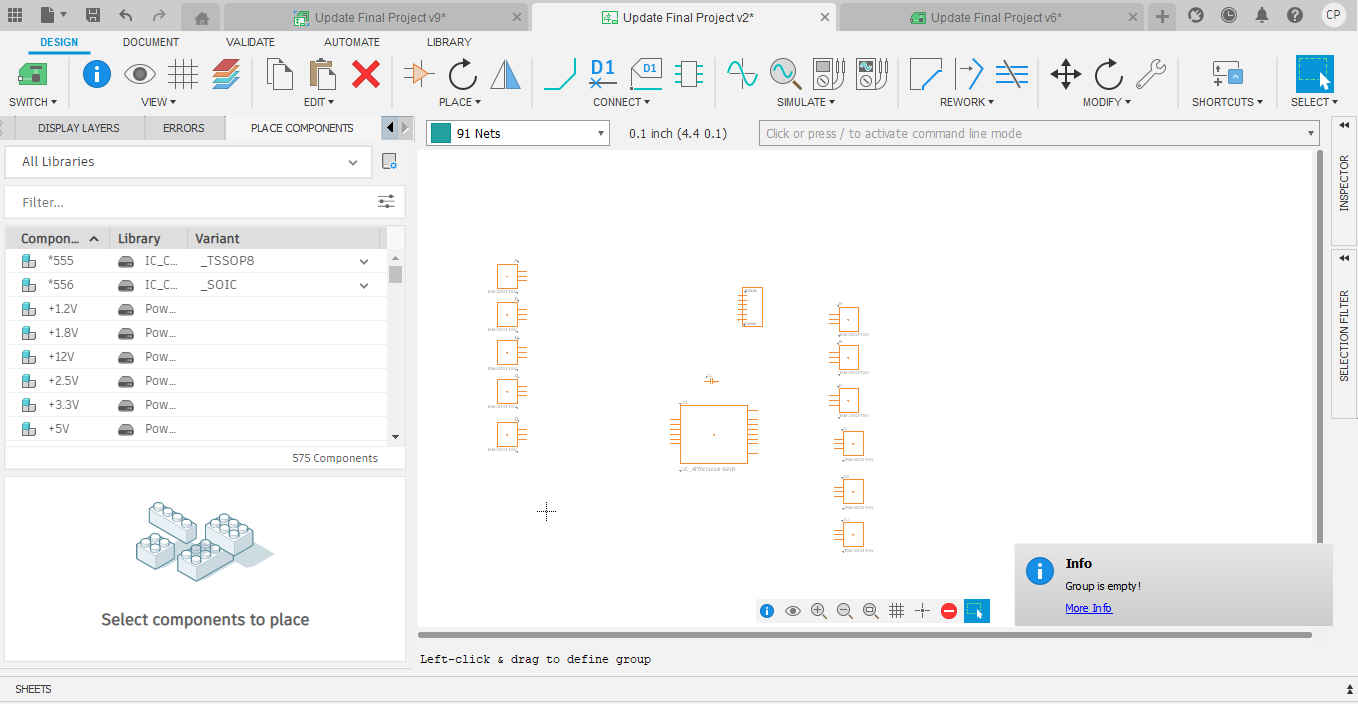
Note. Components may not be found from simply searching but looking creatively.
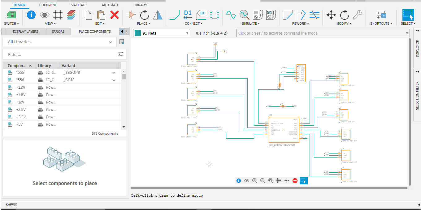
2.Then I placed the connections between components.
3.Then I created my PCB board by selecting switch to PCB document.
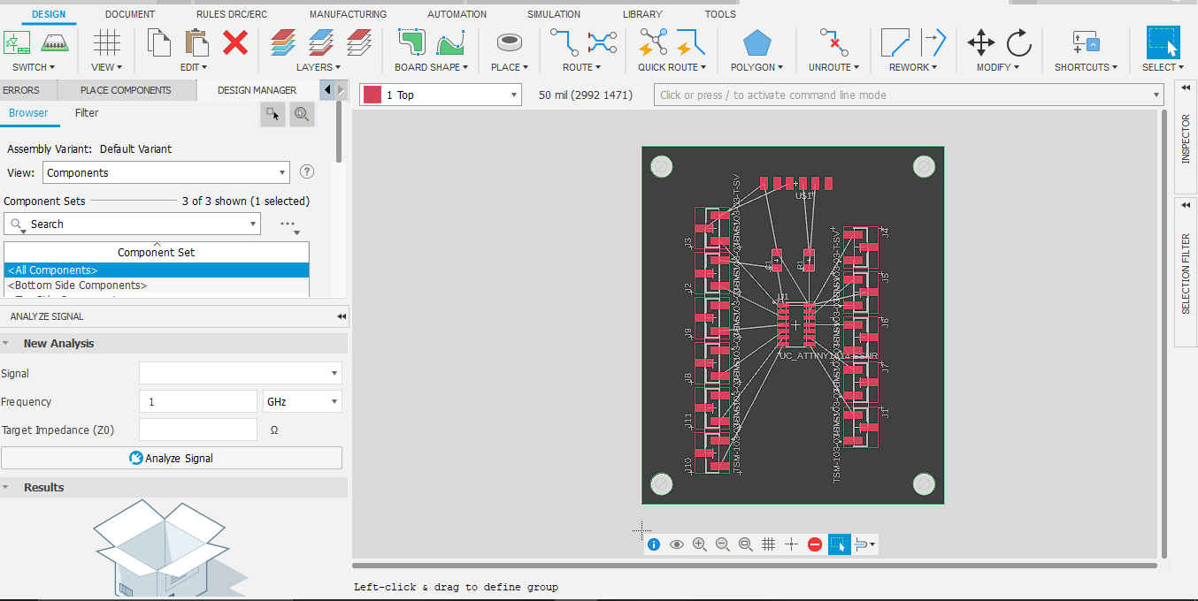
Note. When entering the PCB document, all components will be placed and have ghost traces.
4.Then I ran the autorouter using the design rules to create the traces for my board.
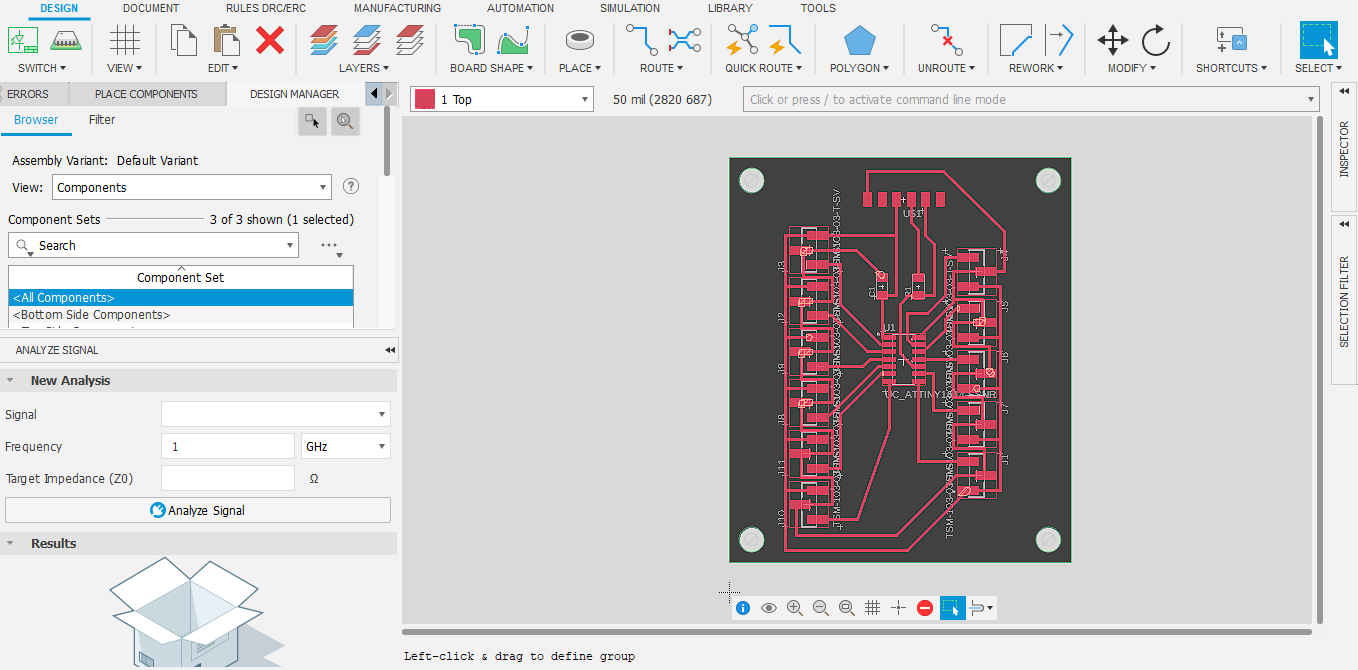
NB. Select the route that is at 100% or select the route that you like and make chnages if required.
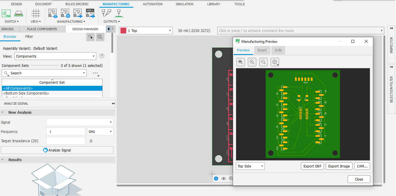
5.Then I selected CAM Preview to view the different layers of the PCB and exported the toplayeras a DXF.
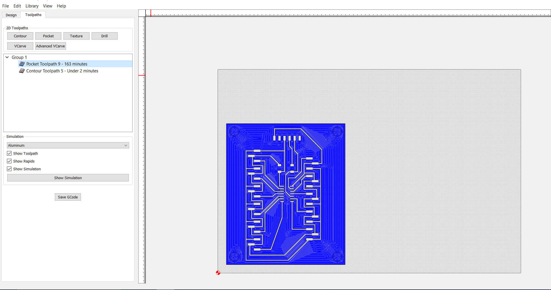
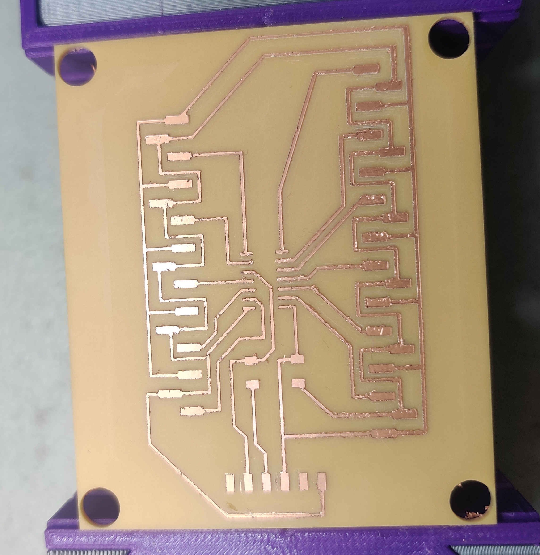
6.Then I went to the milling machine and created the board with traces.software which runs our precision mill and set the dimensions for the board I would be milling.
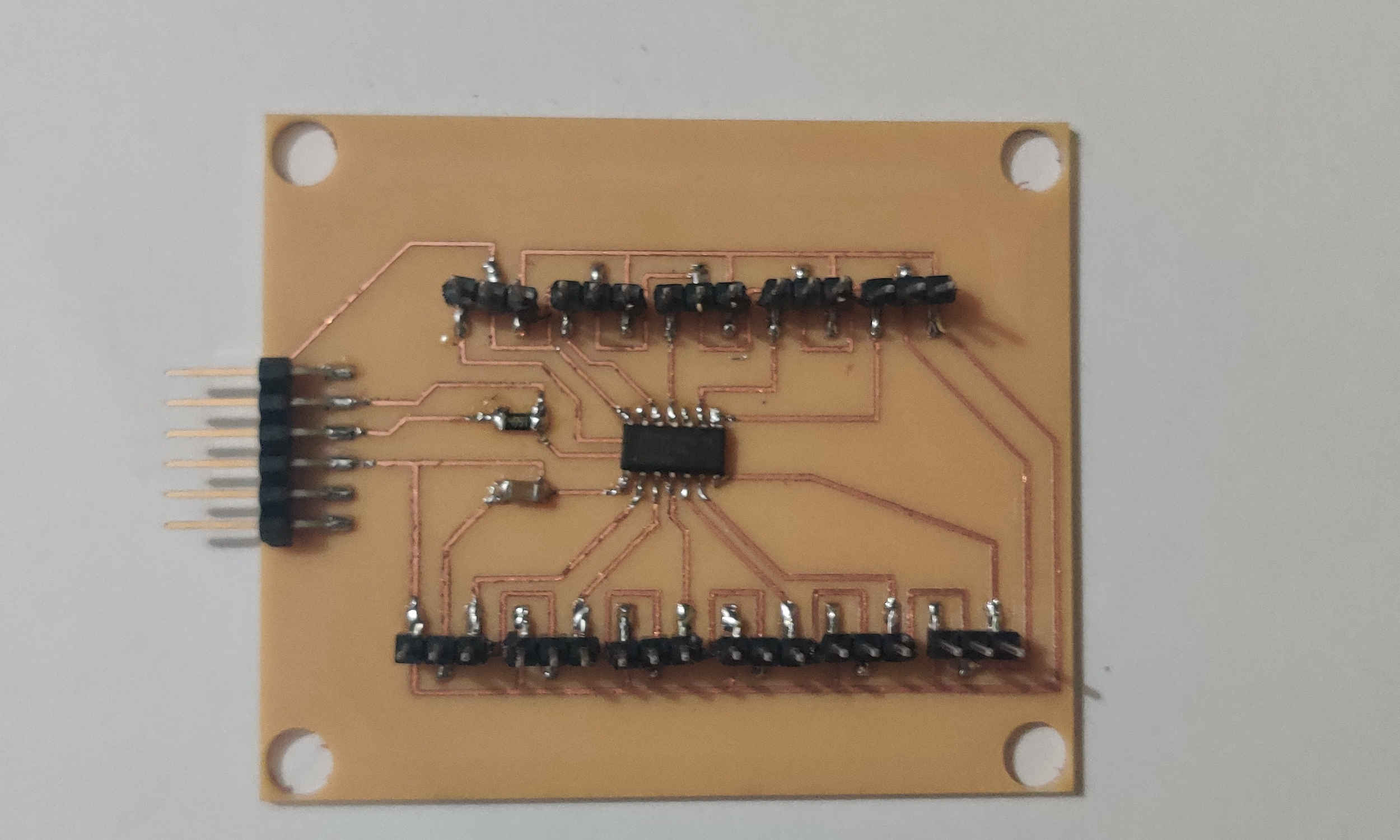
7.Then I soldered the components on the board.
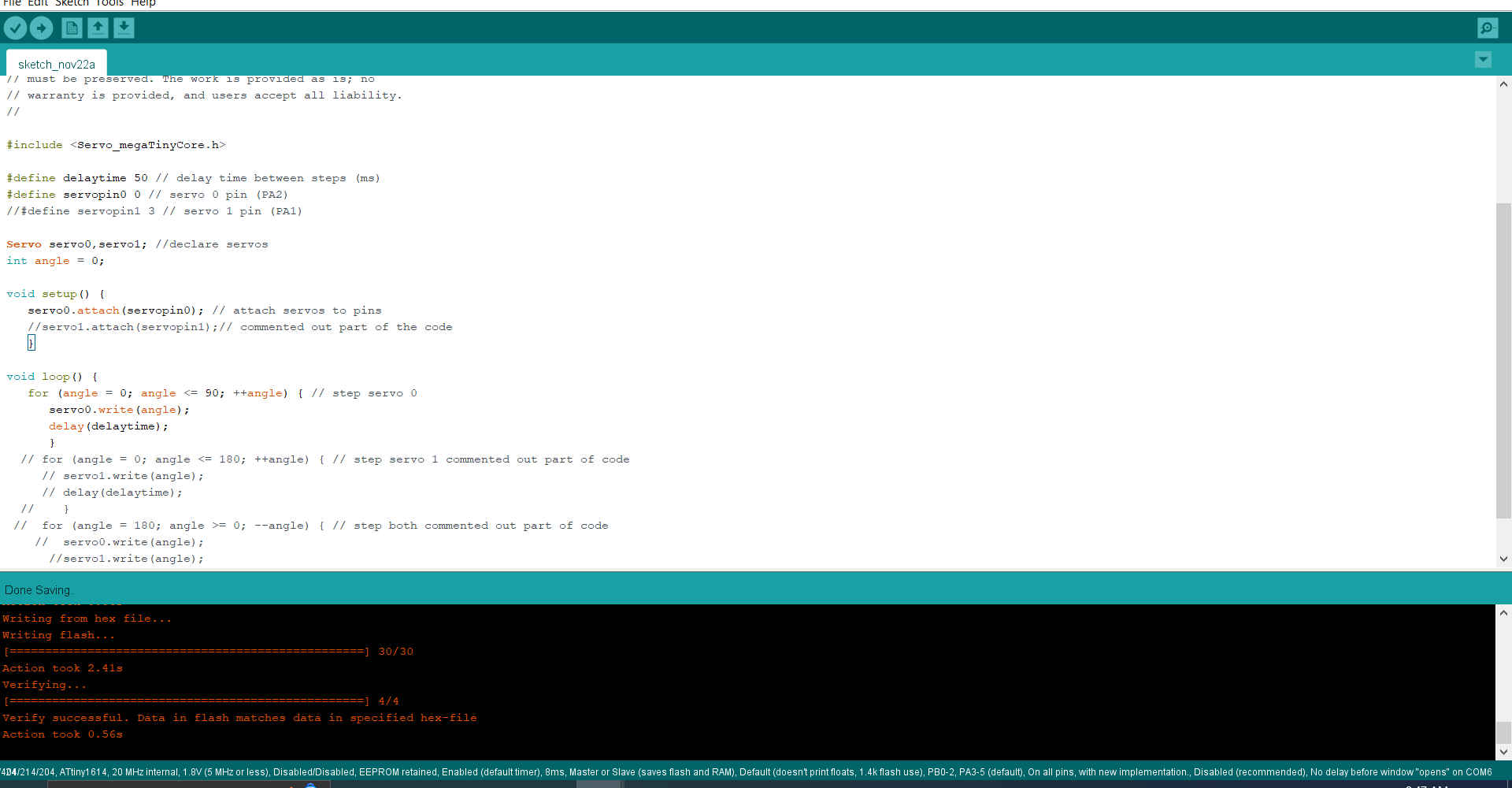
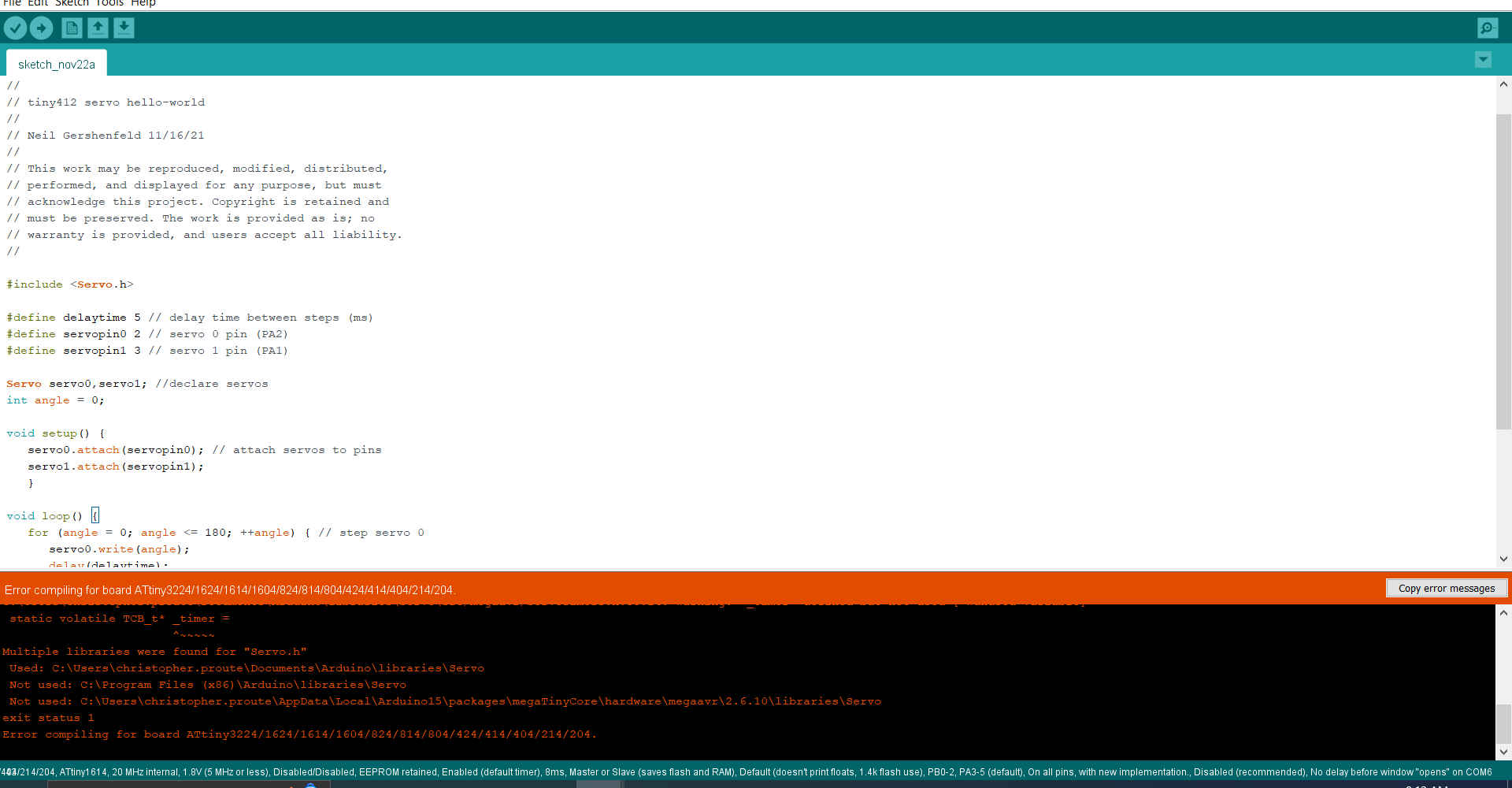
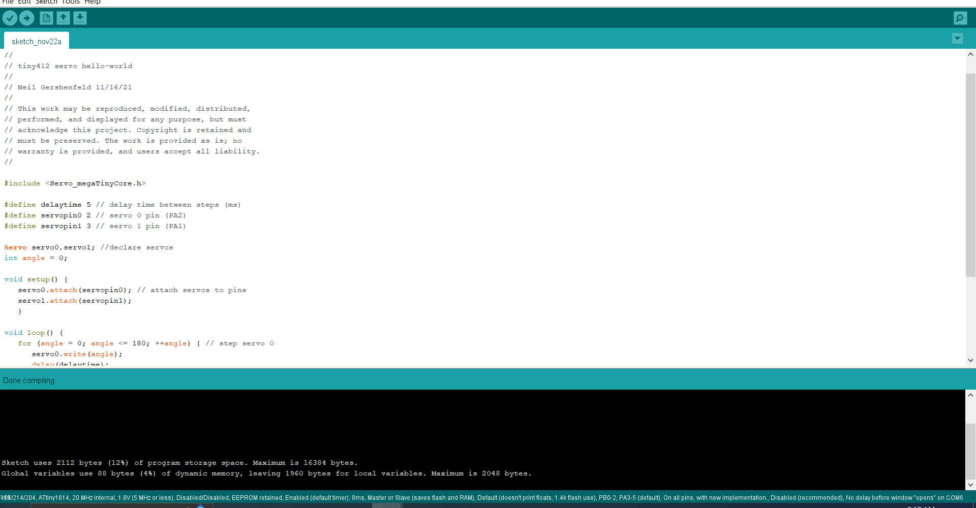
8.Then I went to arduino ide where I reviewed the code created by Neil Gershenfeld. Unfortunately I got an error when I tried to verify the code. After some trouble shooting I found that my servo library for my board manager was named differently and when this changed it allowed the code to be verified.As my code only had 1 servo I commented out the parts of the code that related to the second servo.
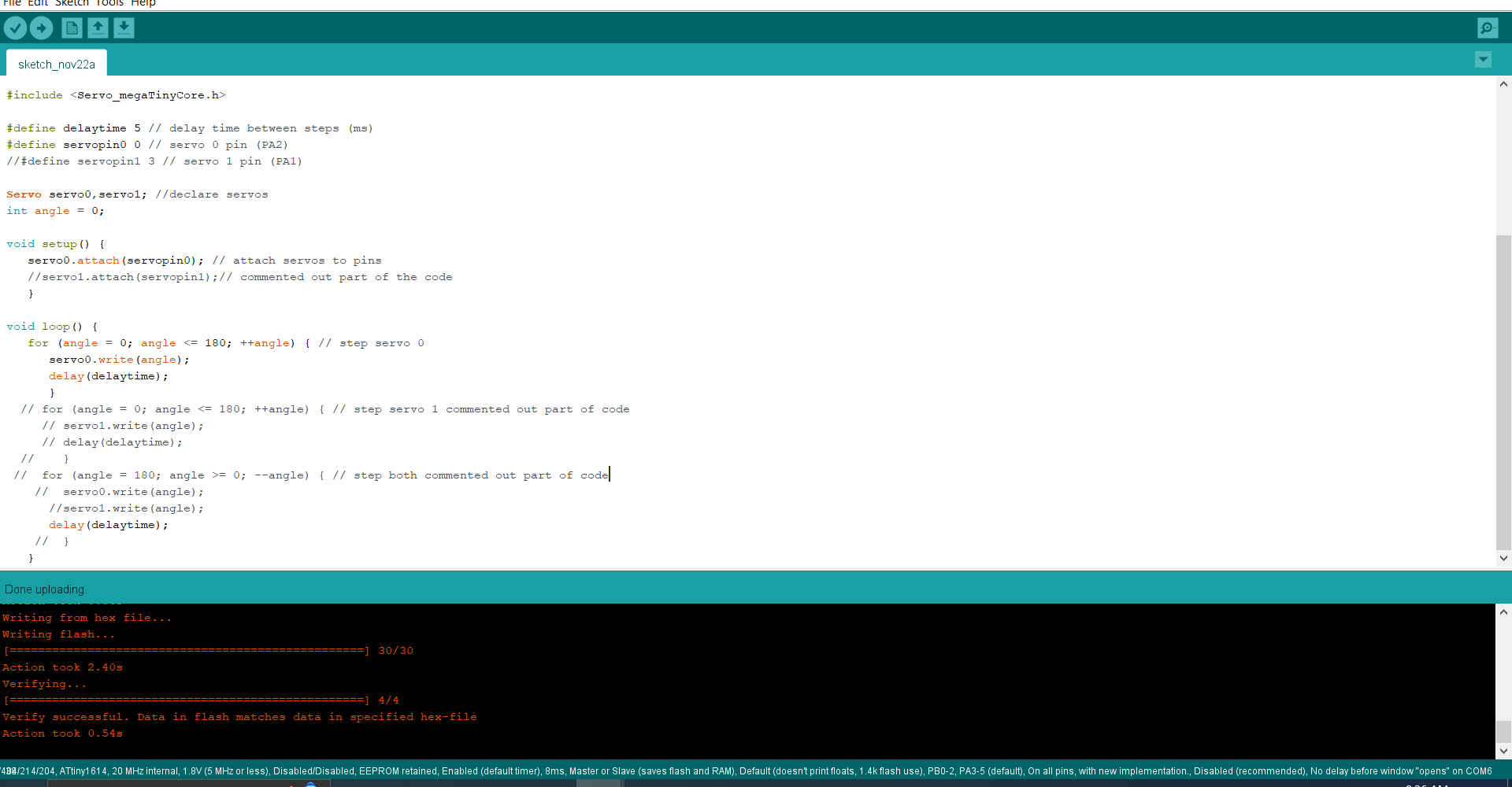
9.Then I modified the code to see the effect it would have on the servo by changing the angle and delay time.