8. Computer controlled machining
For this week’s assignment, we looked at Computer-Controlled Machining. The group assignment was to complete the lab’s saftey training.Test runout,alignment speeds,feeds, toolpaths of the lab’s CNC Router and document the work done.While the individual assignment was to make something big which will incorporate 3 aspects design ,mill and assemble.
Group Assignment
The group assignment can be found on the link below
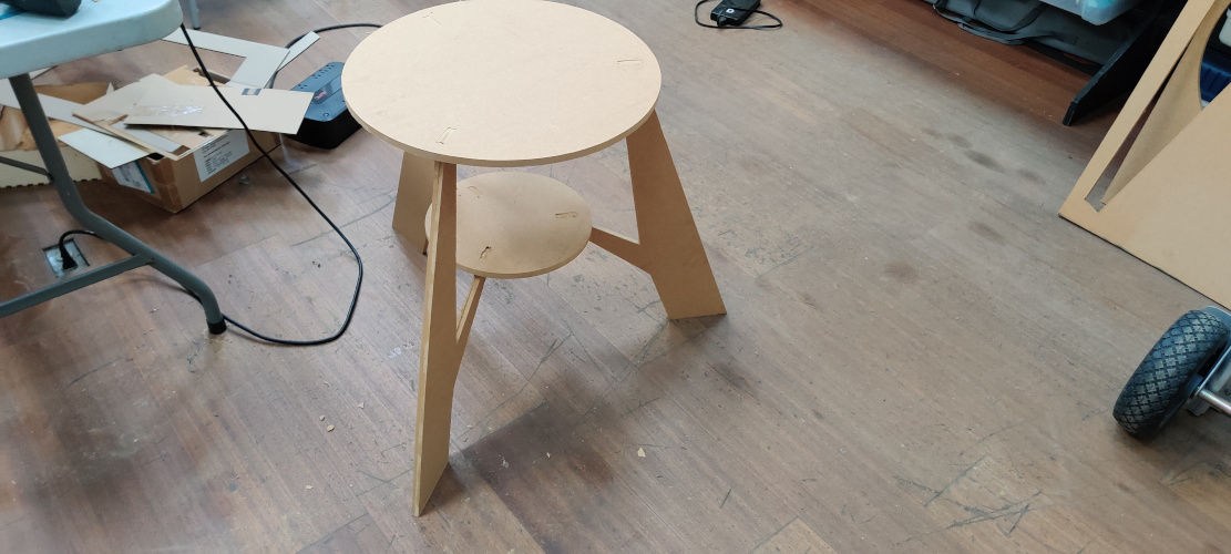
For this week’s assignment I decided to make a table using Fusion 360. Hopefully, it comes out ok.
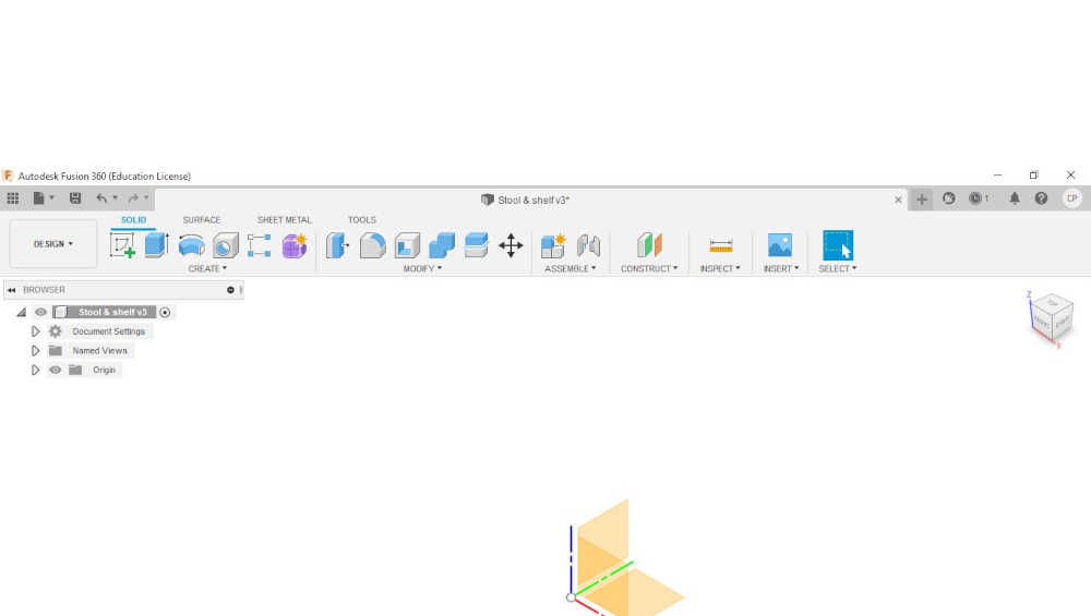
1.For this design I chose to use Fusion 360 as the software of choice. One of the first things that should be done before starting to draws is saving the drawing. This will help you later as it will keep track of any version changes.
2.Create parameters. These will be used to modify the design should changes have to be made later.

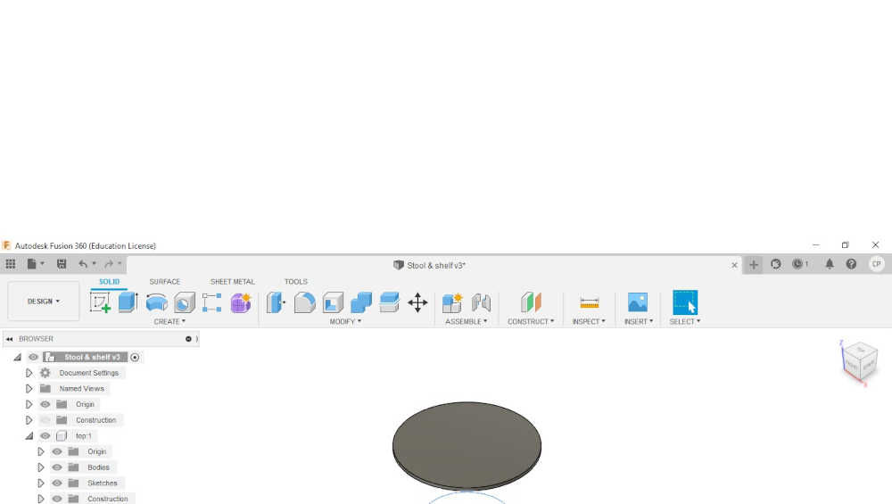
3.Create a new component. This will be used for the top part of the design.
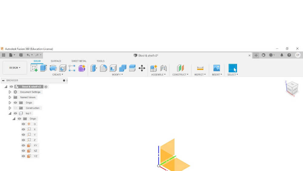
4.Create an offset plane. This will be created from the ground plane and the distance will be the height parameter.
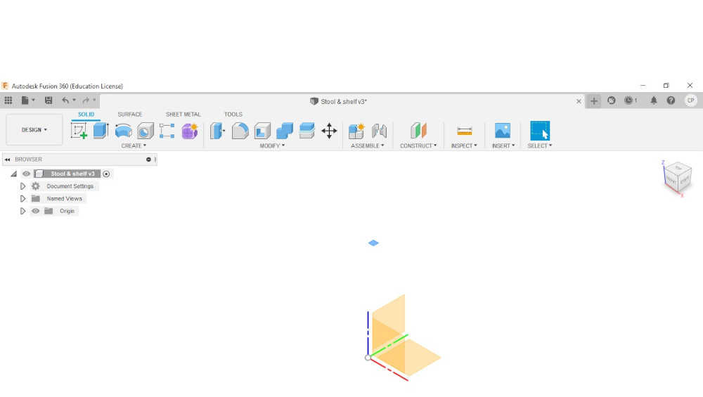
5.Create a circle. On the new construction plane a circle was drawn at the radius of set-in parameters. This circle will be drawn with its center being the origin which will fully constrain it and the sketch can be finished sketch. The sketch can then be extruded to the negative value of the mdf parameter so that the extrusion occurs in the right direction.

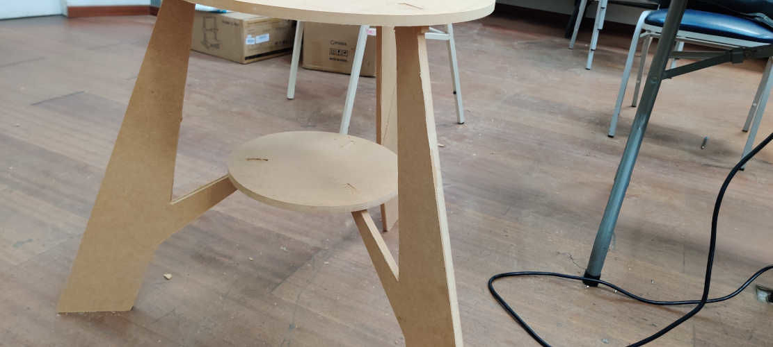
6.Another top-level component was created and renamed as shelf. This was to ensure that when changes had to be made later it would only affect the specific component.
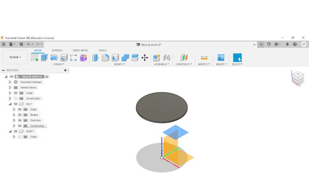
7.An offset plane was created to place the new shelf component in the correct position which would be the height parameter divided by two.
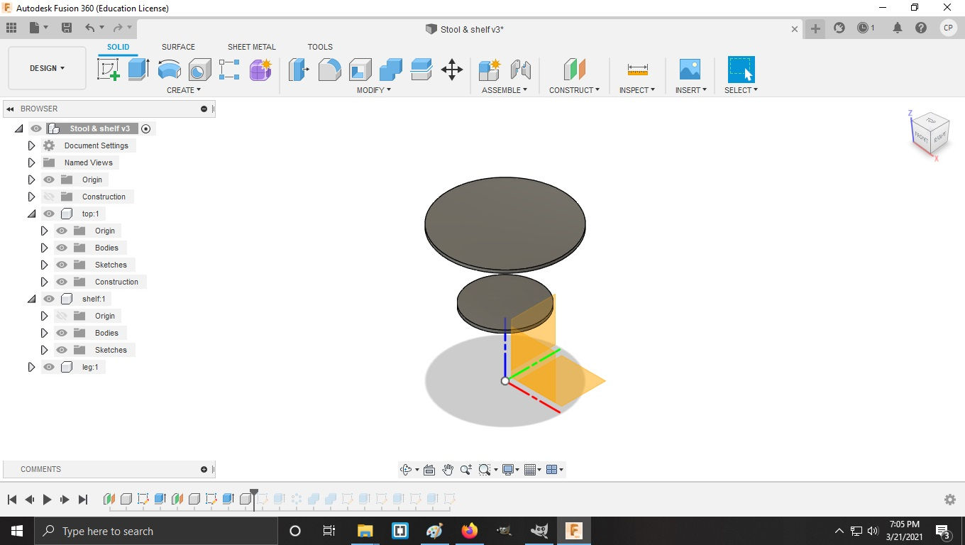
8.A circle was then created on this plane with the origin as its center to ensure consistency throughout the design. This was also extruded to negative the mdf parameter to ensure the extrusion was in the correct direction.
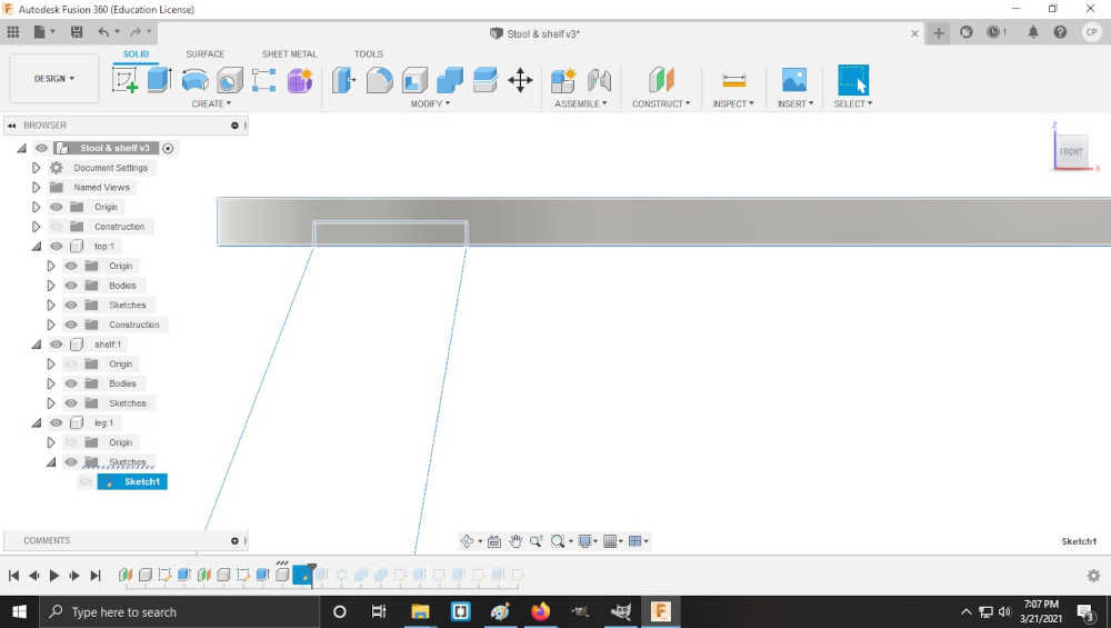
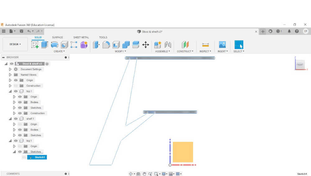
9.At this point another top-level component was created which was renamed leg. The sketch for this component was drawn on the wall plane (any plane other than the top and bottom).
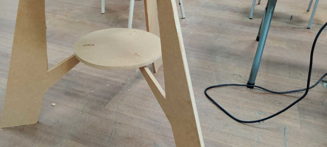
10.Then some rectangular slots were drawn in the top and shelf component. These would be used to attach the legs. The slots were created with a width of the mdf parameter and 45mm length for the top body & 30 mm for the shelf body. The slots on both bodies were constrained to a distance of the mdf parameter from the right edge of the top and shelf body. Also, 4 circles were added to the corner of the slots to transform the slots into a dog bone slot.
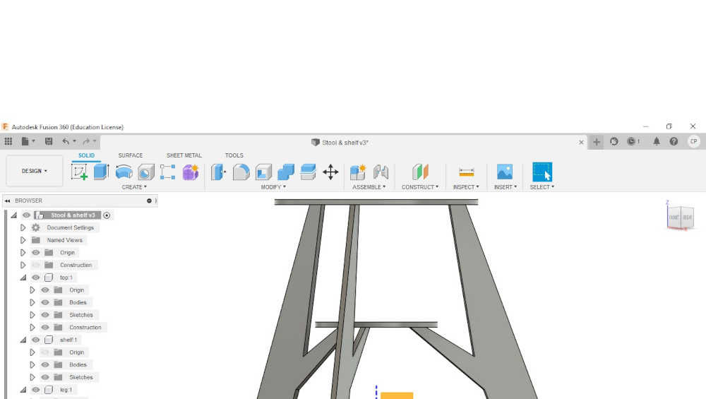
11.At this point I drew the legs using the line command while using the bottom end points of the slots as a reference point. Constraints were also added to ensure that bodies were placed in the right position. After the leg is completed, a circular pattern was used to create the required quantity of legs. This was only possible because the other bodies used the origin as their center point.
12.Now I performed a subtraction to cut the slots into the top and shelf bodies while keeping the legs that created them. This was achieved by selecting the combine tool, choosing the target body (top & shelf) and the tool body (leg). Remember to keep the tool body.
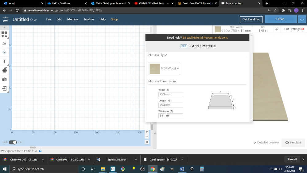
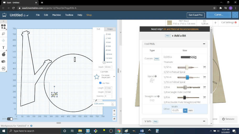
13.Open Easel and select a new project. This will create a blank page where the svg image can be placed to create your design.You can also set the material type ,dimensions and thickness.
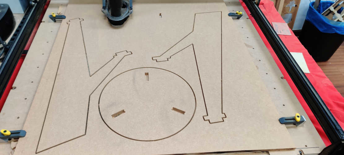
14.Import svg file into Easel.The image will be place at the bottom of both windows. The first window will show the image that will be cut while the second window will show the image and the material in a 3D form. The image can be scaled to whatever size you may require.The type of cut path can be selected at this point and the depth of the cut. Also , the tabs can be added which will secure the part will the router is removing material
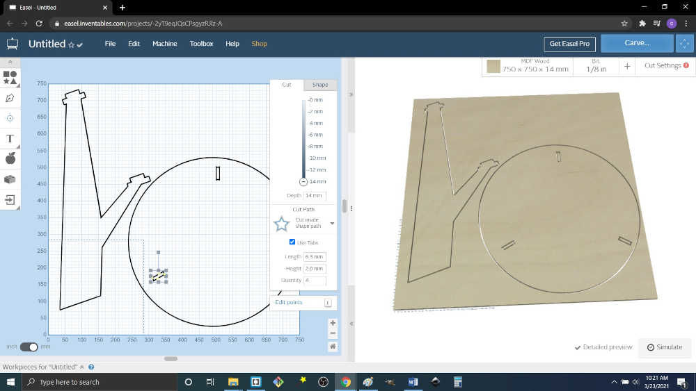
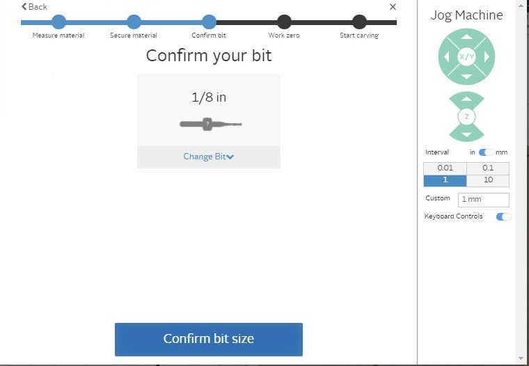
15.Next we selected the bit size. This was determined by the type of bit we had available. In our case we chose a 1/8 inch.The bit size is important as it indicates how much material will be removed.
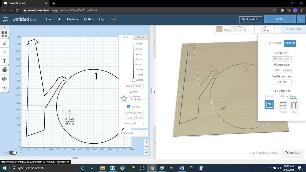
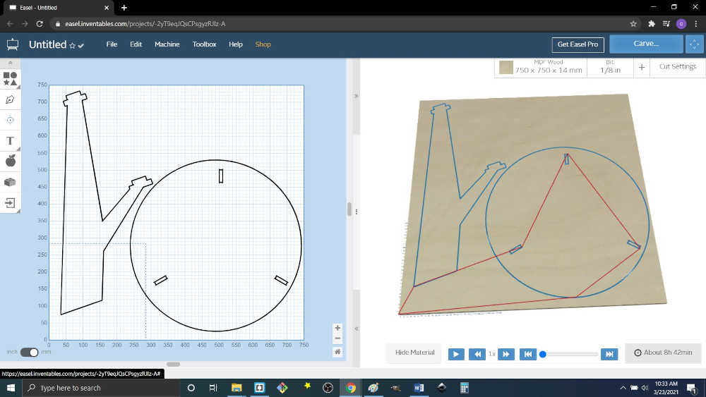
16.We then selected cut settings which is found on the top right-hand corner of the window. This adjusts 4 main settings, feed rate (254mm/min), plunge rate (228.6 mm/min), depth per pass(.4mm) and fill method (offset). If you press on the simulate button it will show how much time it would take to complete the entire job. It is at this point that changes can be made to either increase or decrease the time taken.
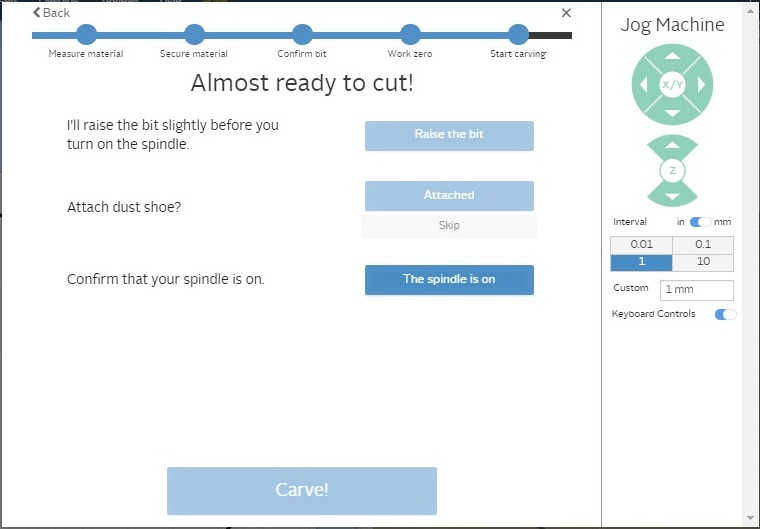
17.The router head was then moved into position. This can be done in two ways , either using the jog machine setting in the easel program or using the directional arrows on the keyboard. The keys will move the router in one of 4 directions, North/Up, South/Down, East/Right or West/Left. While holding the shift key and Up arrow will move the router up on the Z axis or shift key and down arrow will move the router down on the z axis. One point of caution would be to not long press on any of the directional arrow keys when using the machine. This can result in a crash or use of the emergency stop as the keyboard would keep a cache of the keyboard strokes.
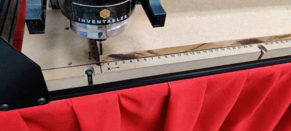
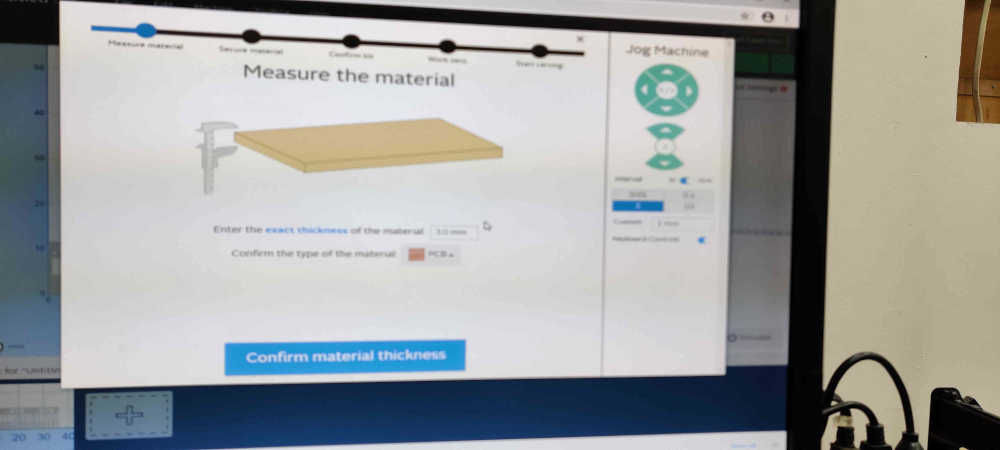
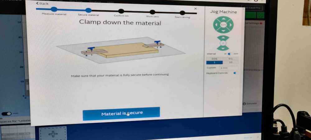
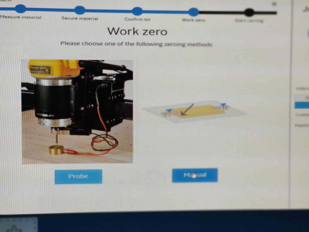
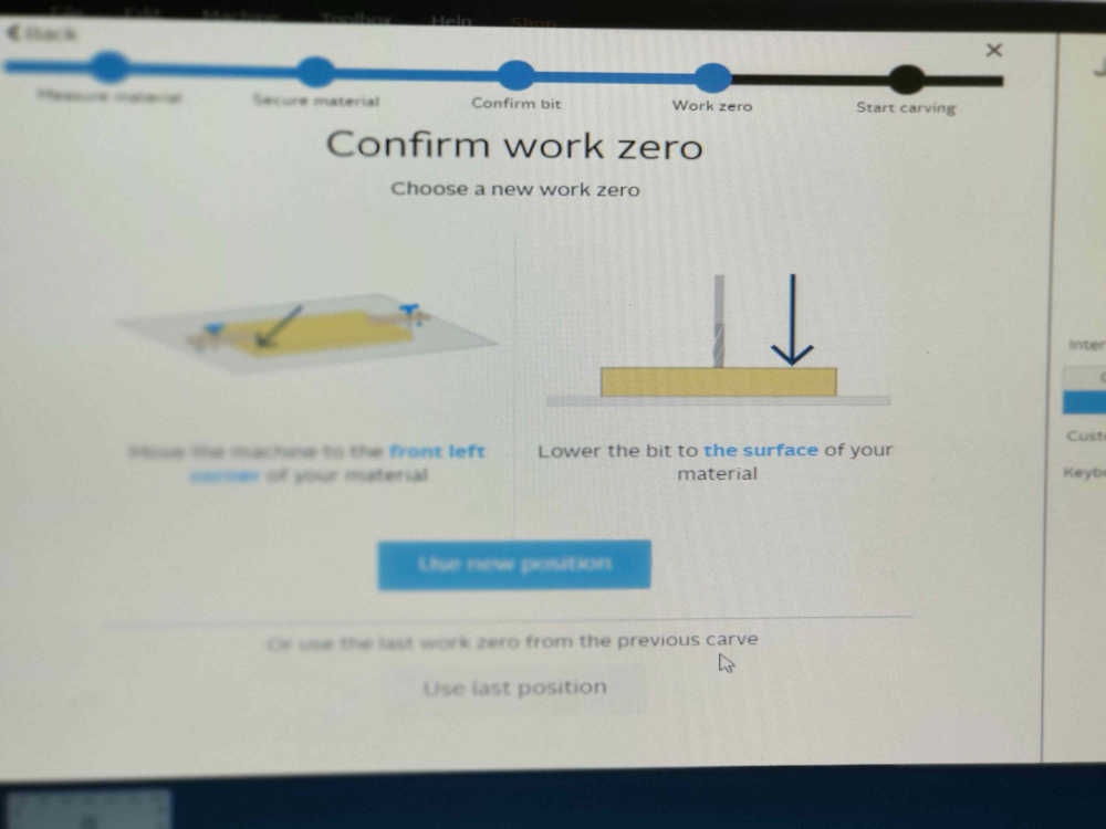
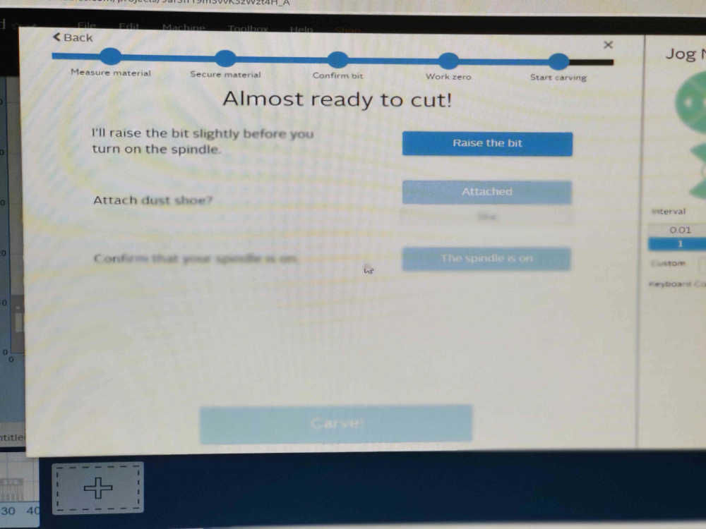
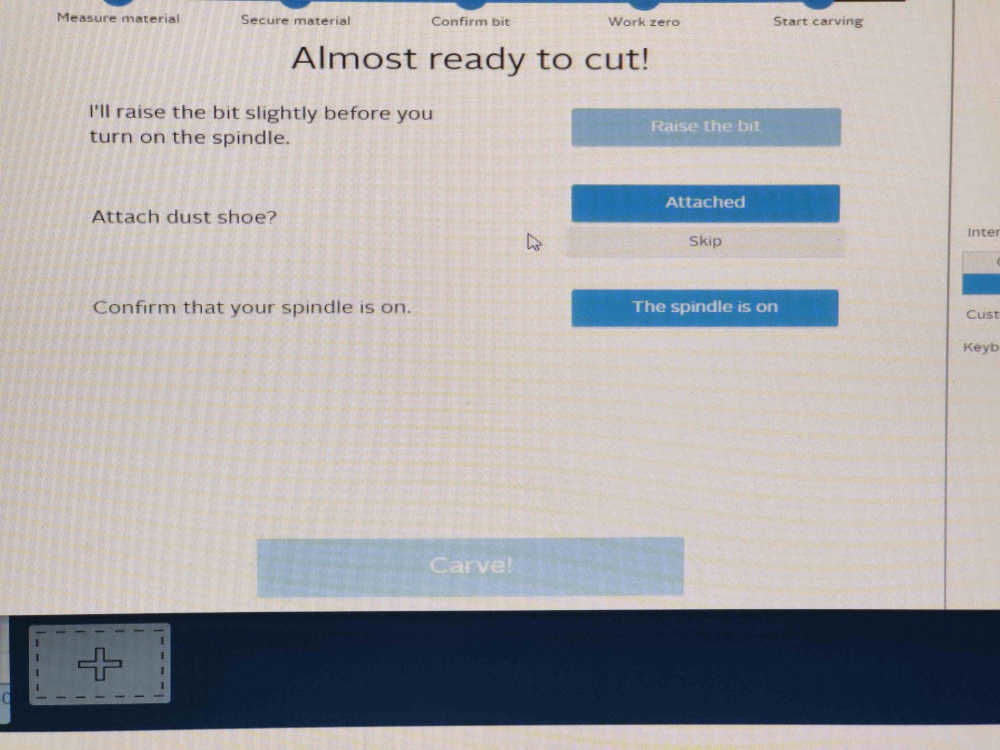
18.When all the requirements have been met, carve can be selected and the program will take you through the final steps of creating the design.This starts from measuring the thickness of the material being used.Also note that this step can be performed prior to point.Then fixing the material to the bed of the machine a waste board was not used as we were not cutting to the bottom of the material.Also not that this step can be performed prior to this step.Then comes the final chance to confirm the bit being used.Then moving the bit to the zero point on the material.Also note that this step can be performed prior to this step.Then the bit will be raised slightly before turning on the spindle. This will prevent any unnecessary contact with the material.Then turning on the spindle and confirming it is on.
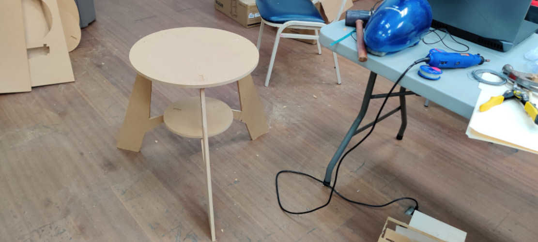
19.At this point the router is stopped and the head moved so that the milled parts can be removed and assembled.
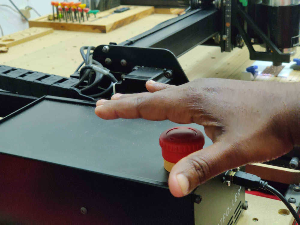
20.Lastly the most import thing to remember when using a CNC router the emeergency stop/ estop is your friend