10. Molding and casting
In this week I looked at the process involved with molding and casting a model I designed. This would include 3-axis milling and documentation of the work done. It was my first opportunity doing this type of activity, so it was a welcome experience. The criteria for this week’s assignment are seen below:
Group assignment:
Review the safety data sheets for each of your molding and casting materials
Make and compare test casts with each of them
Individual assignment:
Design a mold around the stock and tooling that you’ll be using, mill it (rough cut + (at least) three-axis finish cut), and use it to cast parts.
Group Assignment
This week’s group assignment looked at us reviewing a safety data sheet for the materials we would be using. The other members who worked on this assignment are listed below:
James Khan
Marvin Holloway
Nervene Bhagwandass
Ravi Baldeo
Terrence Carew
- Group Project Link
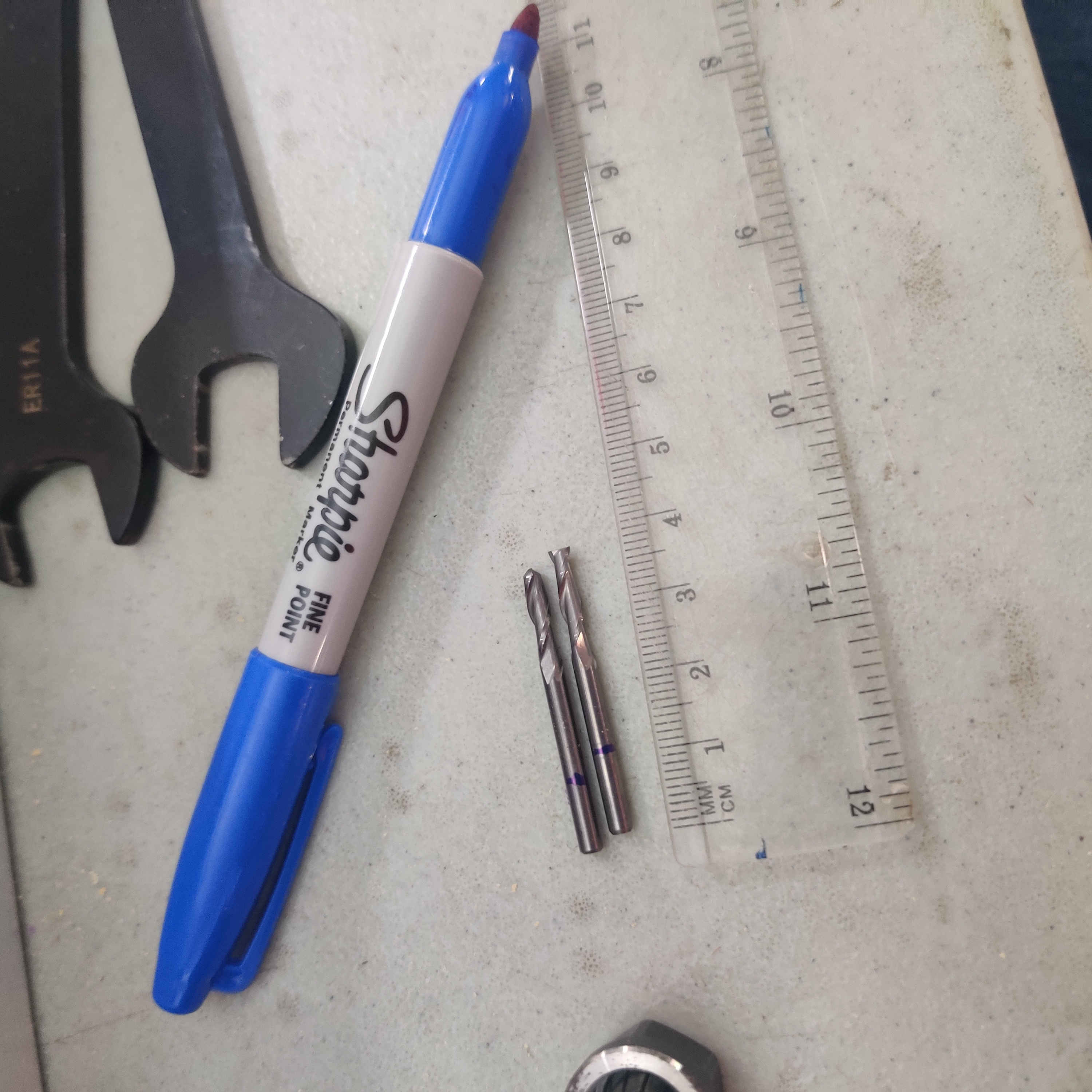
Preparation: Measurements
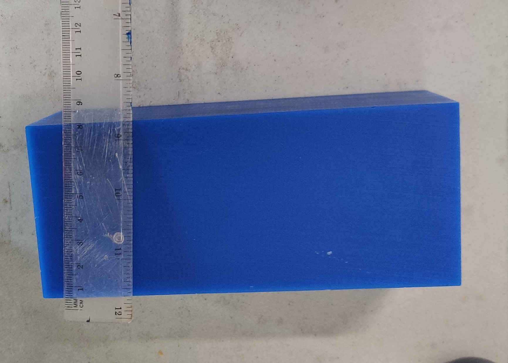
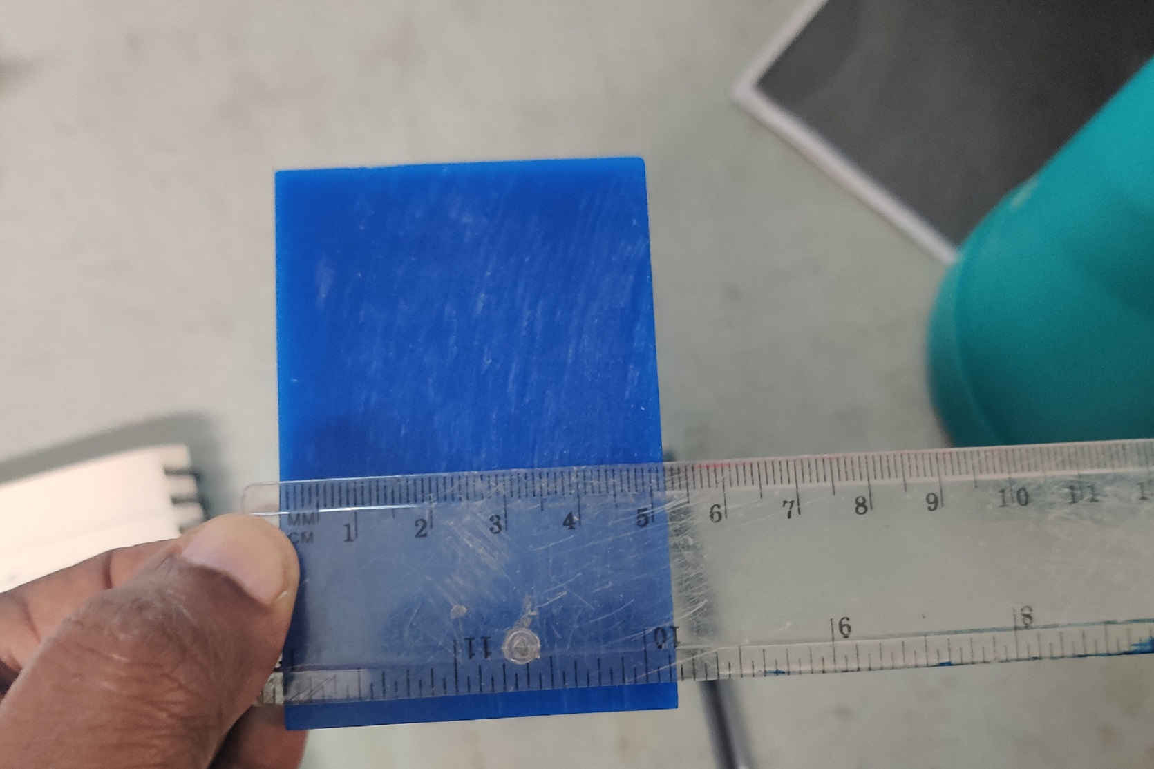
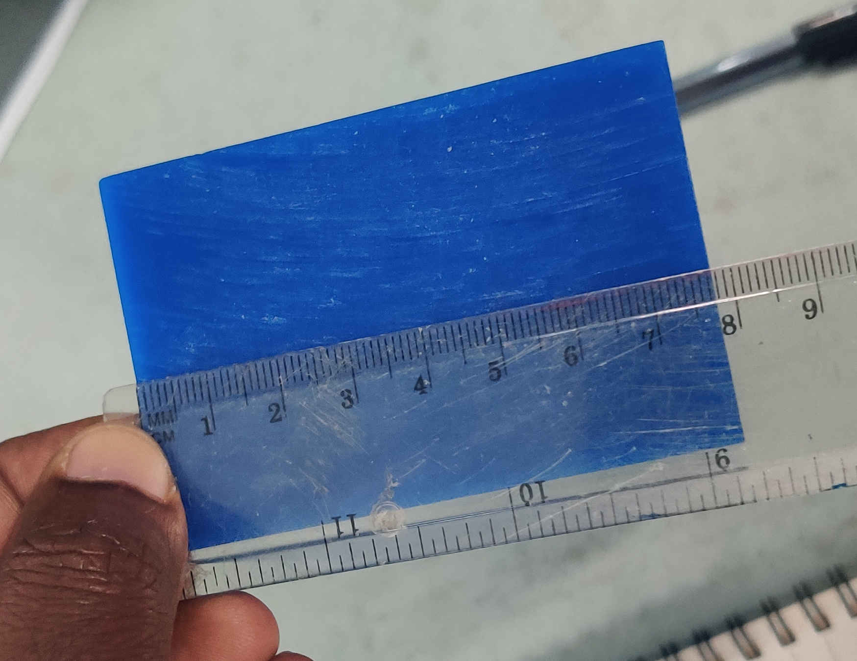
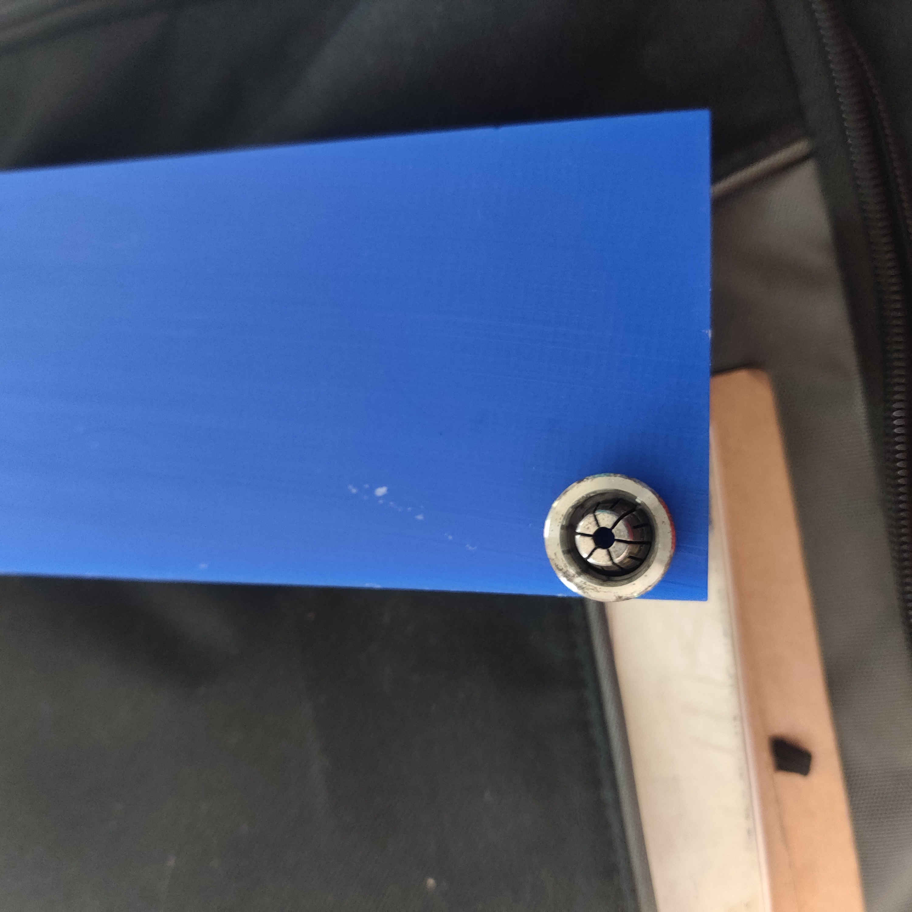
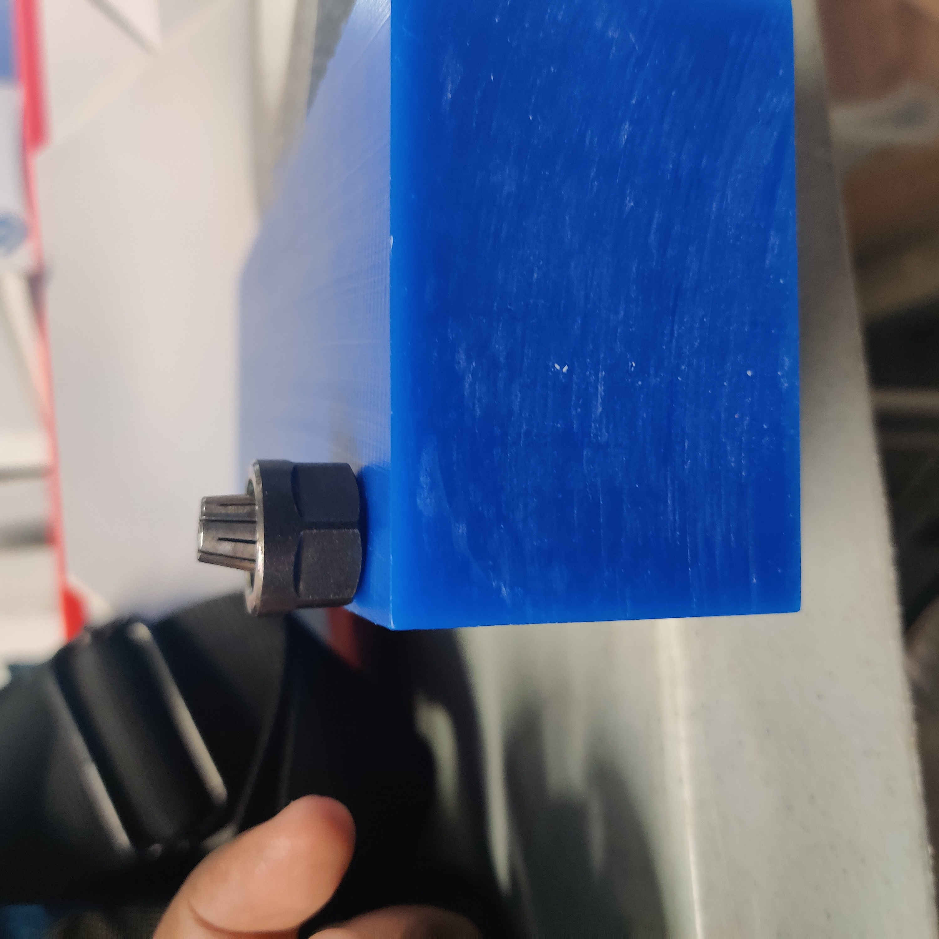
1.Before using Fusion 360 to design my mold out of wax, I took dimensions of the wax block I would be using.
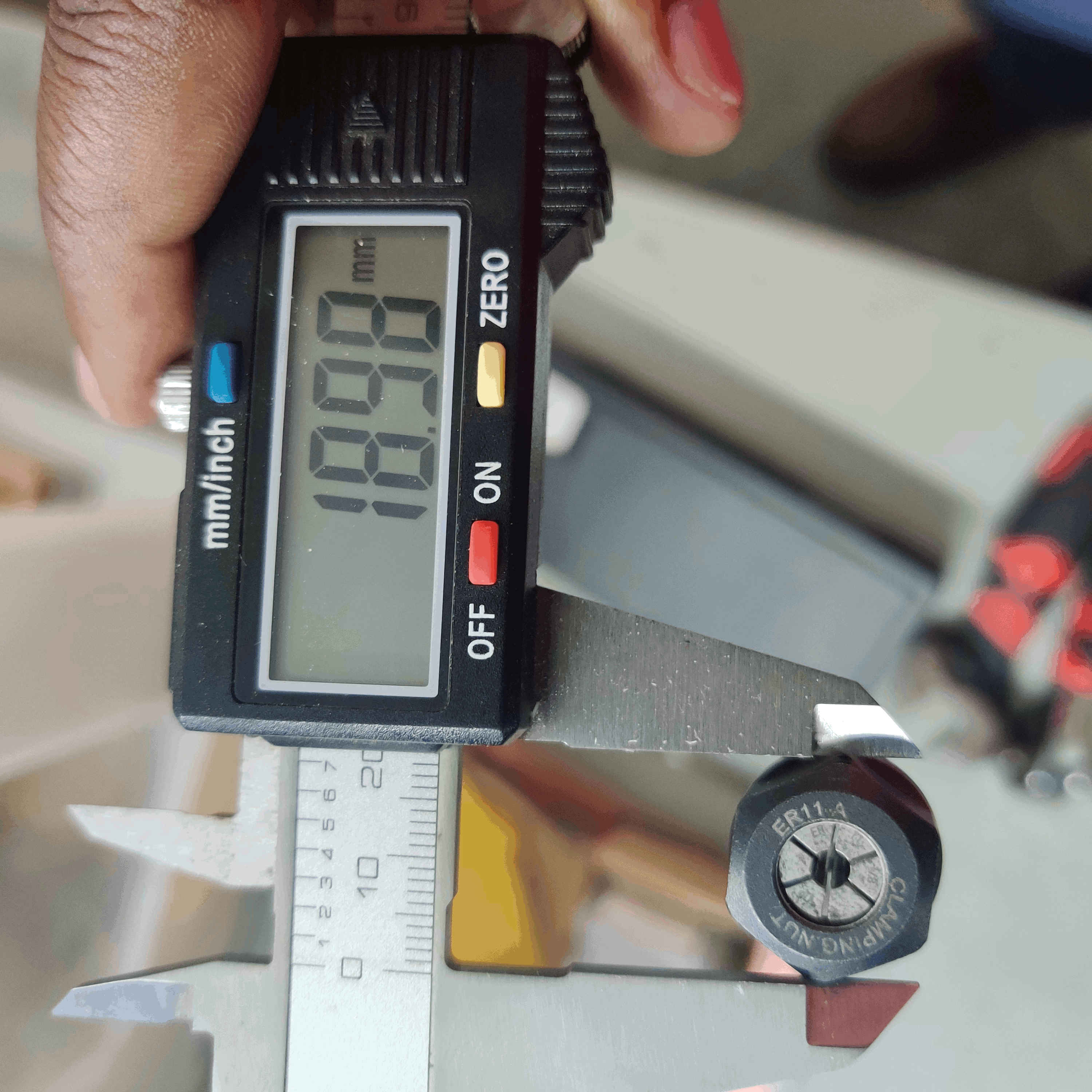
2.Then I took dimensions of the collet for the precision mill I would be using.
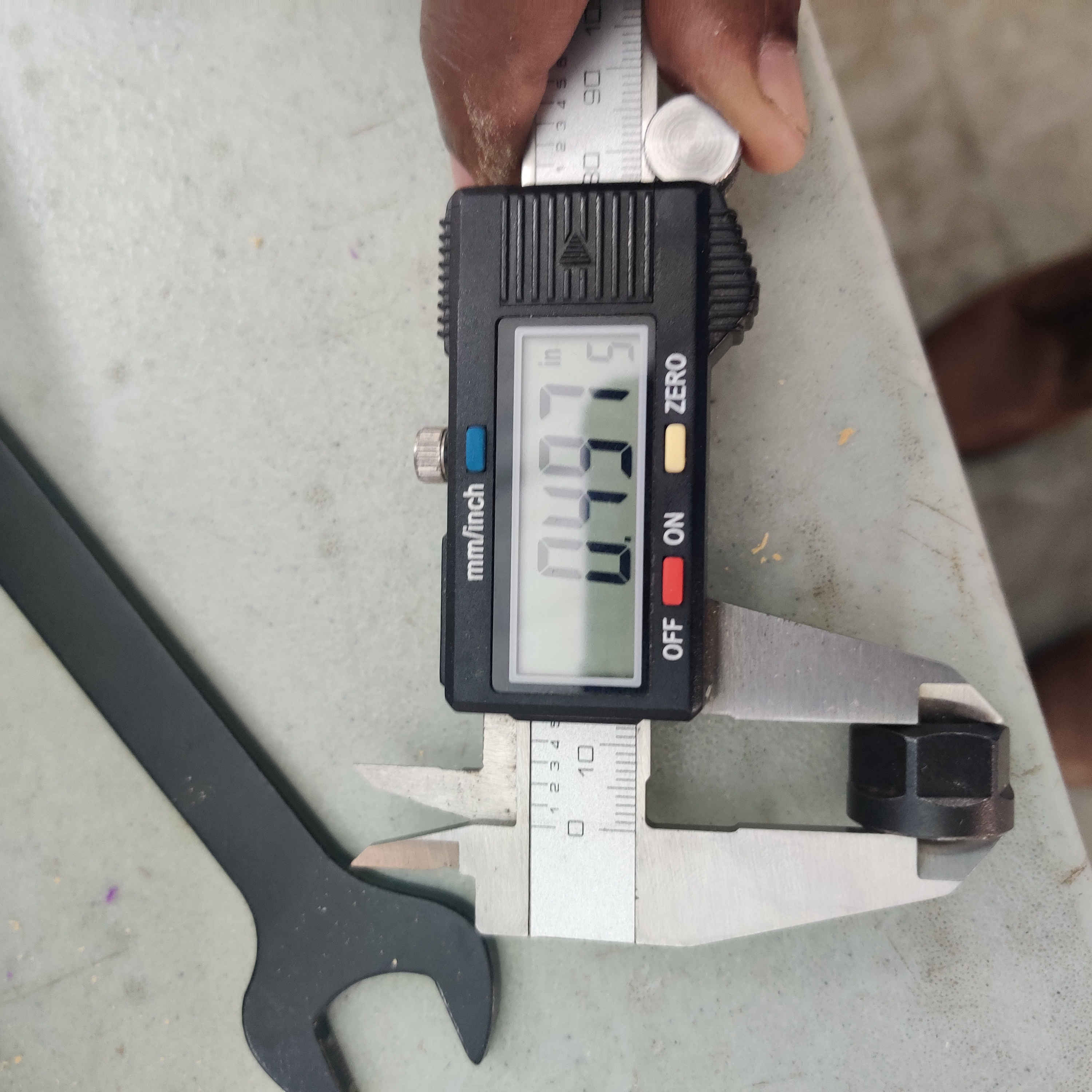
3.Then I looked at both the wax block with the collet to determine the distance I would need collet when machining.
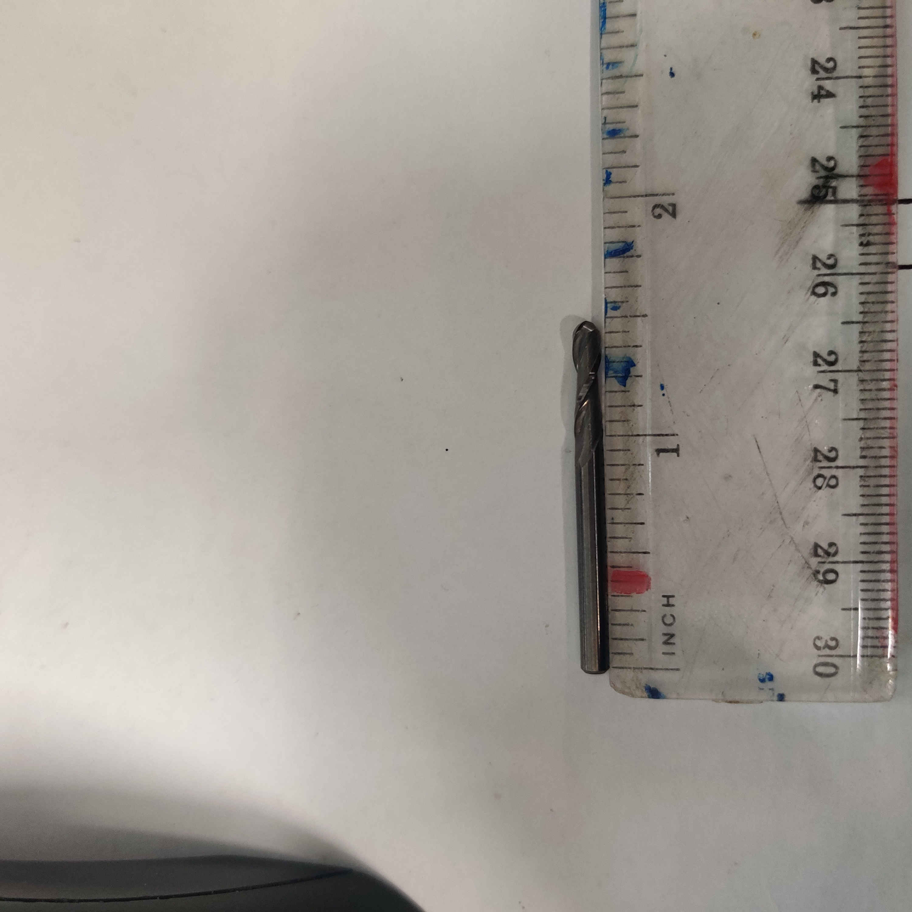
4.Then I took dimensions of the two end mills I would be using.
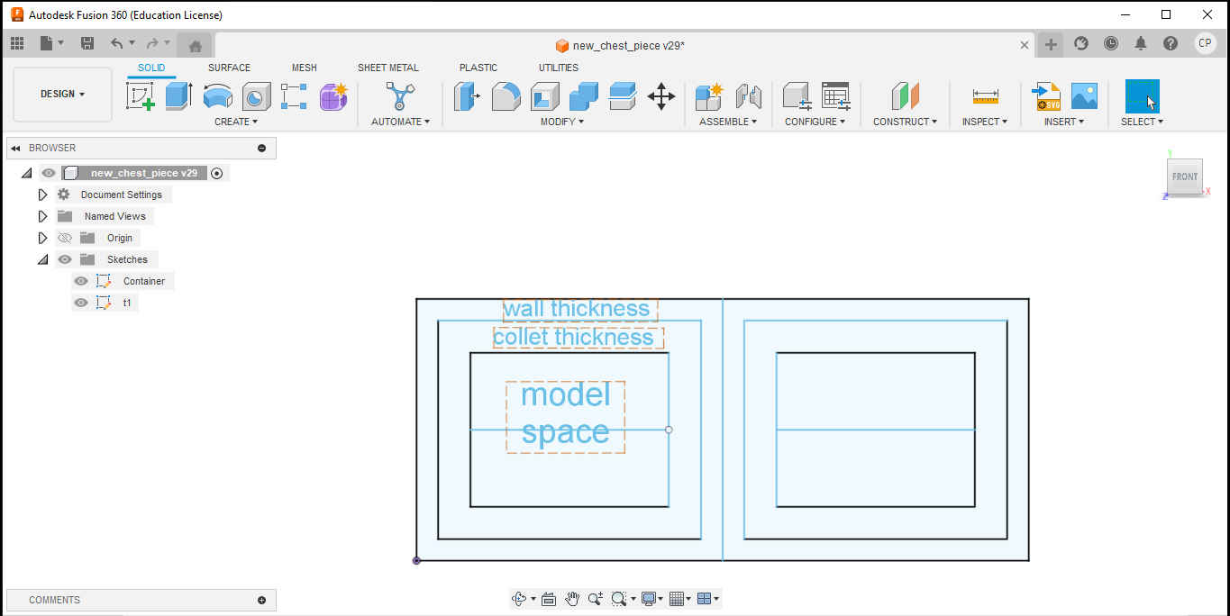
Fusion 360: Design
1.After opening the design workspace in fusion 360 I used the measurements I acquired earlier to create a sketch which took into consideration wall thickness, collet diameter and workable area for my model.
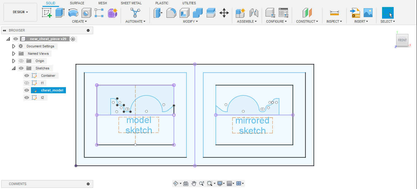
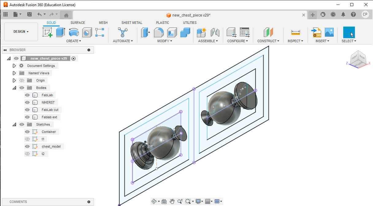
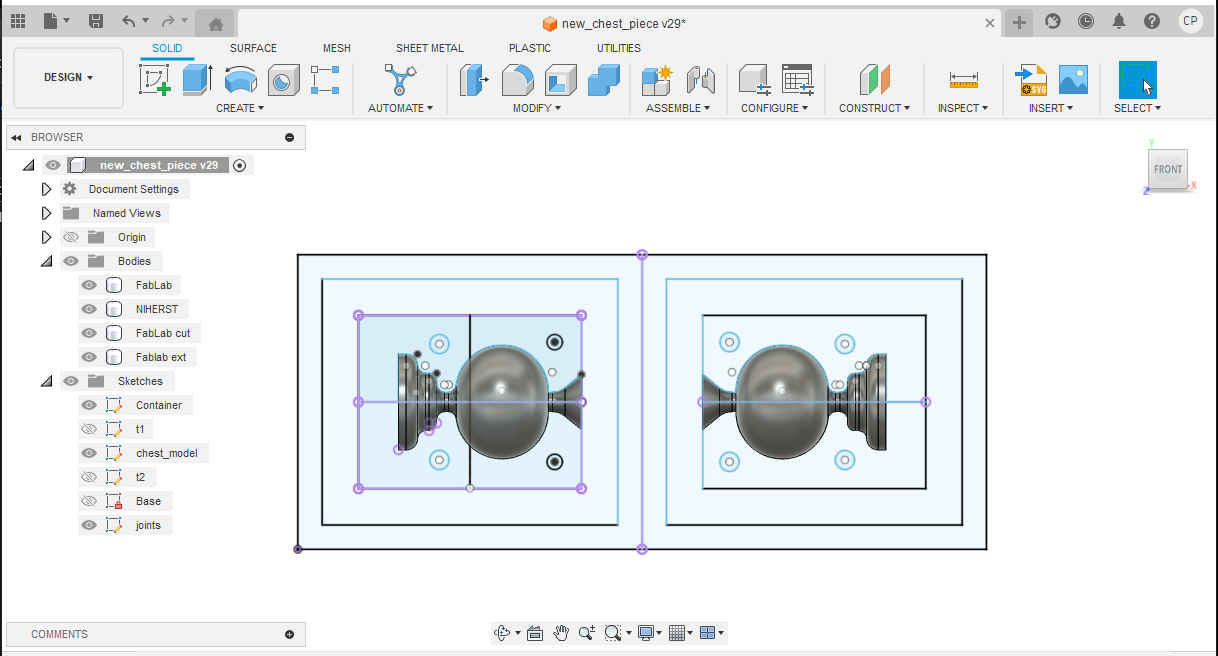
2.Then, I created a 2D sketch of the model on one half of the wax block (model space). After the use of lines placed at various midpoints the model was mirrored into the other model space.
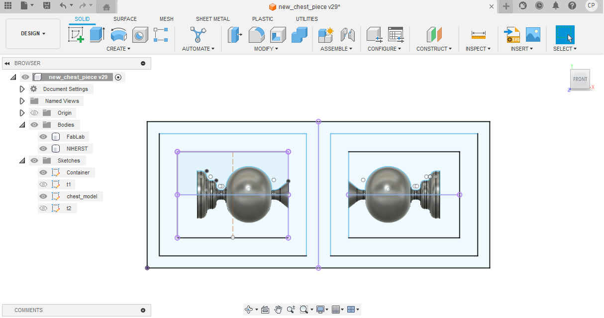
3.Using the revolve command both model sketches were turned into 3D models.
4.Both models were then split in two using the split command.
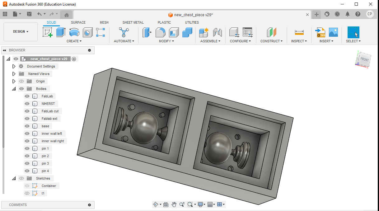
5.Then the places where the joints that would hold both halves of the mold were created.
6.Then the walls, base and step-down were created. Also, one model had pins created while the other had material removed to create the places where the two halves would be held together.
Fusion 360: Manufacturing
1.First, I changed the workspace to manufacture from design.
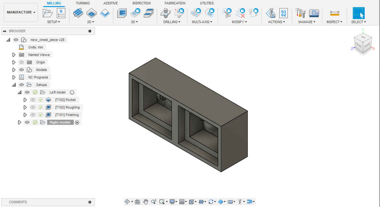
2.Then, I selected setup to prepare the CAD model. Under setup the required operation (milling was chosen. By default, it is set to milling but this can change as required.
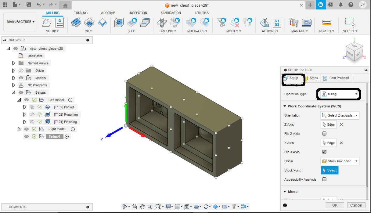
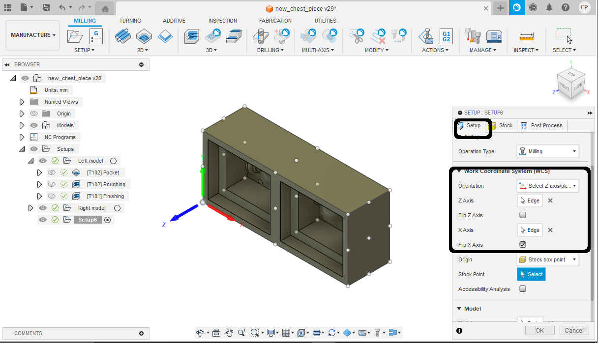
3.Then select orientation to change the WCS to the desired location. I chose select Z and X axis.
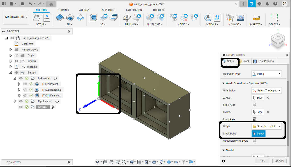
4.Then select the origin or the zero point (0 Z,0 X, 0 Y) of the material. I chose stock box point and top left corner.
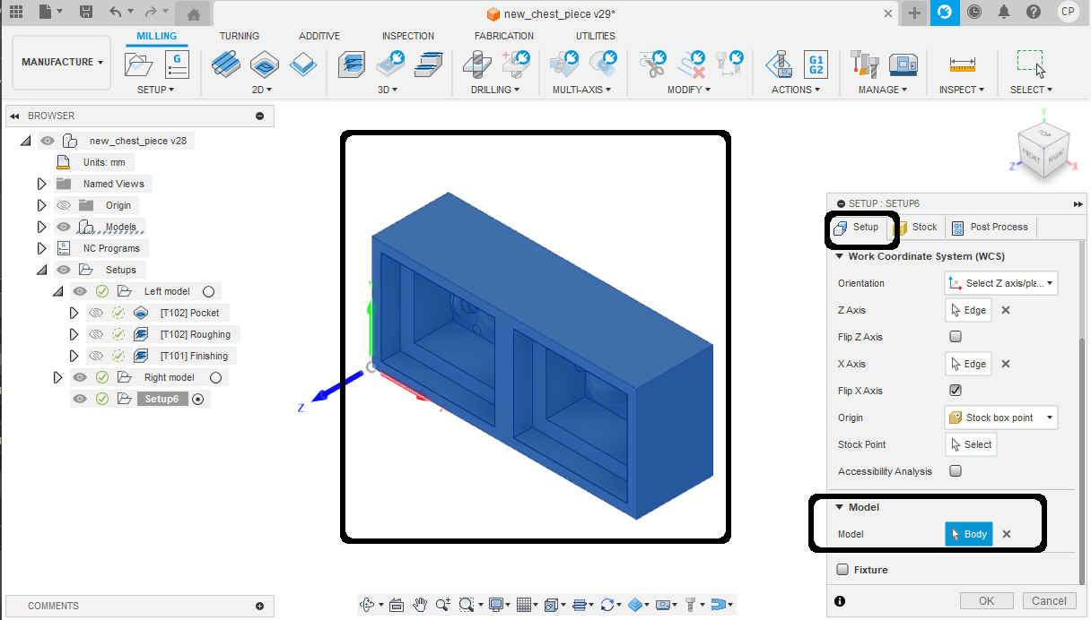
5.The select body so the program knows what it will be milling.
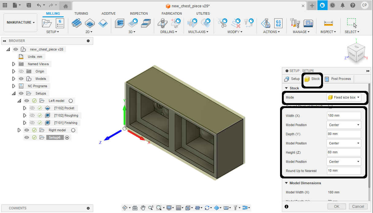
6.The select stock at the top of the pop-up window. I then select fixed stock and use the dimensions I took of the wax block.
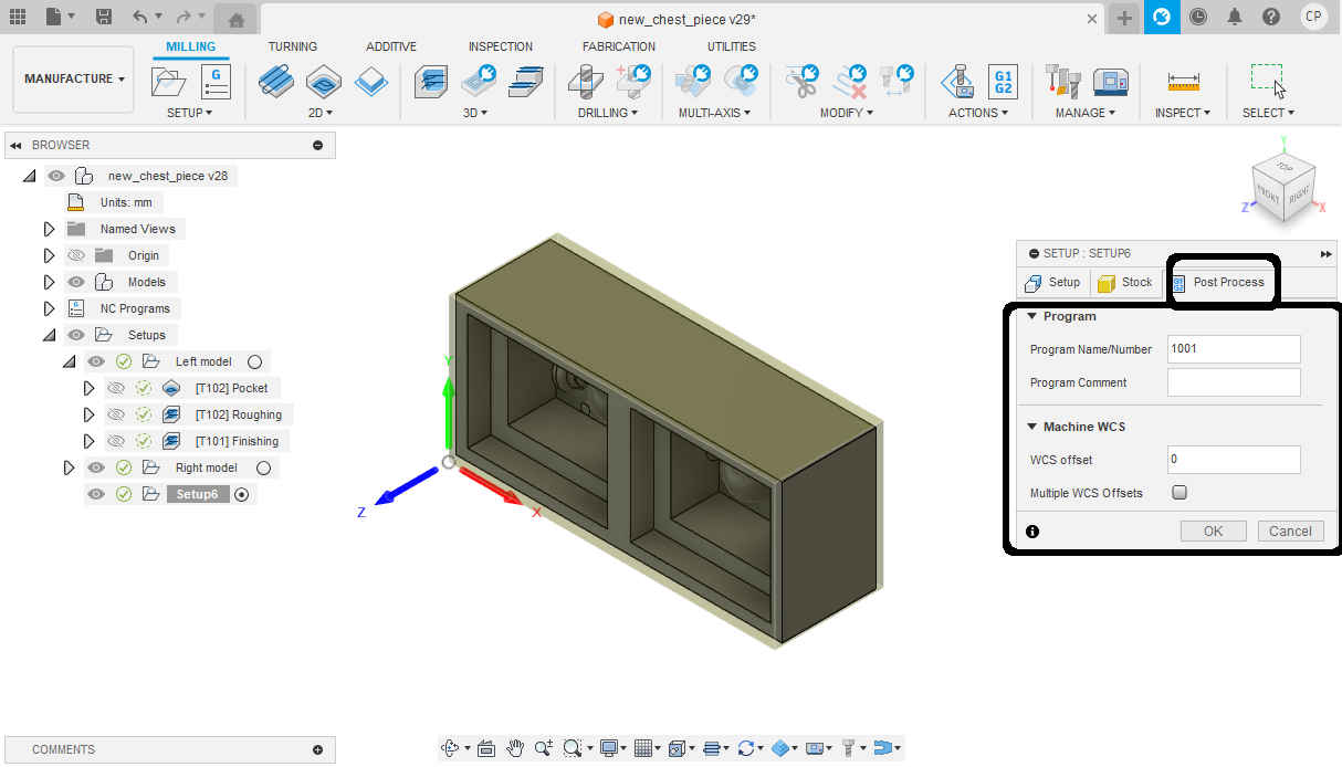
7.No changes were made from the default for post processing.
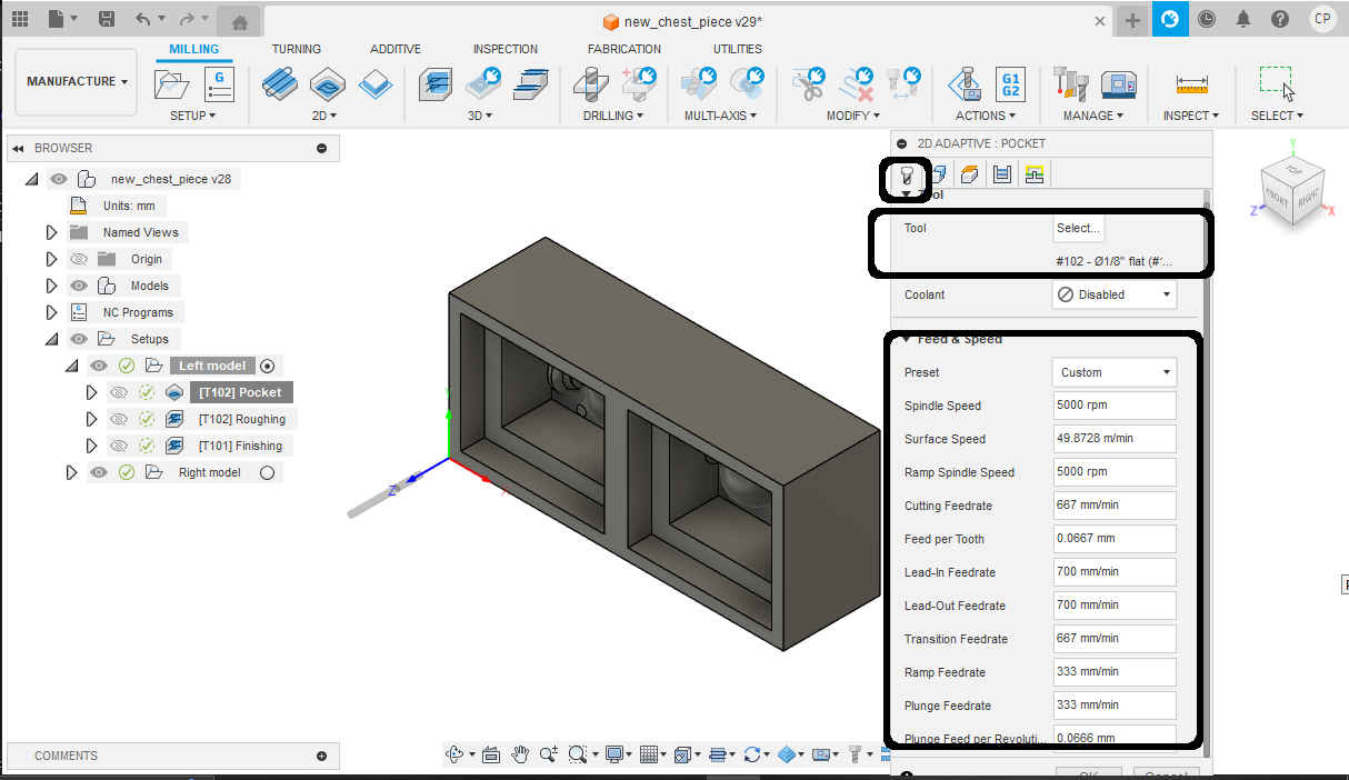
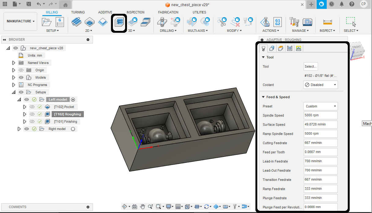
8.Then in 2D tool part I selected “2D Adaptive Clearing” and selected my first endmill for roughing operation Nomad #102 (1/8-inch flat endmill).Ps. I download fusion library for the precision mill (Nomad 3) at the lab.(https://www.youtube.com/watch?v=FA7szUQZ9ZM). Then under “Tool” I selected custom preset as I would change the default setting and used the settings seen in the image based on some recommended setting for the machine in the video.
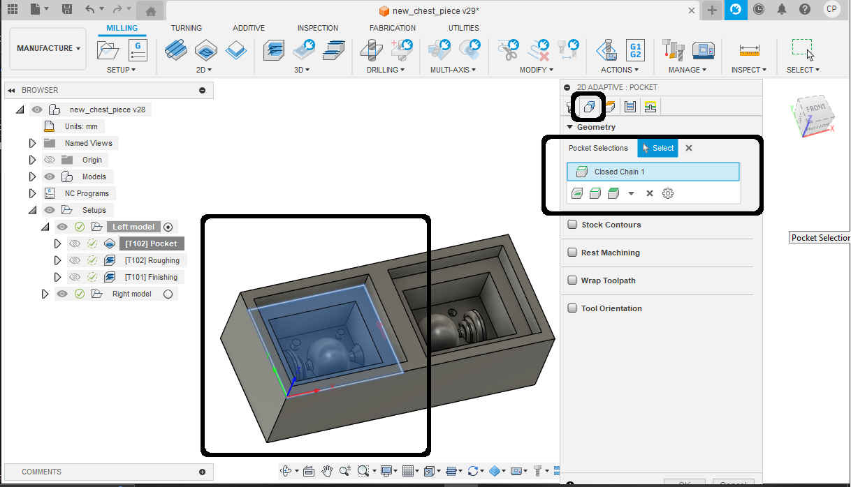
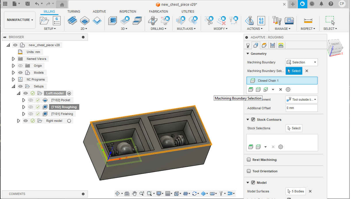
9.Then under “Geometry” I selected the area I wanted to remove.
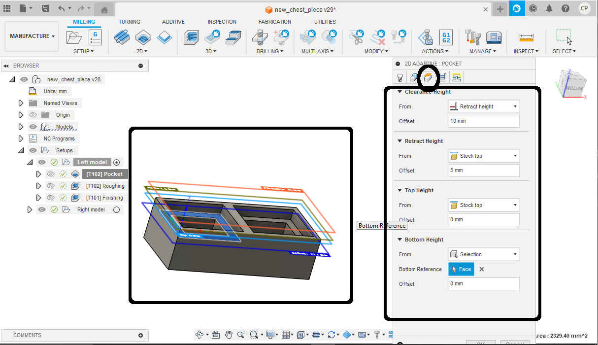
10.Then under “Heights” I left everything as default.
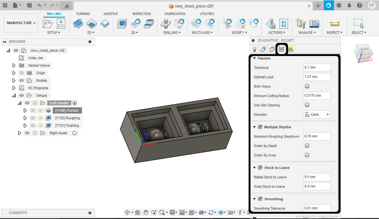
11.Then under “Passes” I changed the optimal load to 20% of the tool diameter. I also selected smoothening to improve quality of cut and reduce code size. Feed optimization was also selected to improve surface finish and tool life.
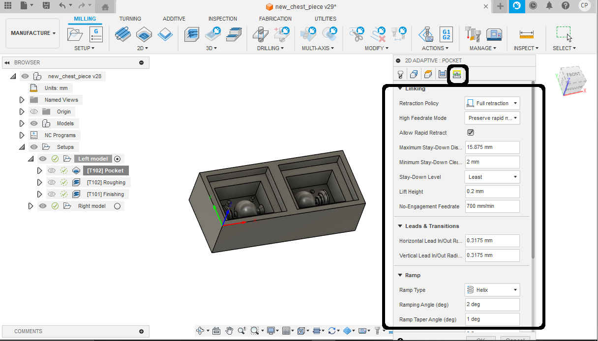
12.Then for “Linking” I left as default settings.
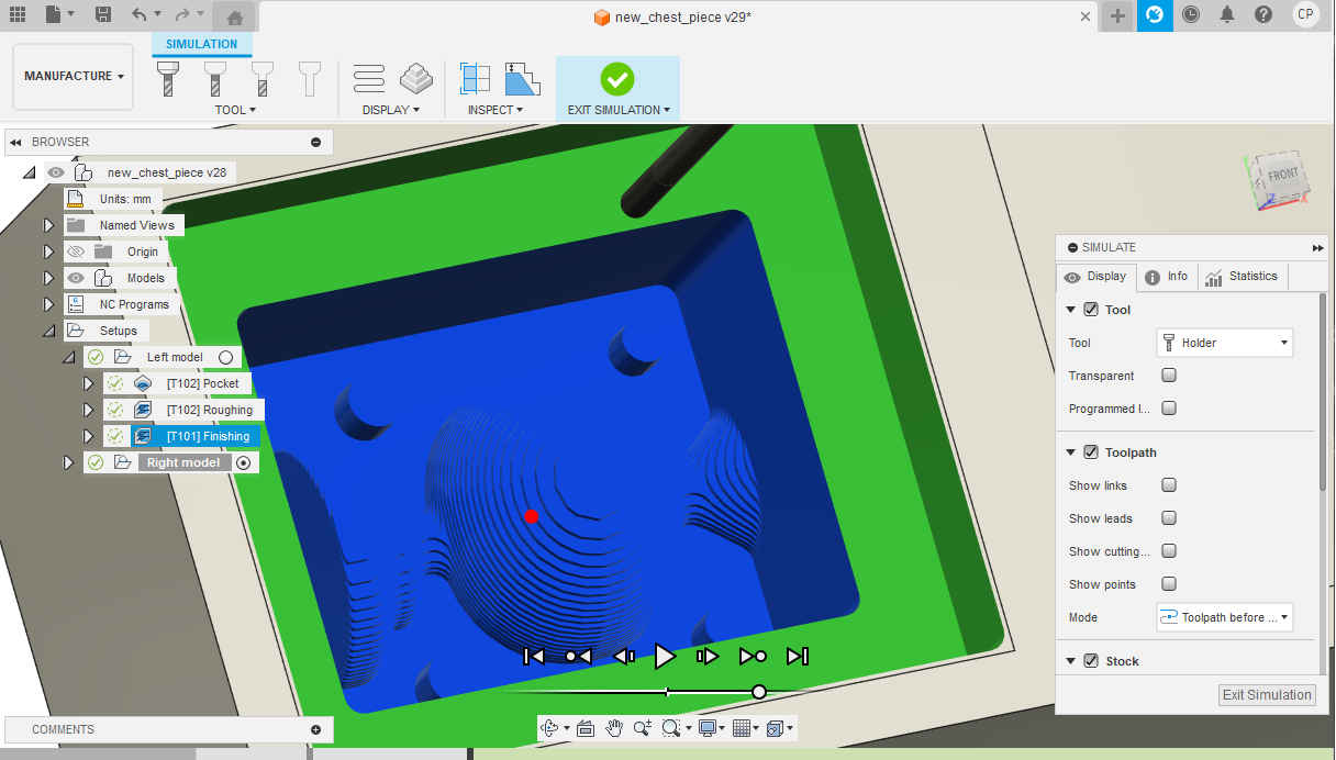
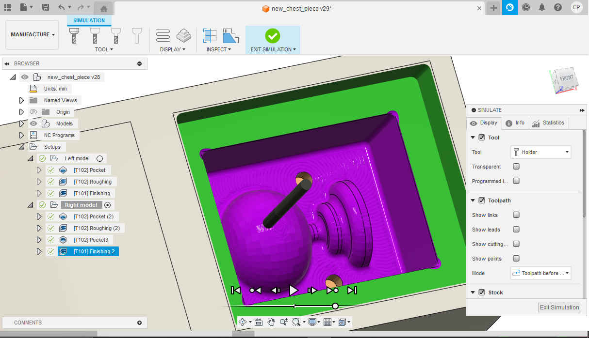
13.Then I selected simulate under the action tab to ensure operation would be performed how I wanted it.
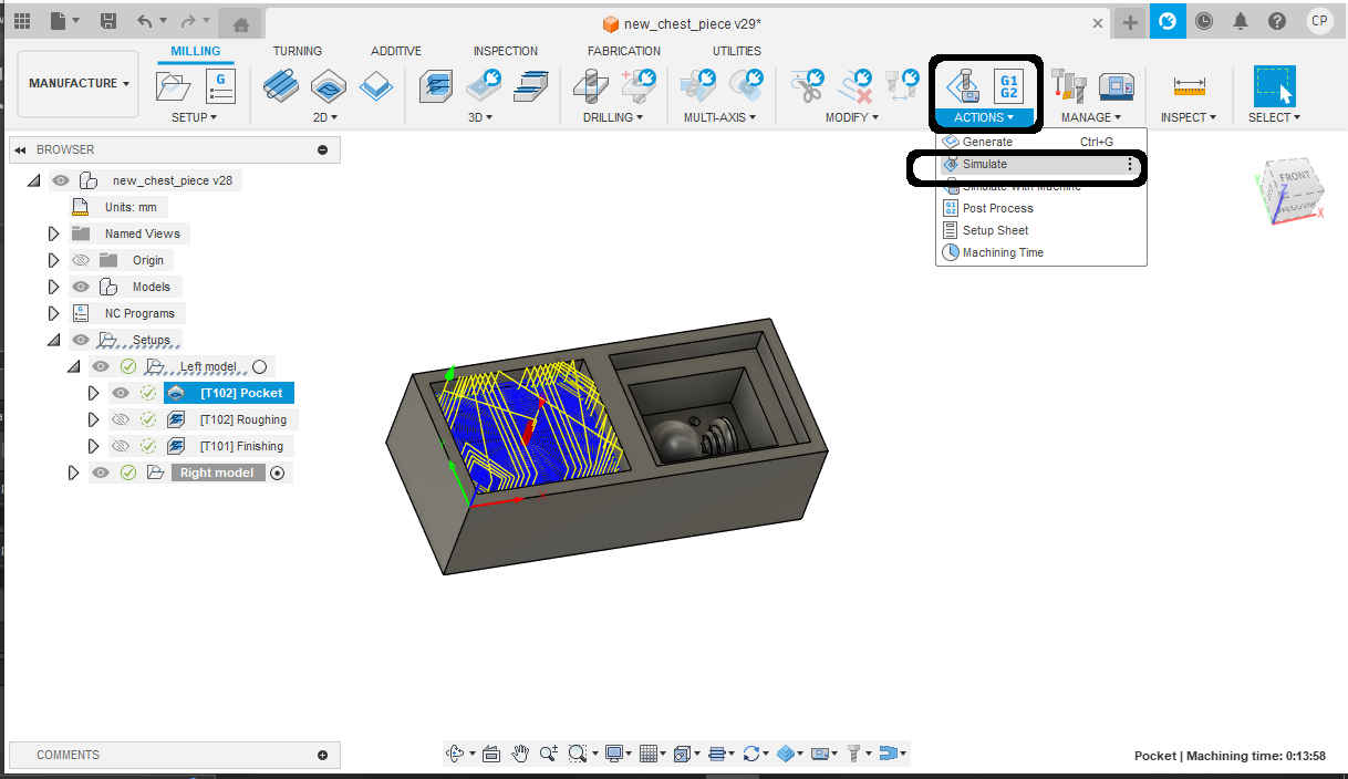
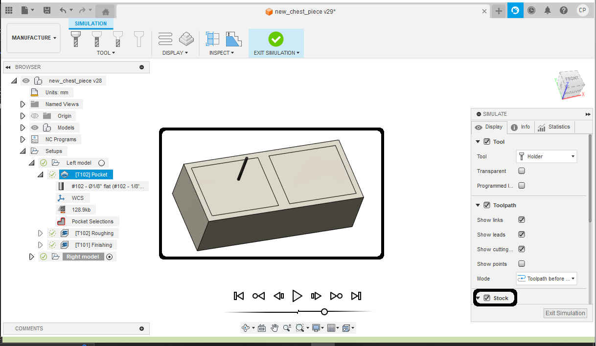
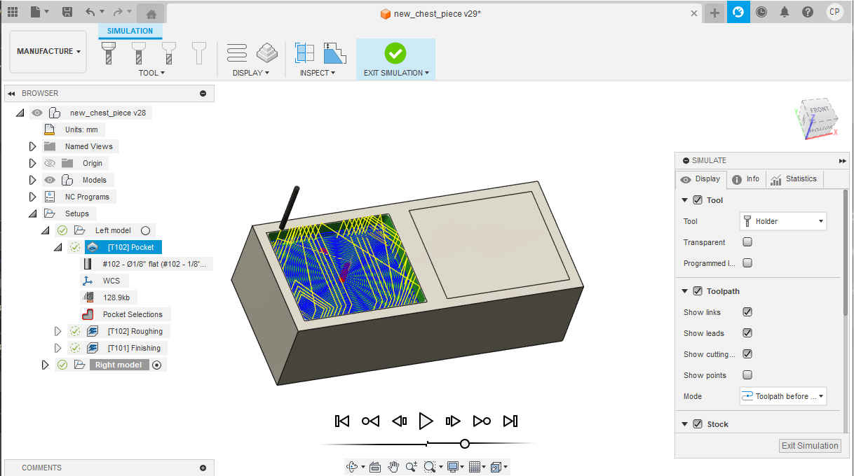
NB. Ensure stock is selected for a better view.
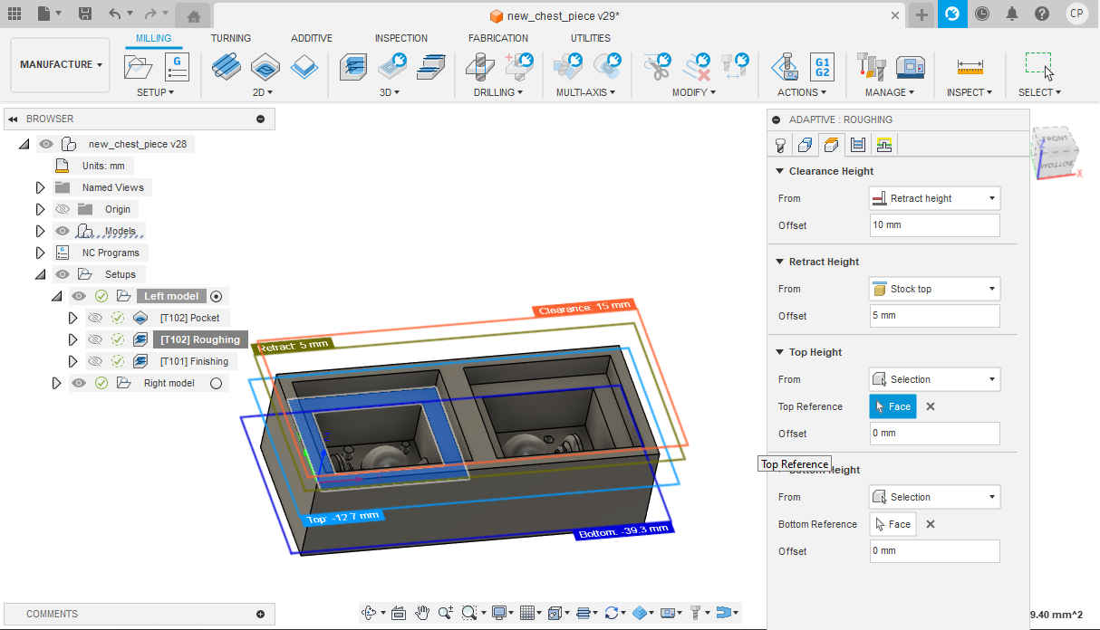
14.Then under 3D I selected adaptive.
15.Then because I was using the same endmill the settings mostly remained the same as with the previous operation. The two changes being under “geometry “to select the new areas to mill and heights indicating the top and bottom boundaries.
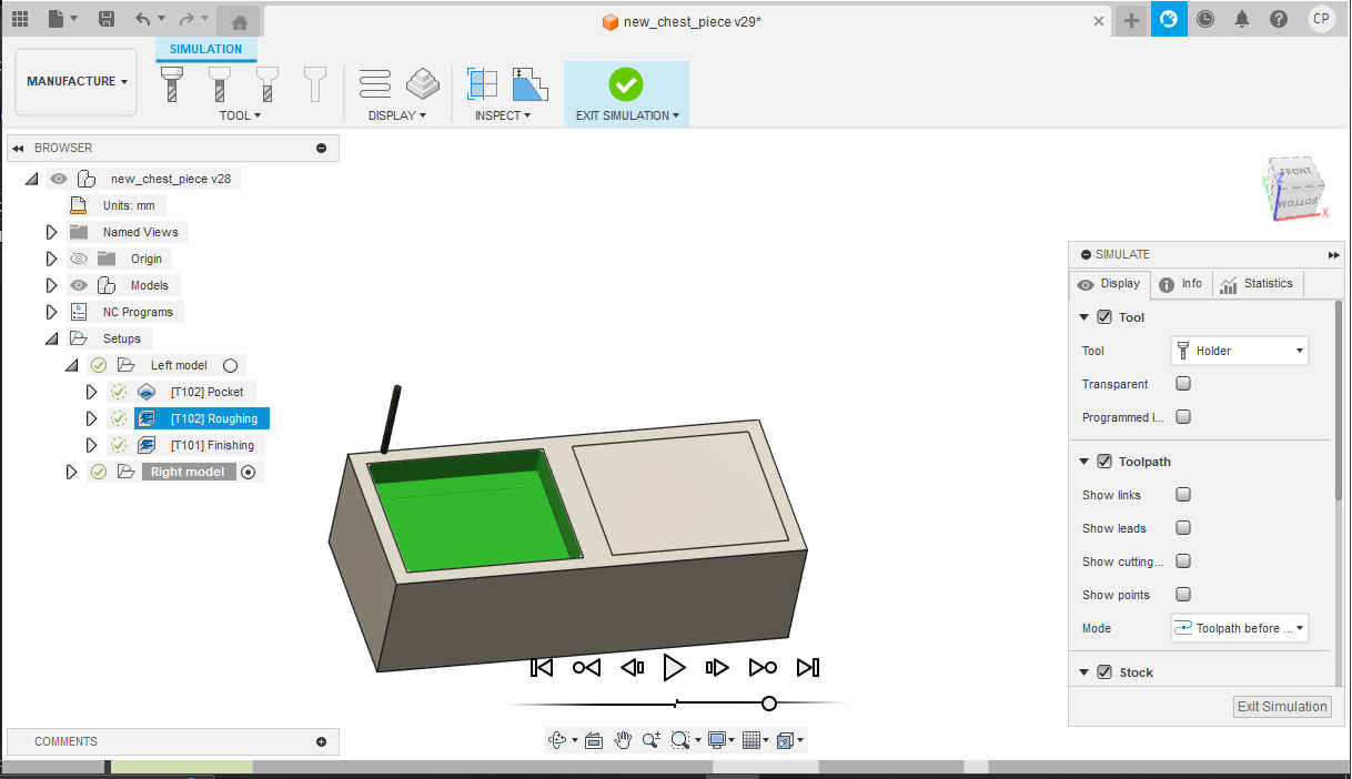
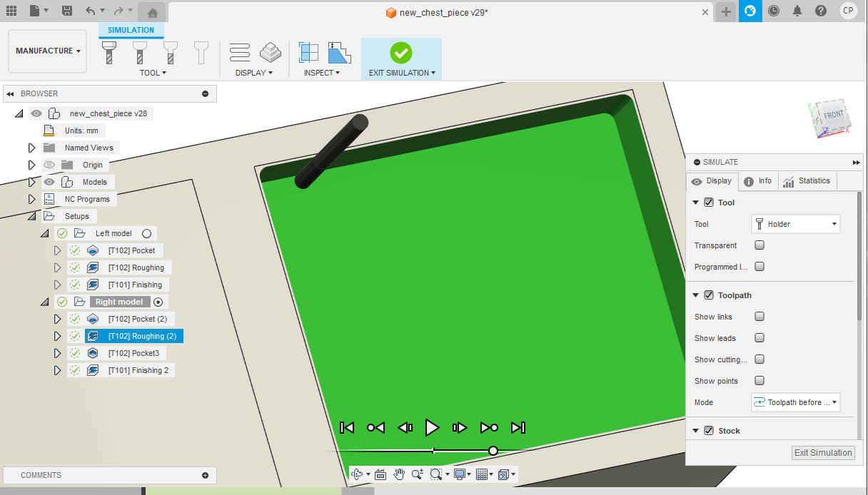
16.Then I selected simulate under the action tab to ensure operation would be performed how I wanted it.
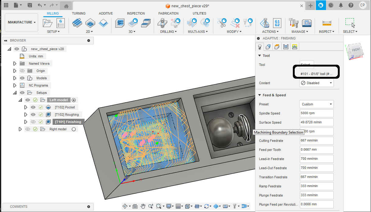
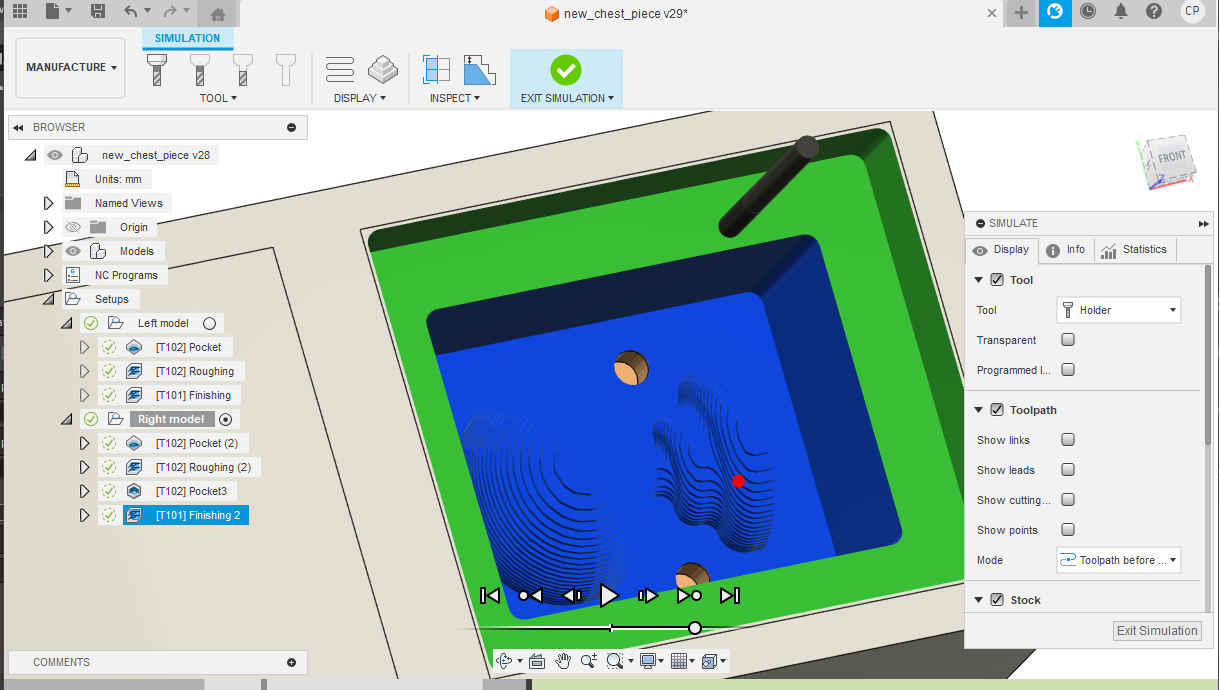
17.Then I copied the toolpath used in step 15. as I was going to perform a finishing pass using the #101 endmill ball nose.
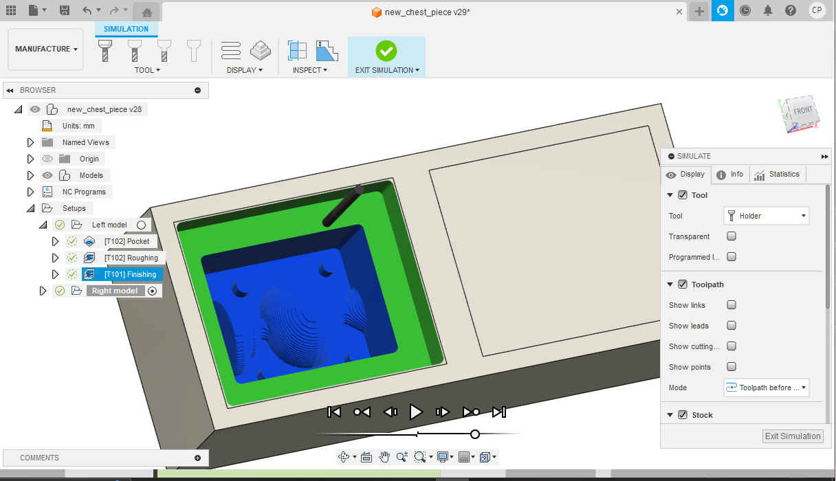
18.Then I selected simulate under the action tab to ensure operation would be performed how I wanted it.
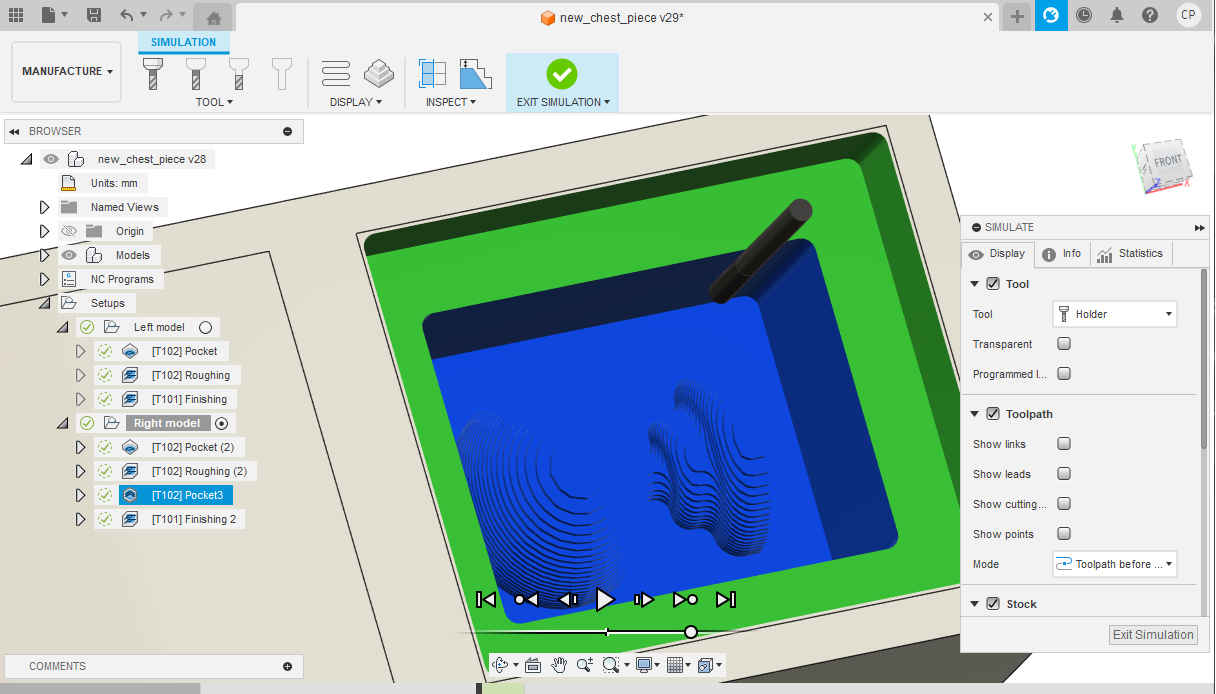
19.Then I repeated step 8-18 on the other half of the wax block to complete the second half of the mold. There was one additional toolpath used to create the pockets for the pins from the other half of the mold.
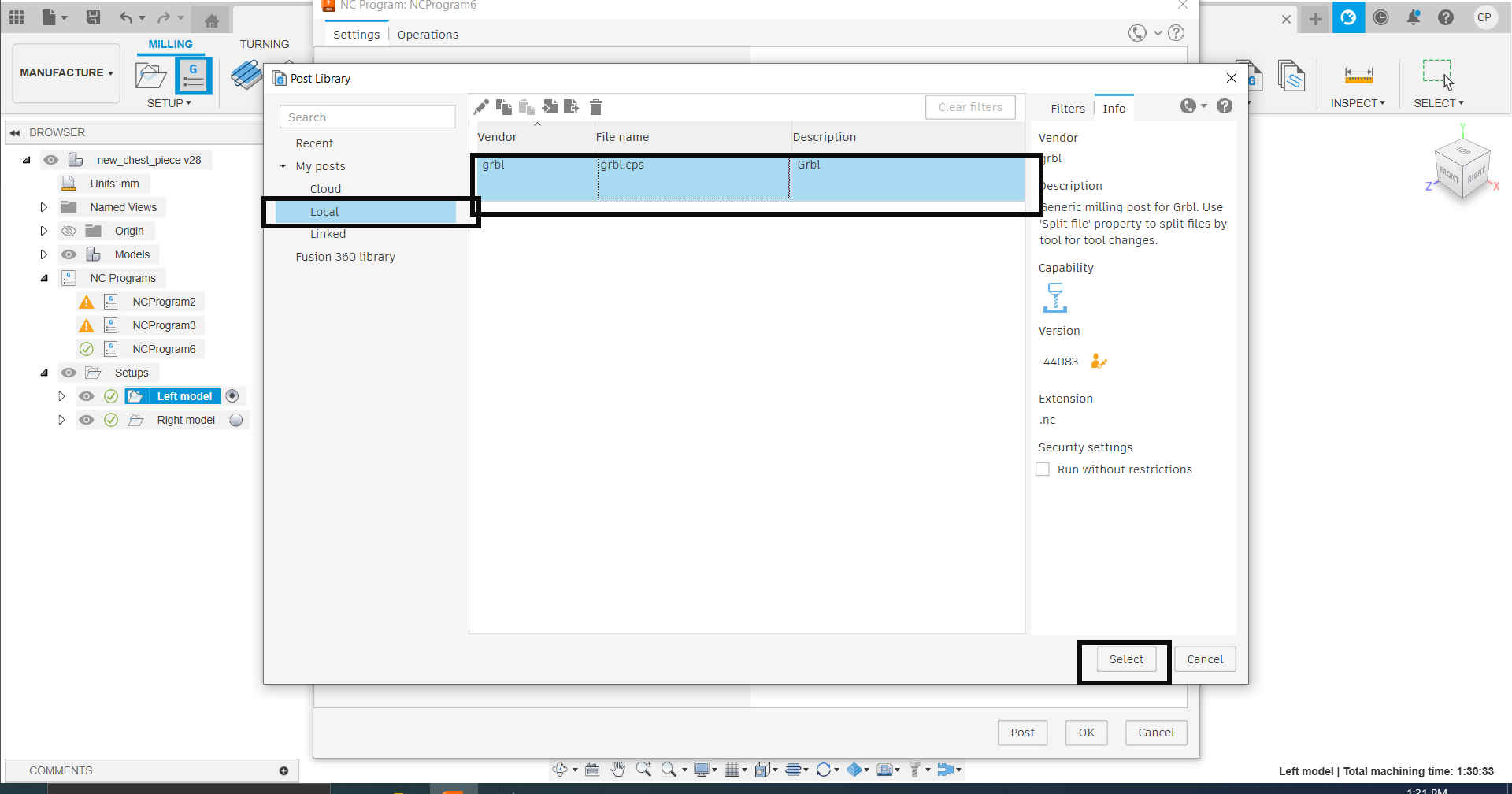
20.Then I downloaded the post processor (grbl) from the Autodesk webpage. After the file was downloaded, I moved the file to the Fusion CAM 360 post folder. The video link shows the steps for adding the post processor.
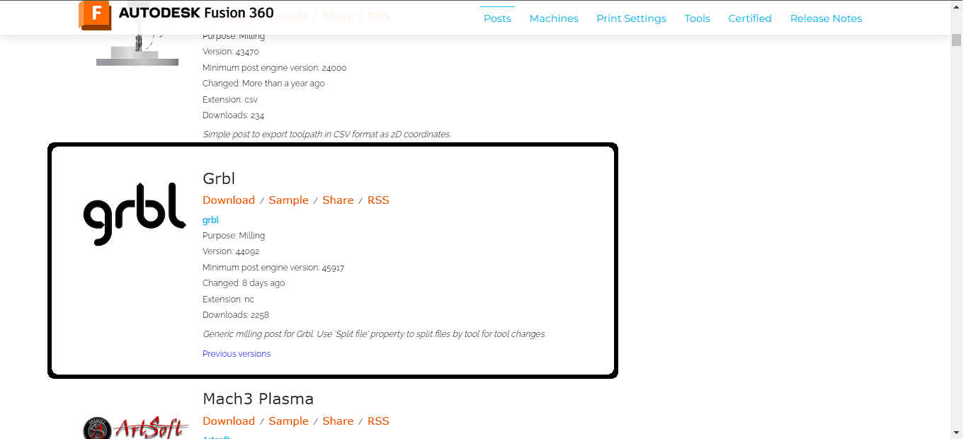
(https://www.youtube.com/watch?v=eY8e4un-wm0)
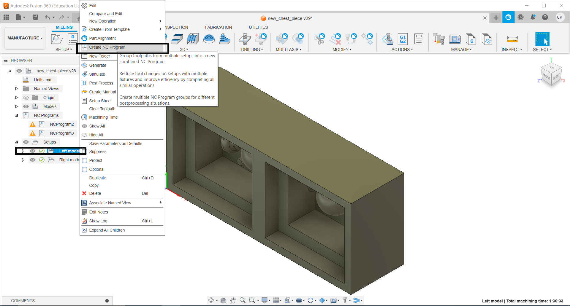
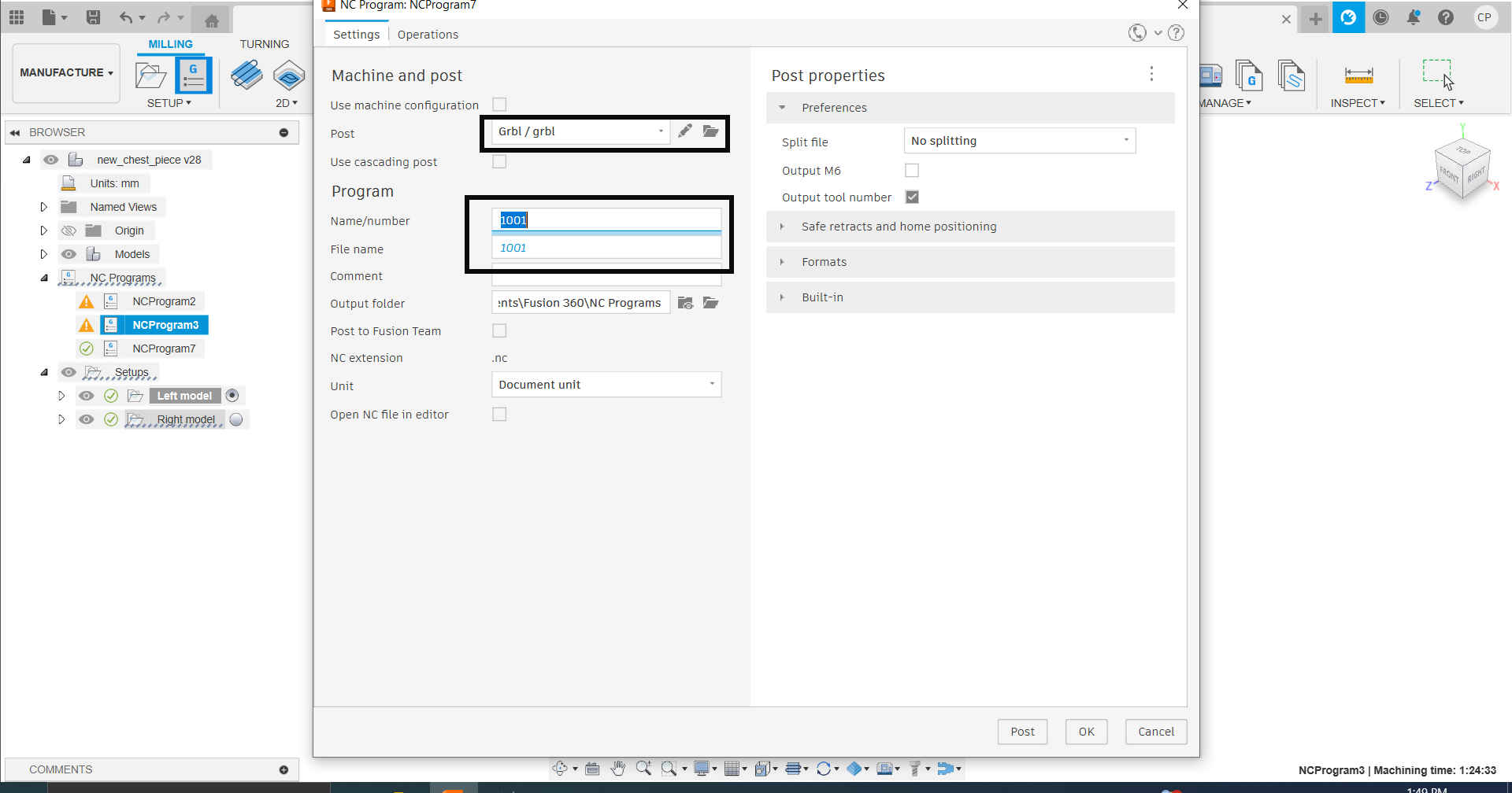
21.Then, I turned the toolpaths for the models on the wax block into NC programs using the grbl post processor.
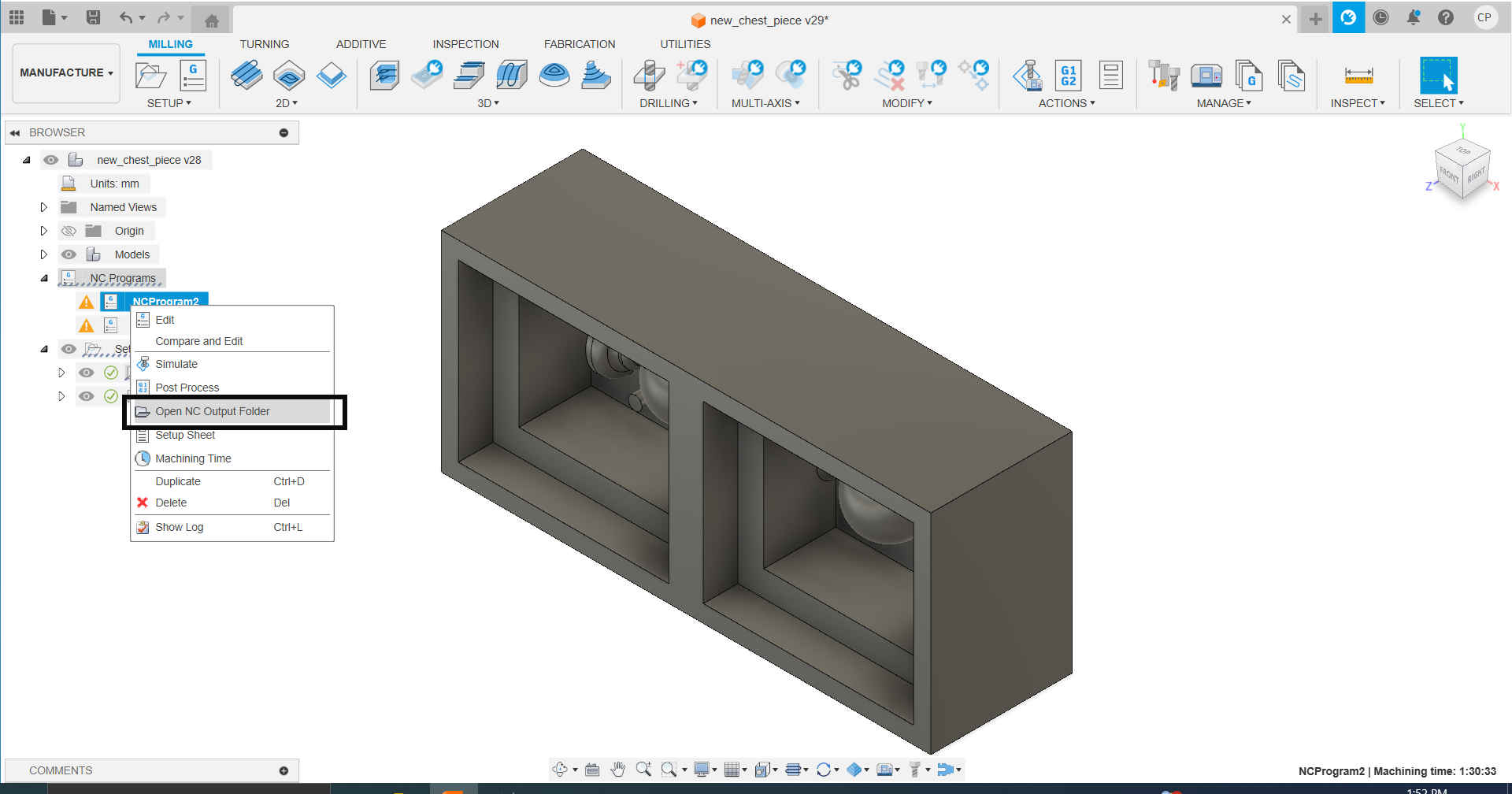
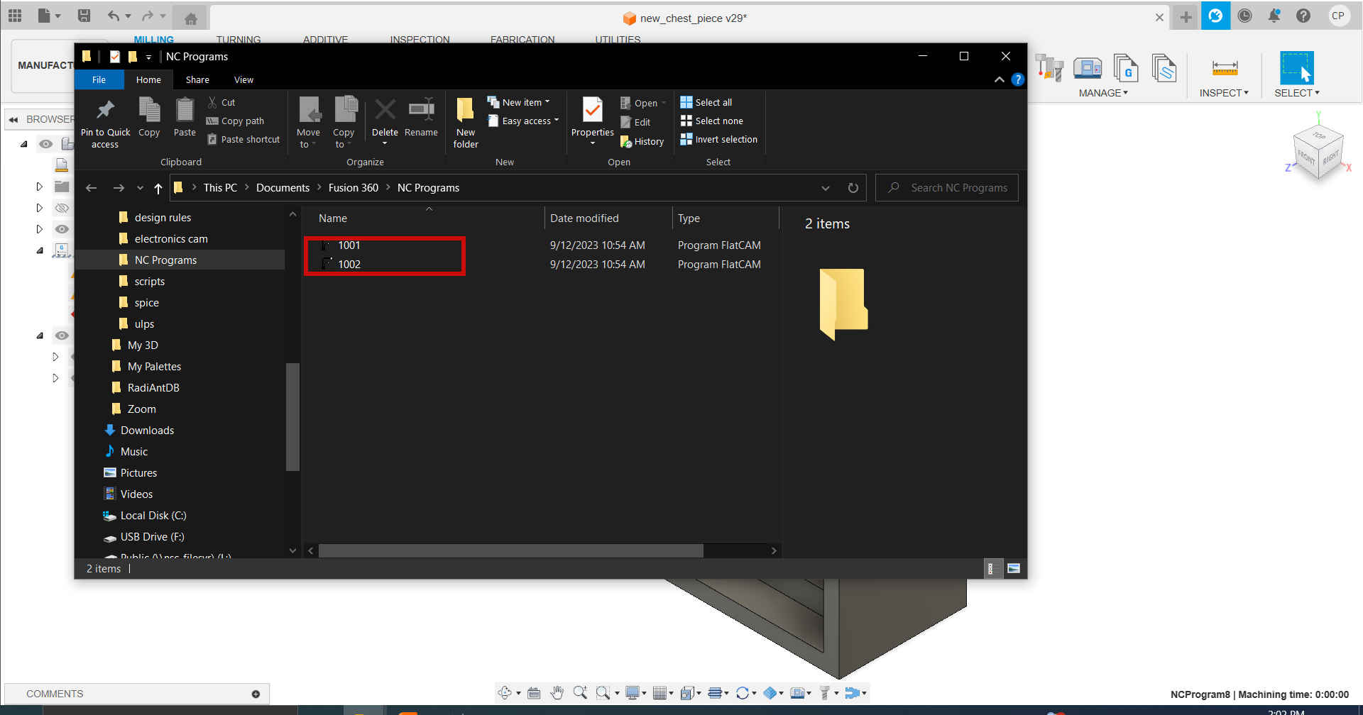
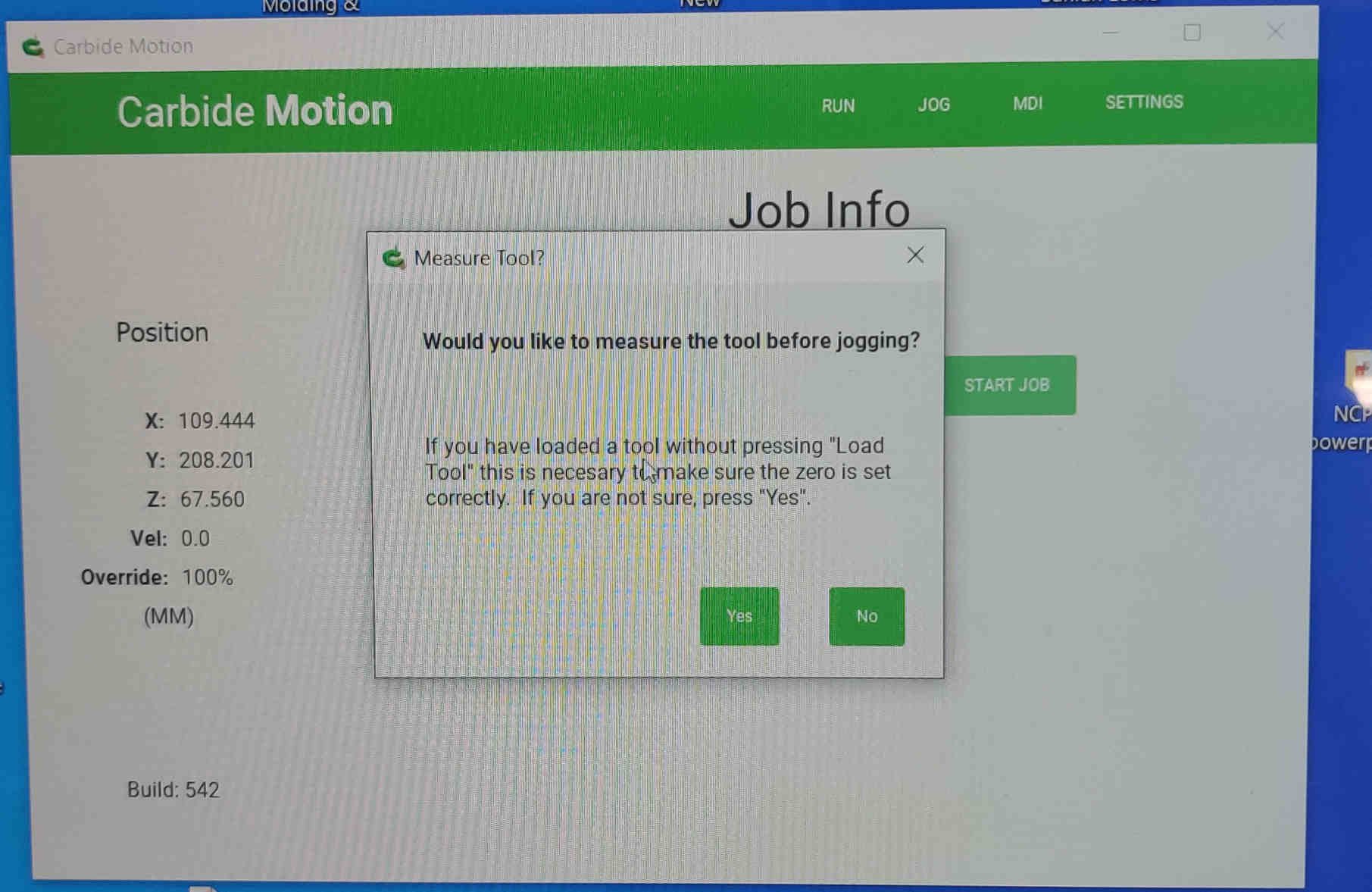
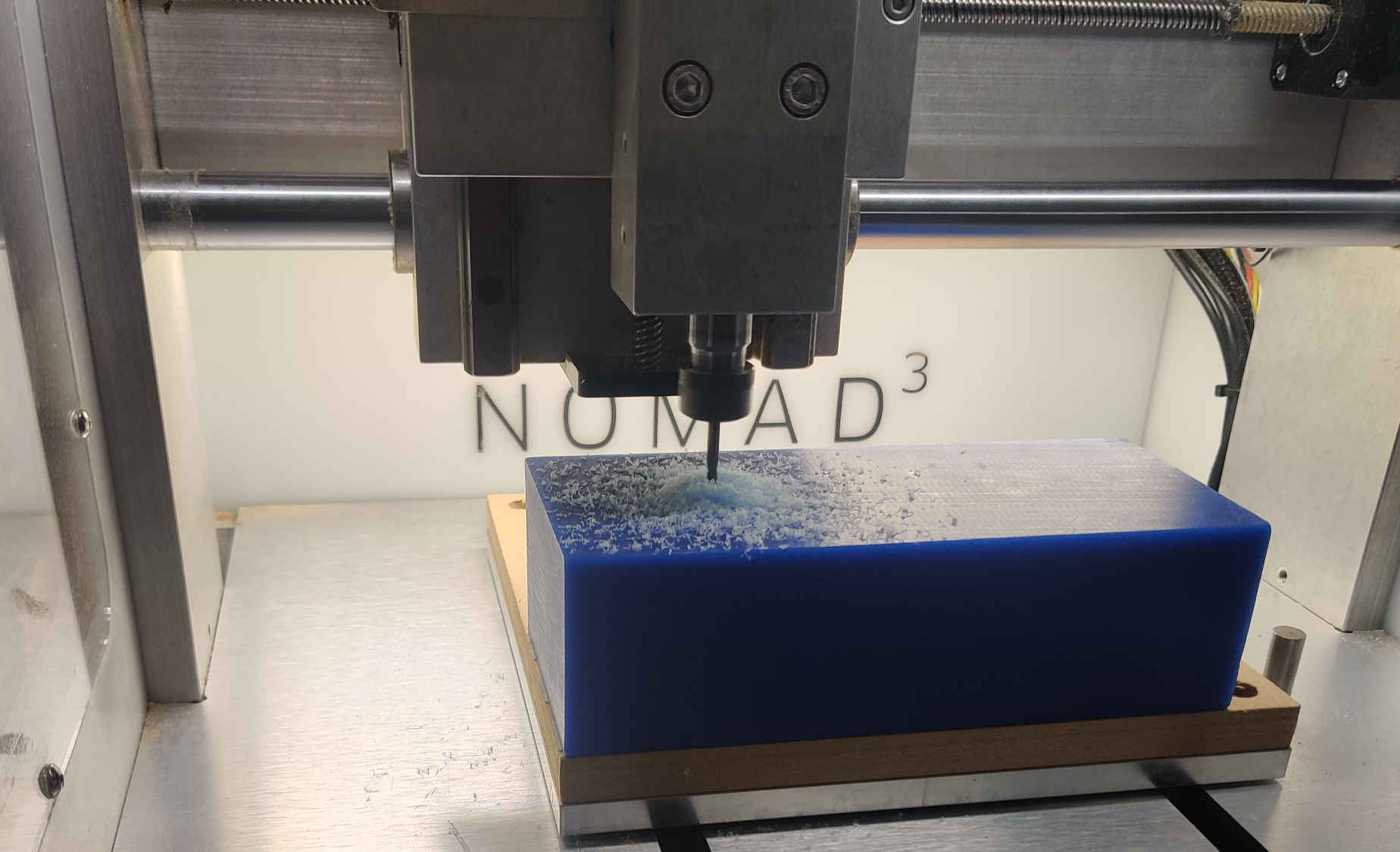
22.Then, the wax block was prepared for the Nomad 3 precision mill, setting confirmed and milled according to the gcode instruction.
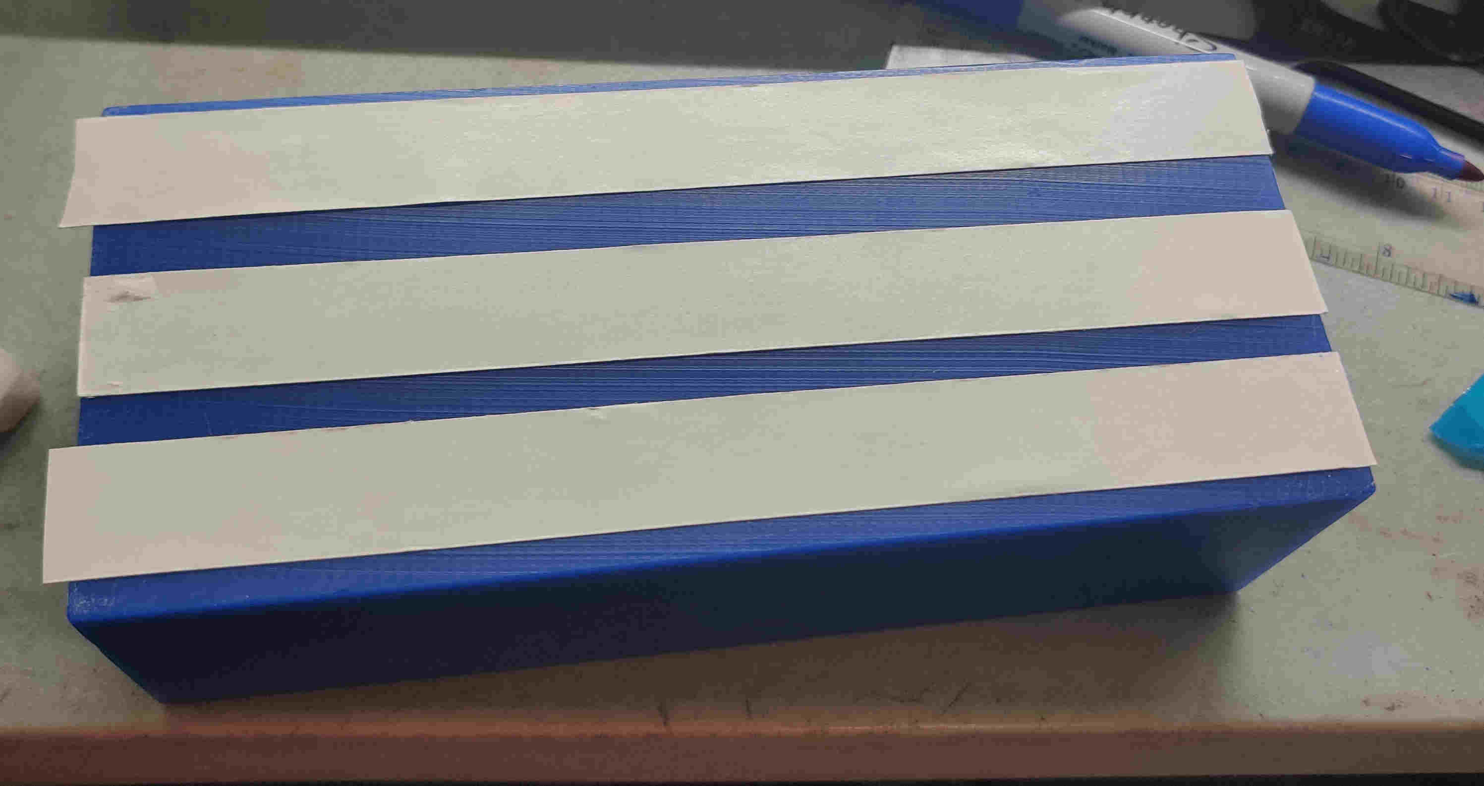
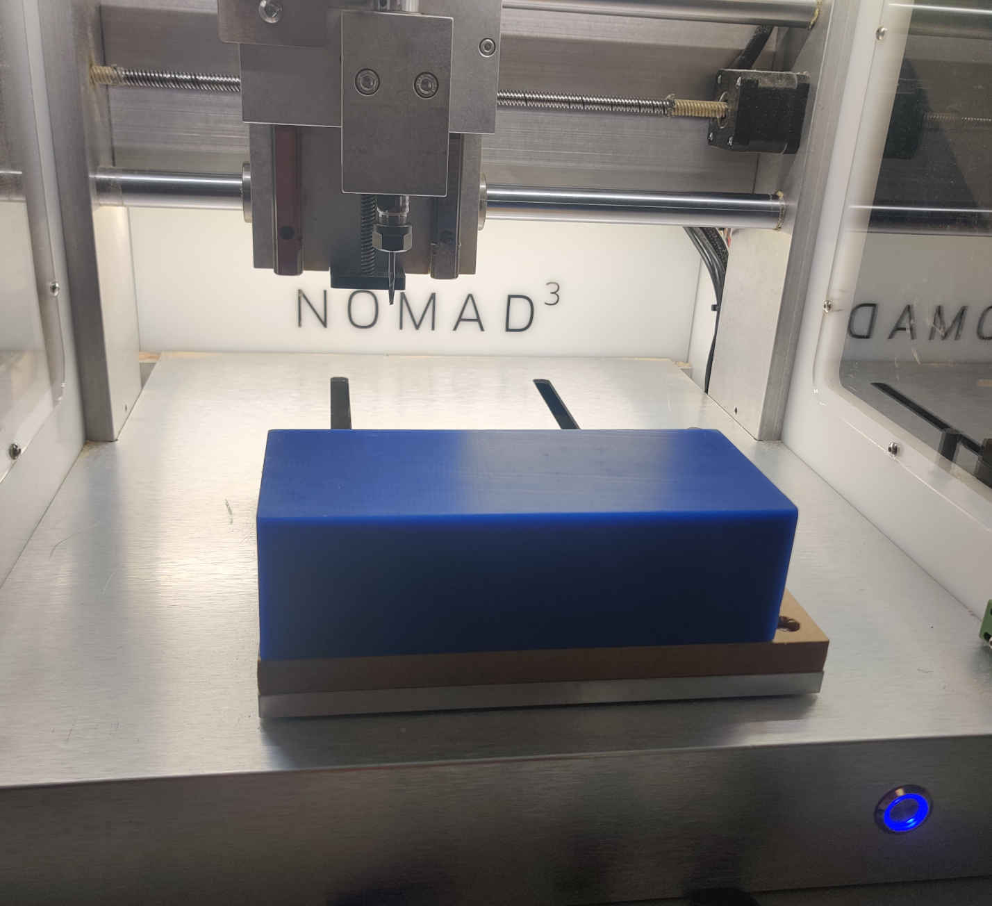
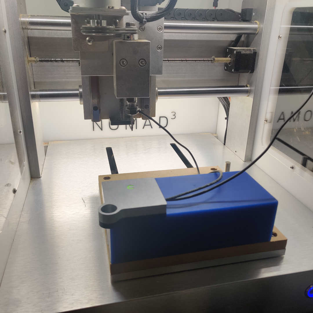
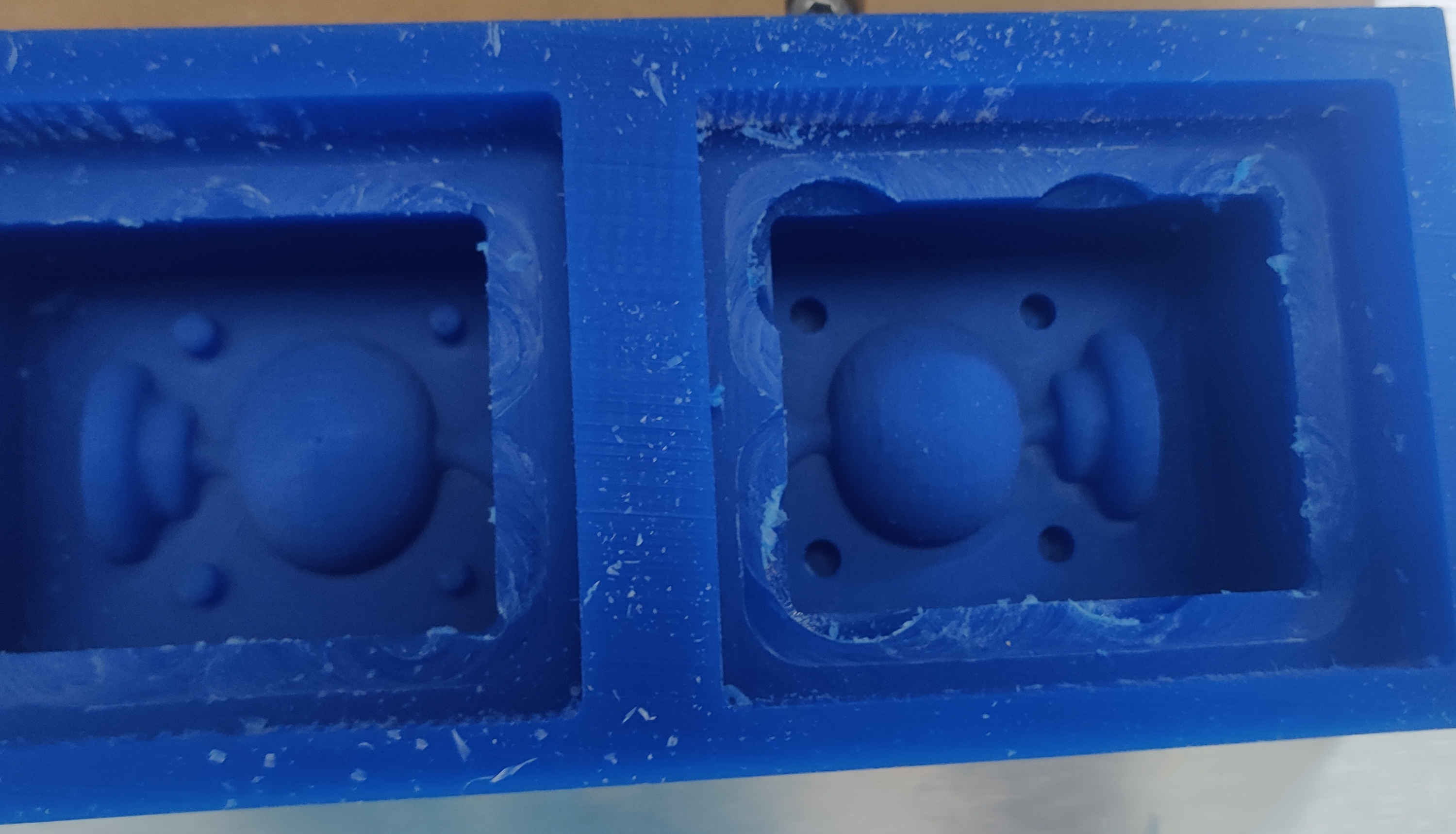
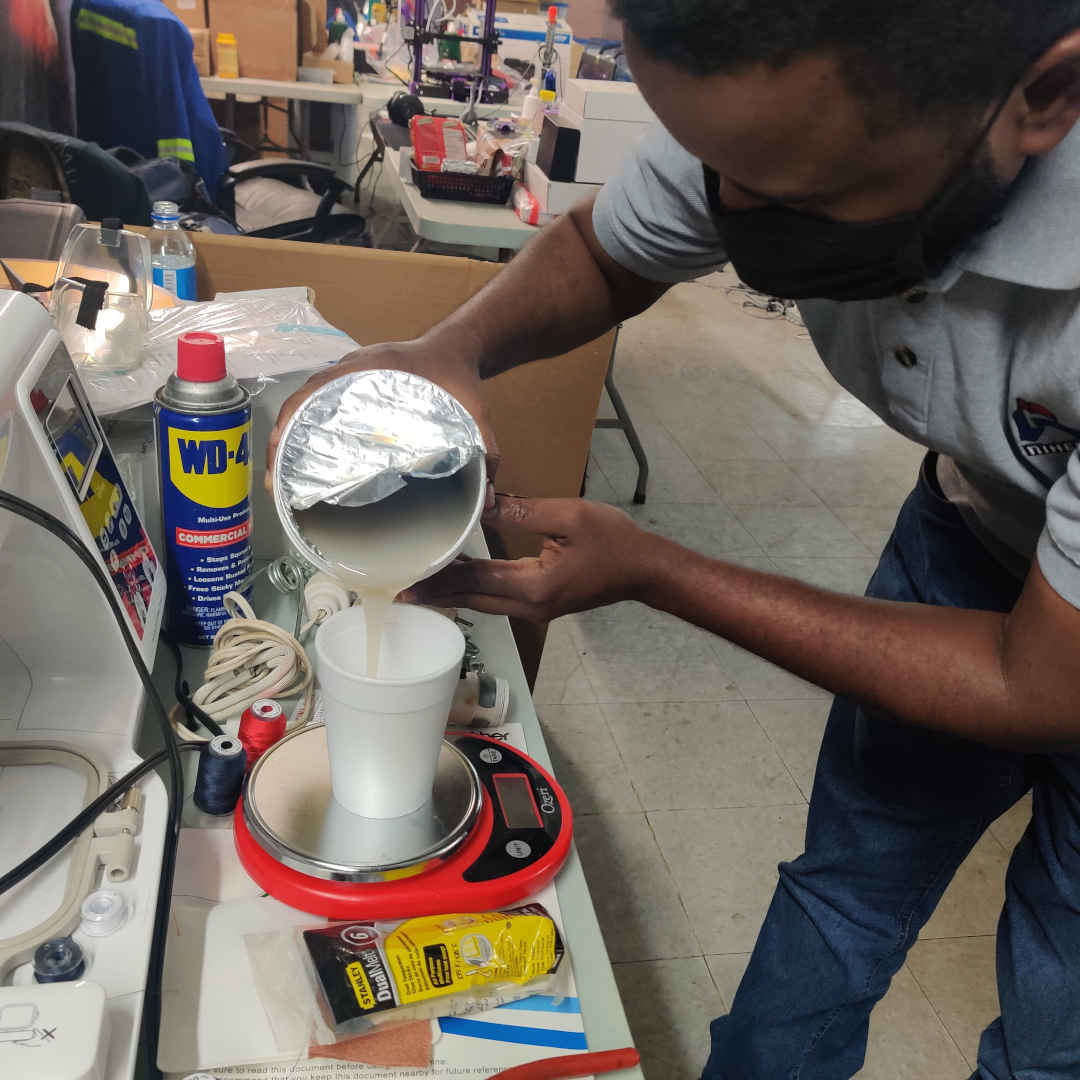
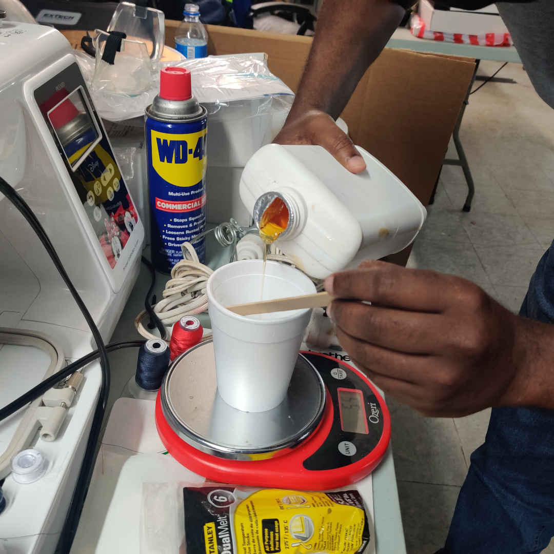
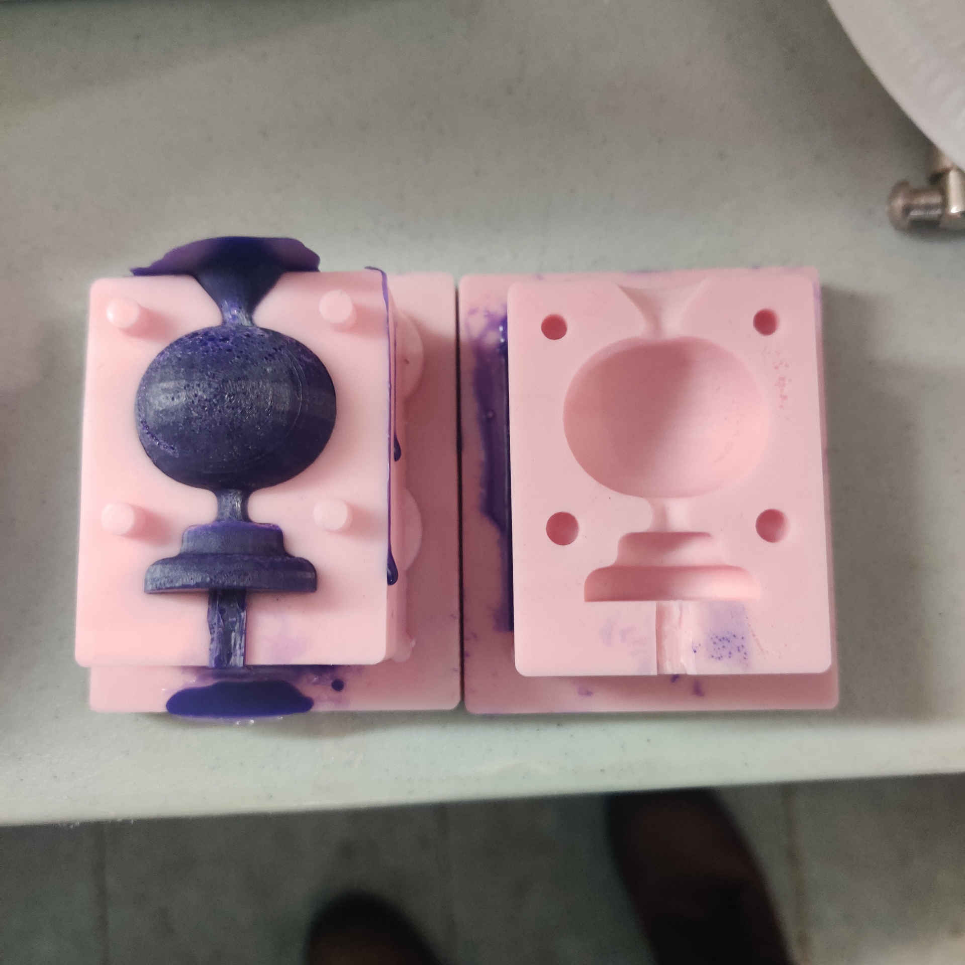
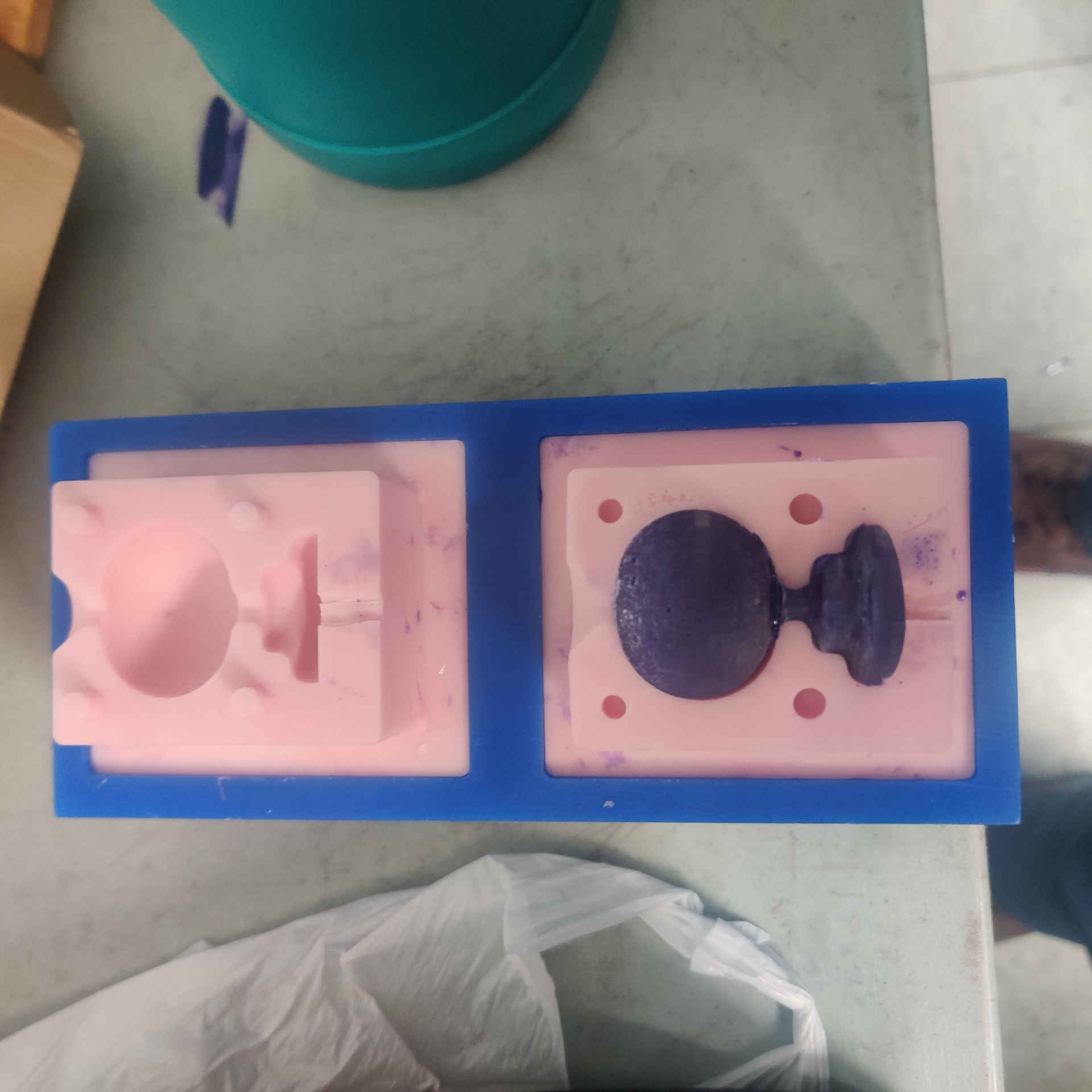
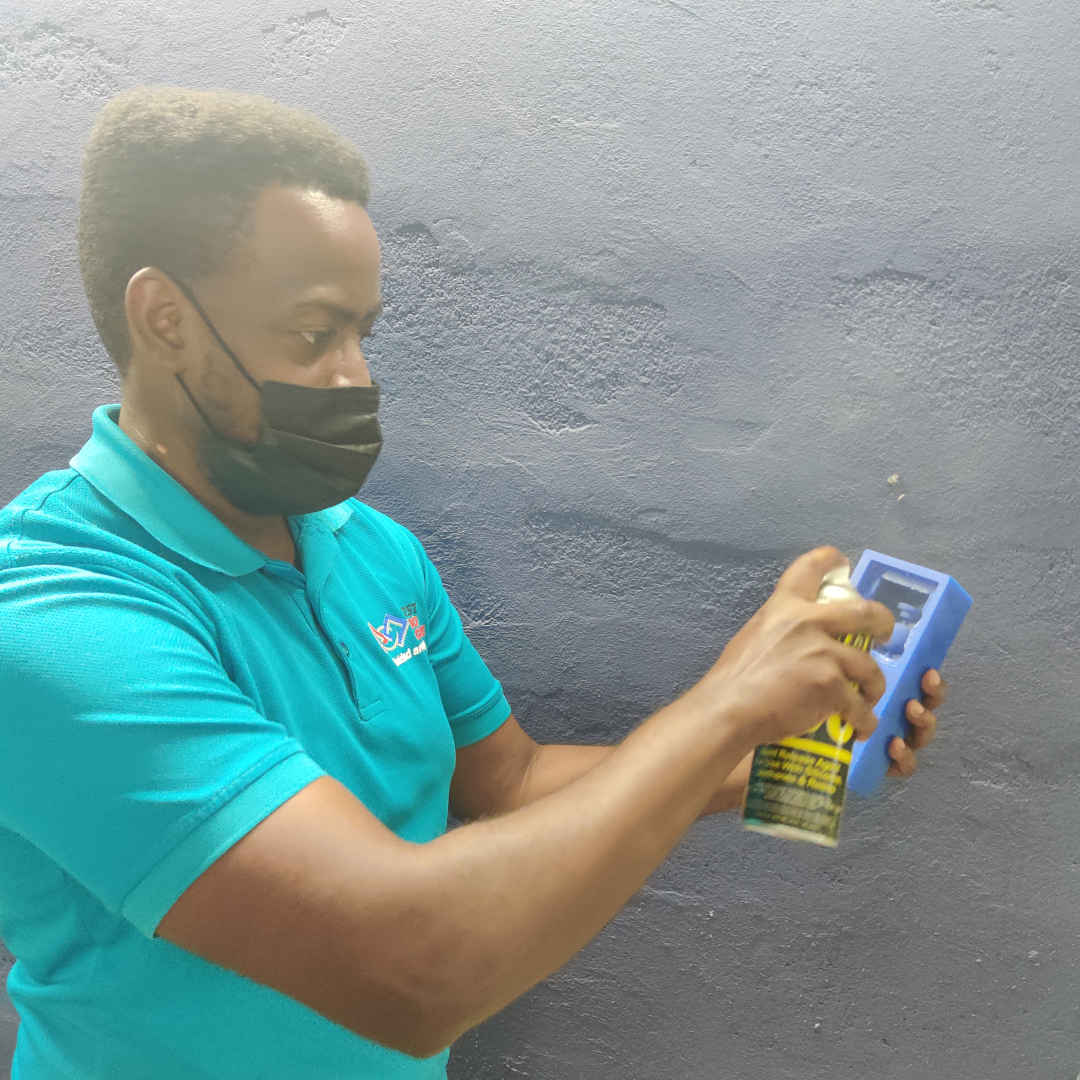
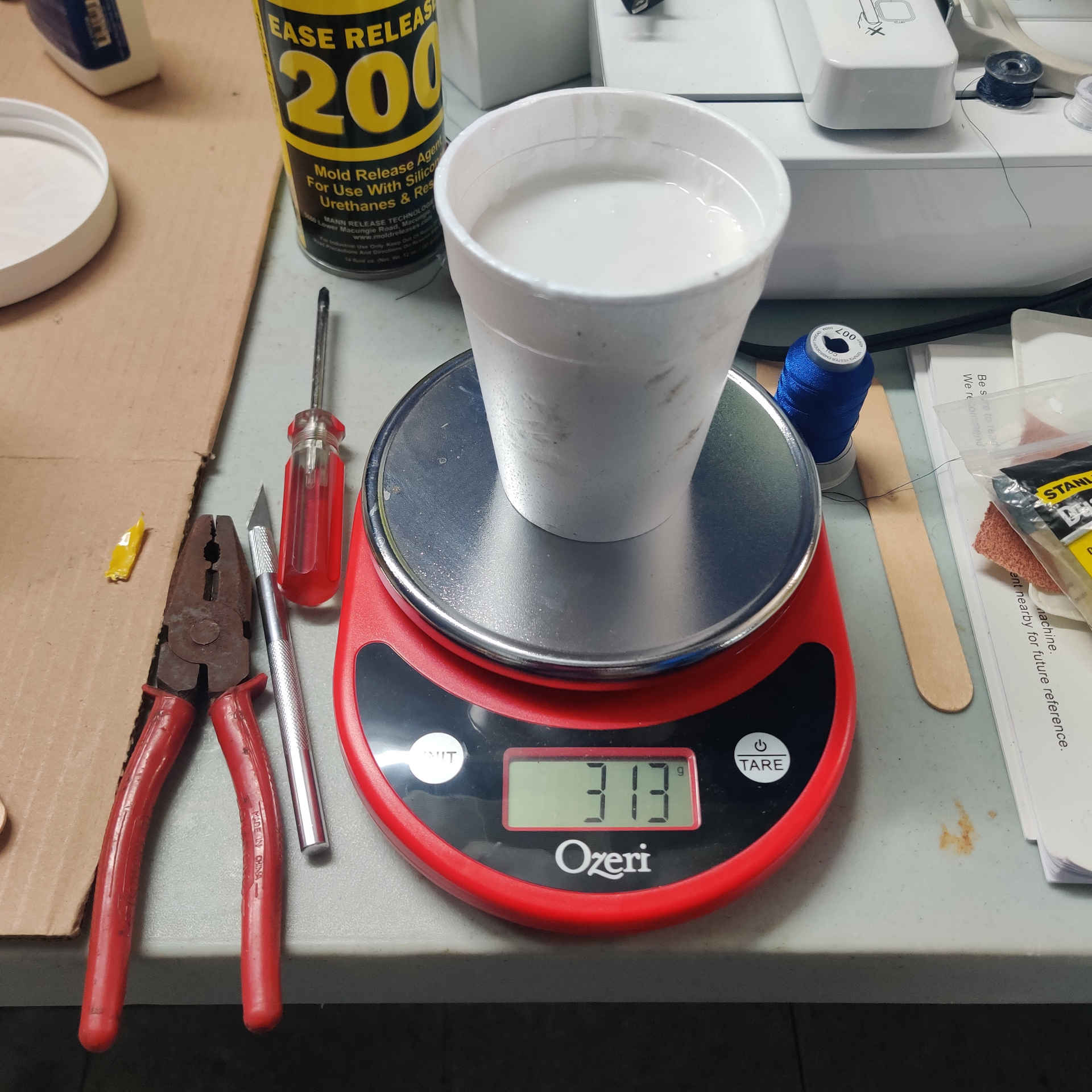
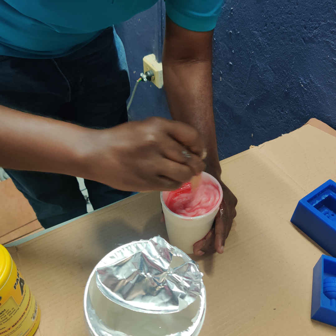
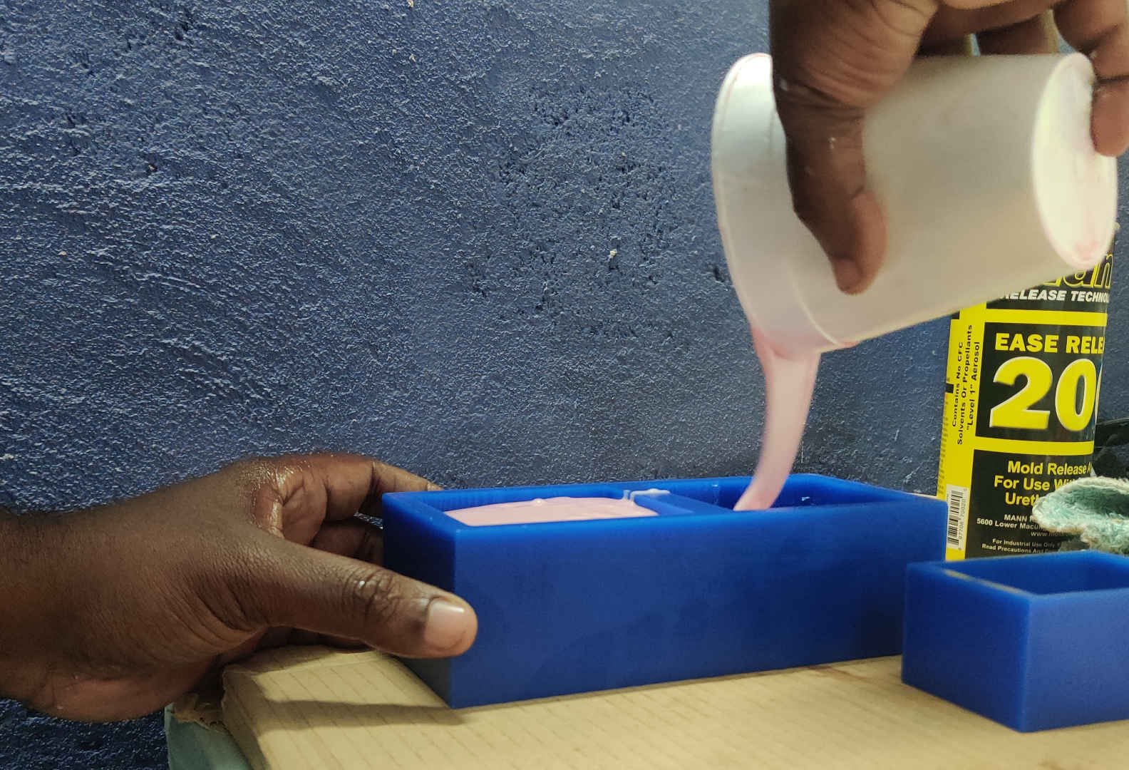
23.Then after milling the wax block of both halves of the model I prepared the material to be used with my model. The material used was Smooth-on 940 Part A and Smooth-on 940 Part B . It was mixed in a 10:1 (A:B) ratio. Easy release sprayed on the wax block prior to pouring the mixture.
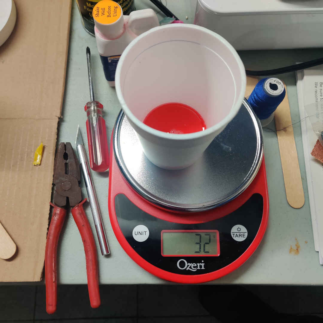
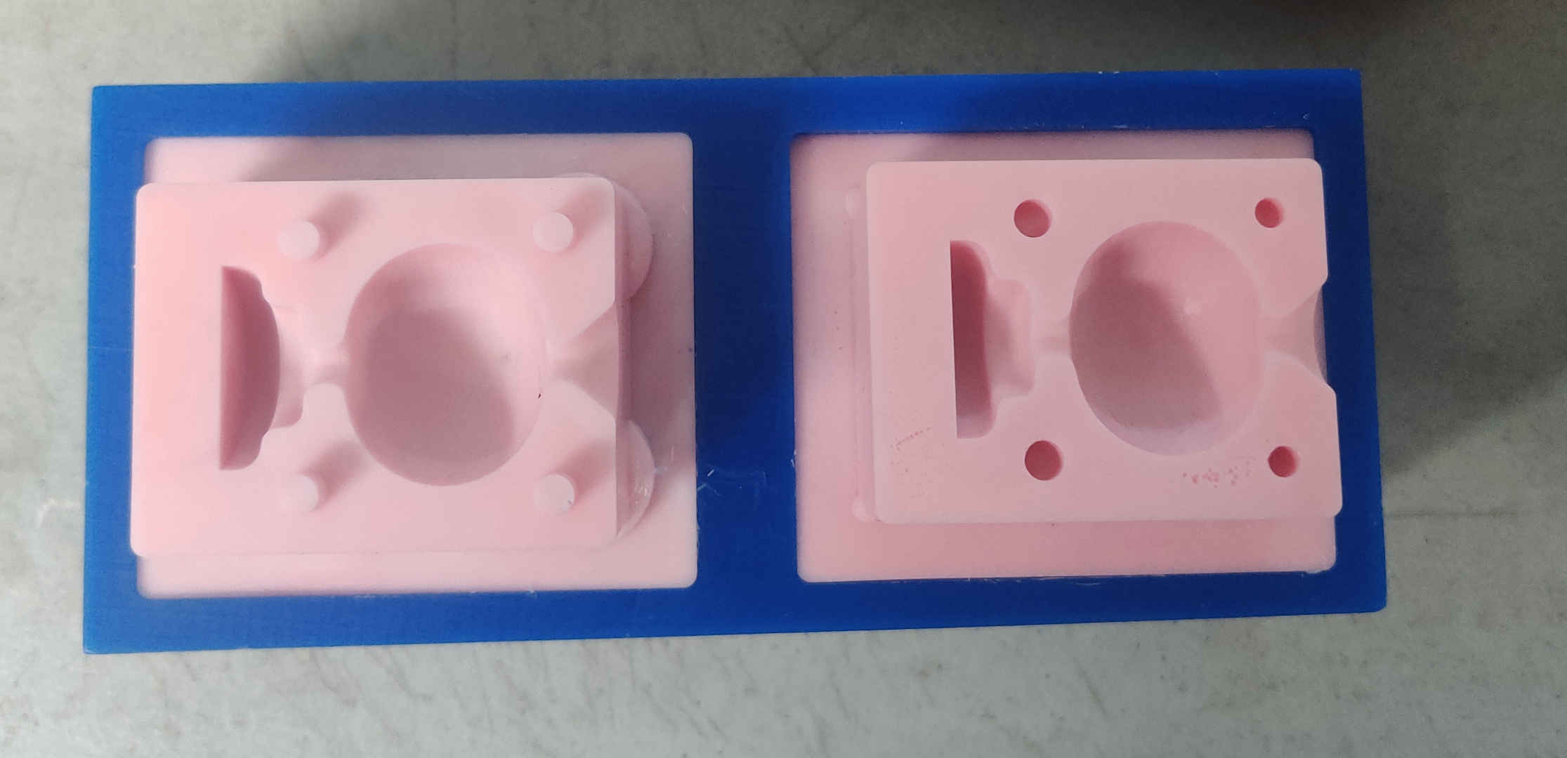
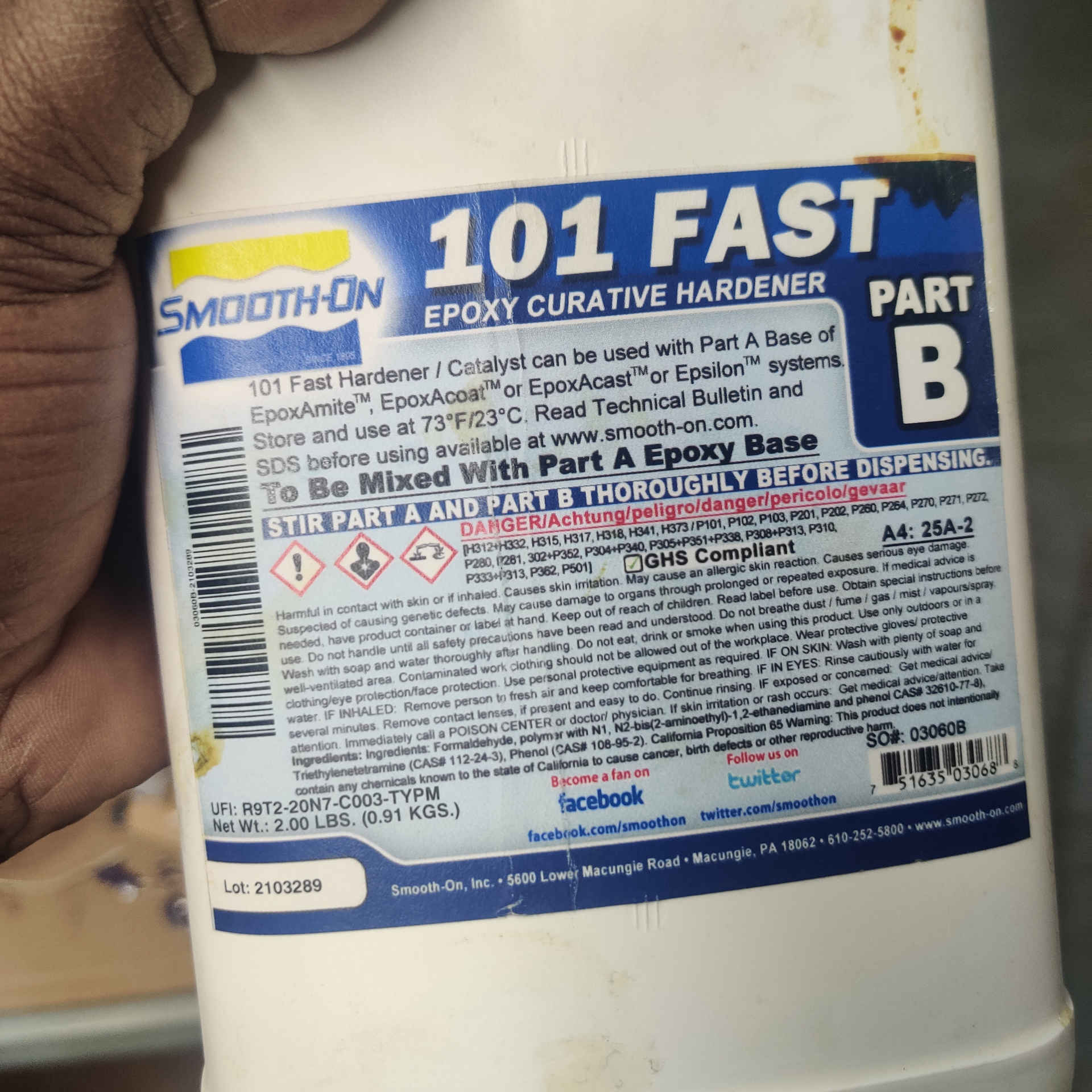
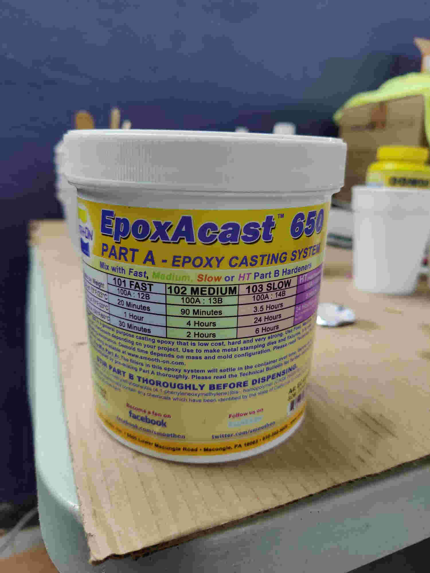
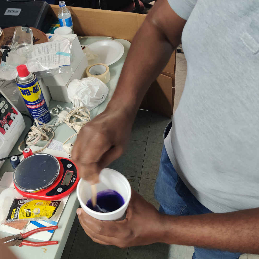
24.Then after the negative molds were created, I prepared to cast. For this process I used EpoxAcast 650 and Smooth-on 101 Fast, also mixed in a 10: 1 ratio. I also added purple pigment to give the part some purple color. A syringe was used to pour the mixture into the negative molds and clamp to hold it tightly together.