7. Electronics design
For this week’s assignment, we looked at Electronics Design.This week looked at the following:
Group assignment:
-
Use the test equipment in your lab to observe the operation of a microcontroller circuit board (as a minimum, you should demonstrate the use of a multimeter and oscilloscope).
-
Document your work on the group work page and reflect what you learned on your individual page.
Individual assignment:
Design a development board to interact and communicate with an embedded microcontroller
Group Assignment Reflection:
From this group assignment I learned that there are a variety of electronic testing equipment (multimeters, DC power supplies ,etc) that are used in electronics/electrical for testing and troubleshooting purposes.Micro-controllers can be complex components depending your knowledge of them. They are differences from the schematic view and physical layout of the connected pins which can sometimes lead to confusion. therefore it is always advised to look at the pinout diagram fro the micro controller to get a true representation of the layout.
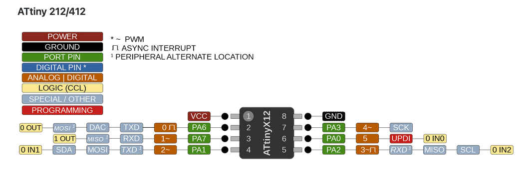
ATtiny412 is a 8bit microcontoller with low power comsumption. It forms part of the AVR microcontroller family, 4KB of flash memory for program storage and 256 bytes of SRAM for data storage.
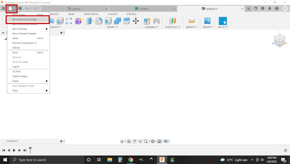
1.Firstly, I opened Fusion360 and in the file drop-down menu, I selected new electronics design.
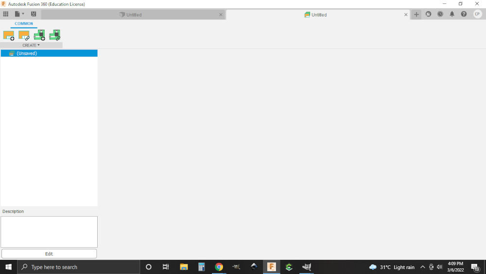
2.Then I selected new schematic. This is the place where the schematic will be created.
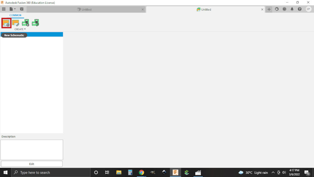
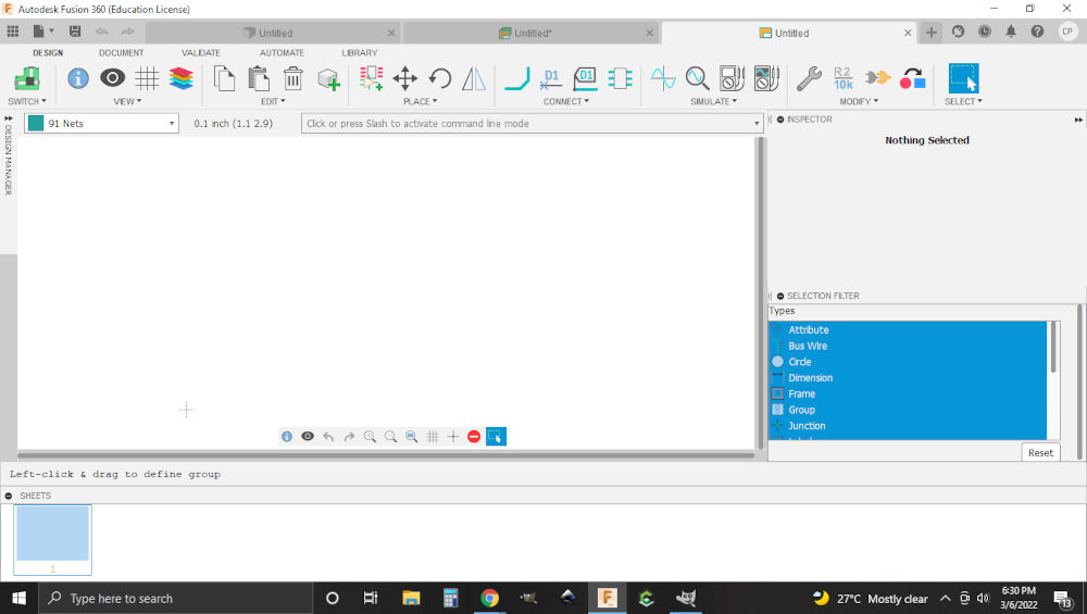
Note. Apart from new schematic you can also link to an existing schematic or choose a new PCB or link to an existing PCB.
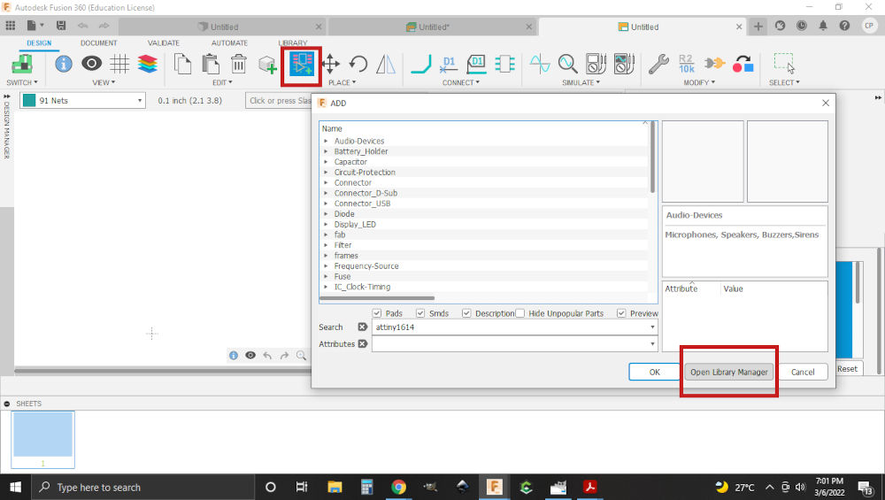
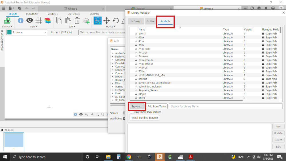
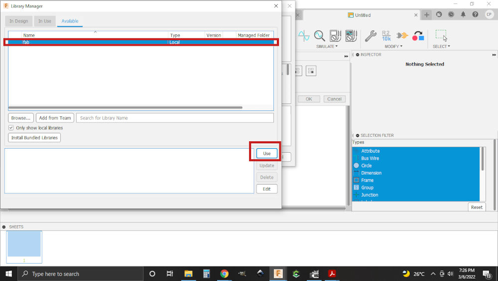
3.Then I included the Fab Academy Library to fusion. I clicked on the following link Fab Libraryfound in the class schedule and downloaded the fab.lbr file for eagle (as I am using Fusion360). Then I added the library to Fusion 360.
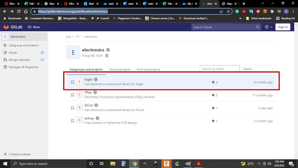
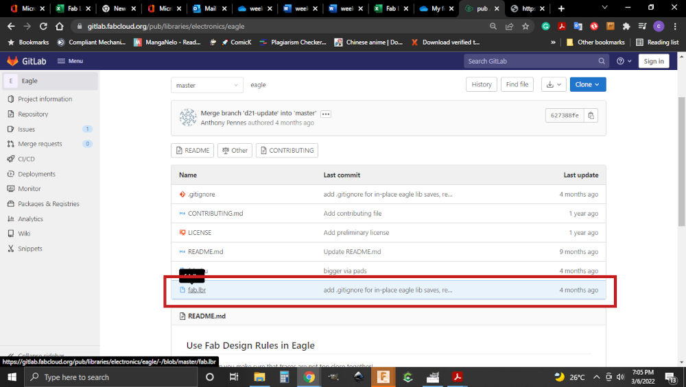
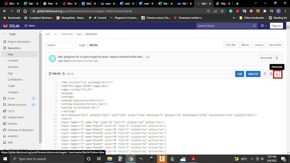
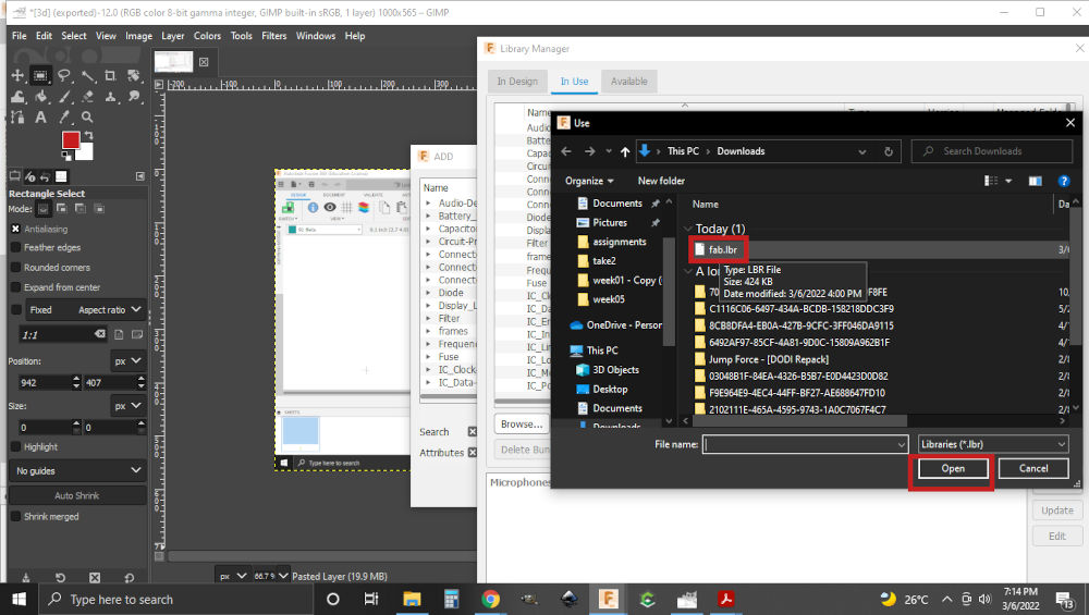
Note. Libraries can either be downloaded or added from the software
4.Then I began adding the components I would need for the circuit. The components used were ATtiny412 ,1uF capacitor, 1k resistor(2), LED, switch, FTDI and UPDI connector.
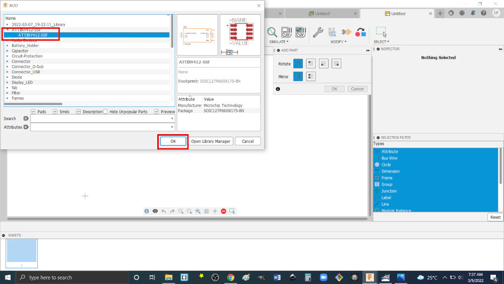
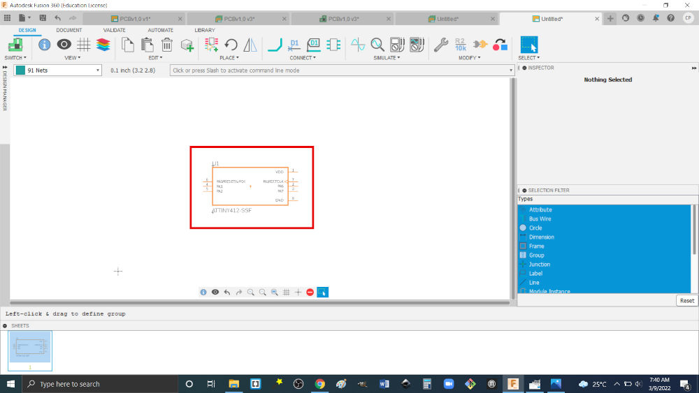
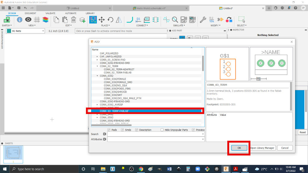
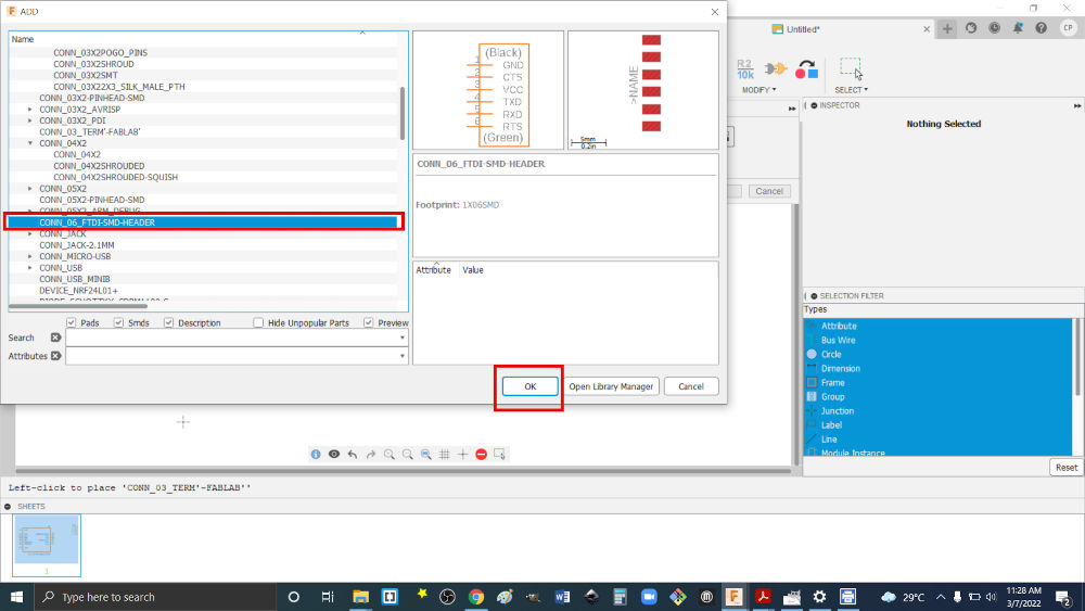
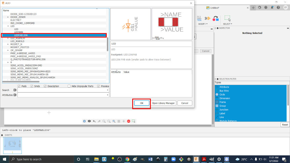
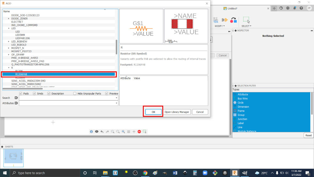
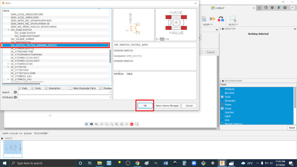
Note. Components may not be found from simply searching but looking creatively.
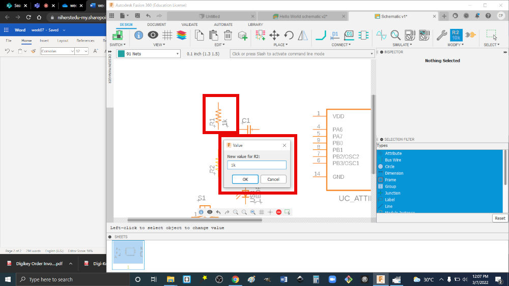
5.Then I added values to the components that required it e.g. resistor, capacitor.
6.Then I placed the connections between components.
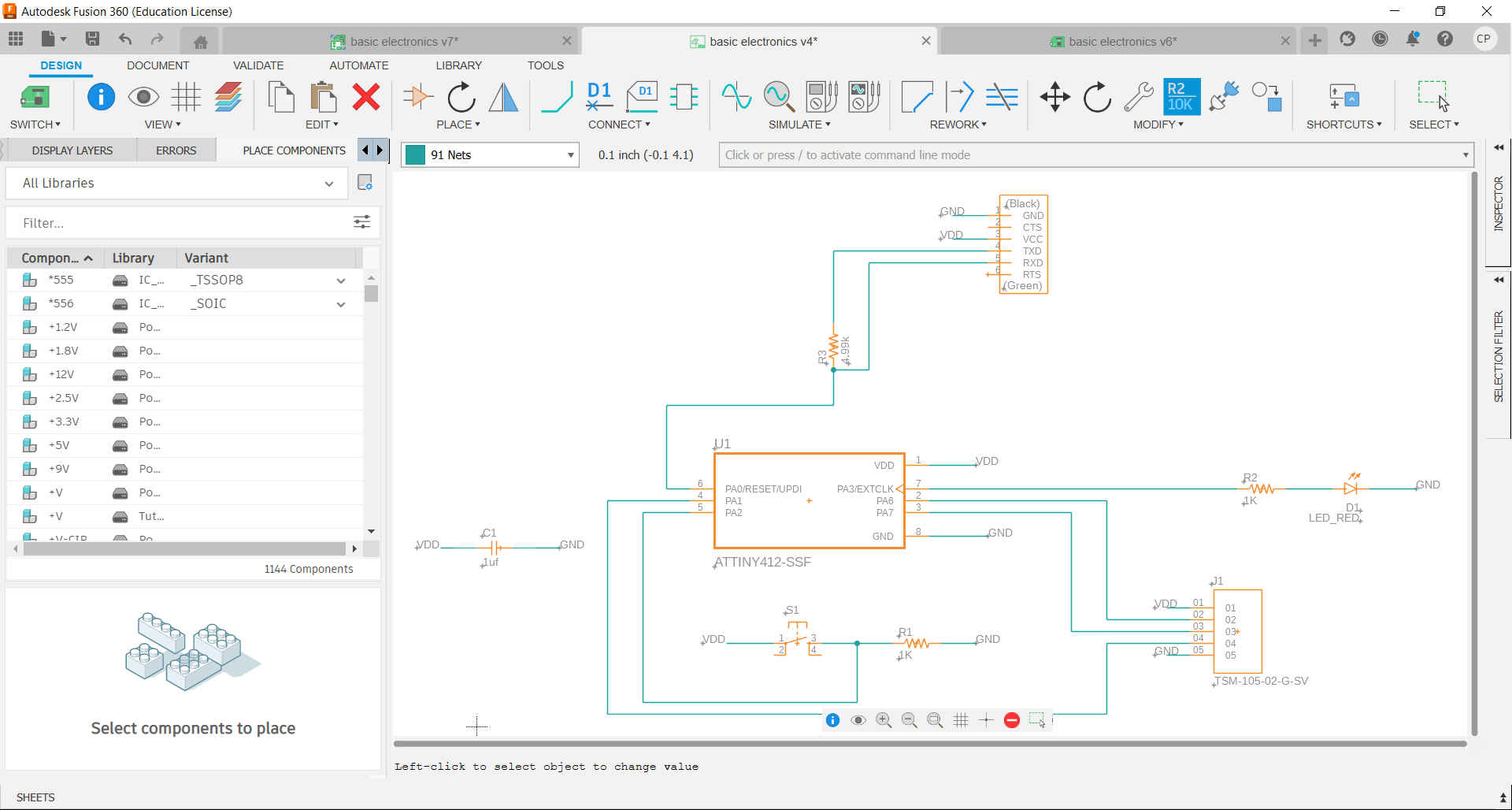
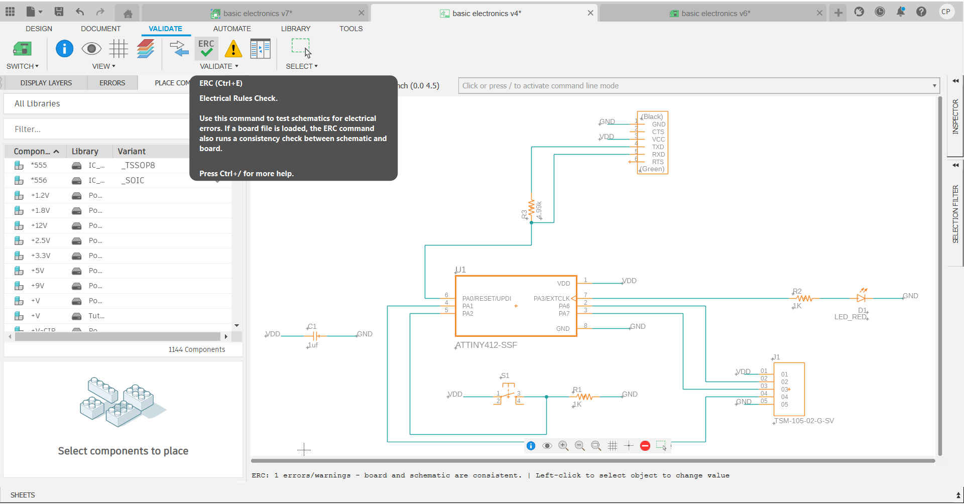
7.Then I added the required supply and ground. After which I validated the circuit to ensure there were not any unforeseen errors.
8.Then I created my PCB board by selecting switch to PCB document.
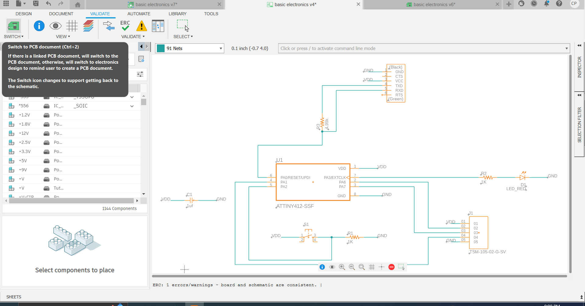
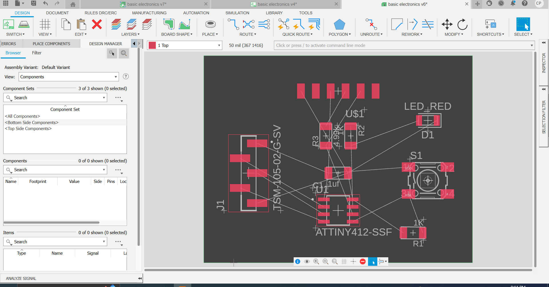
Note. When entering the PCB document, all components will be placed and have ghost traces.
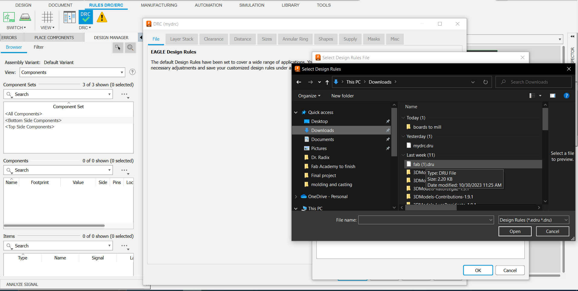
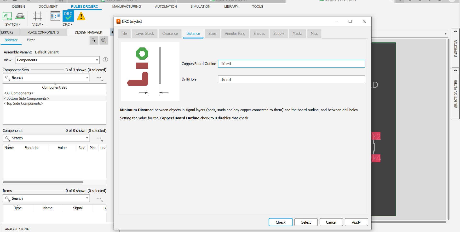
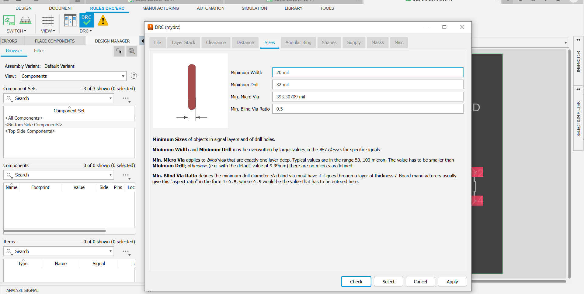
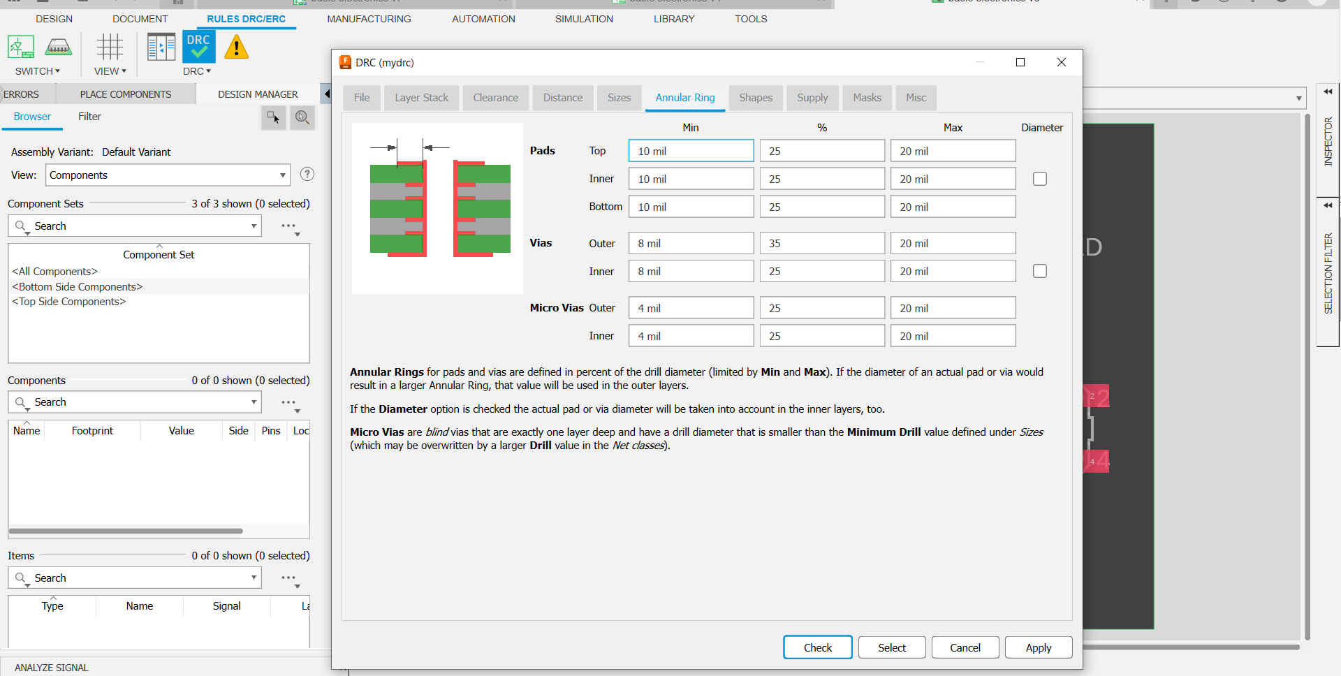
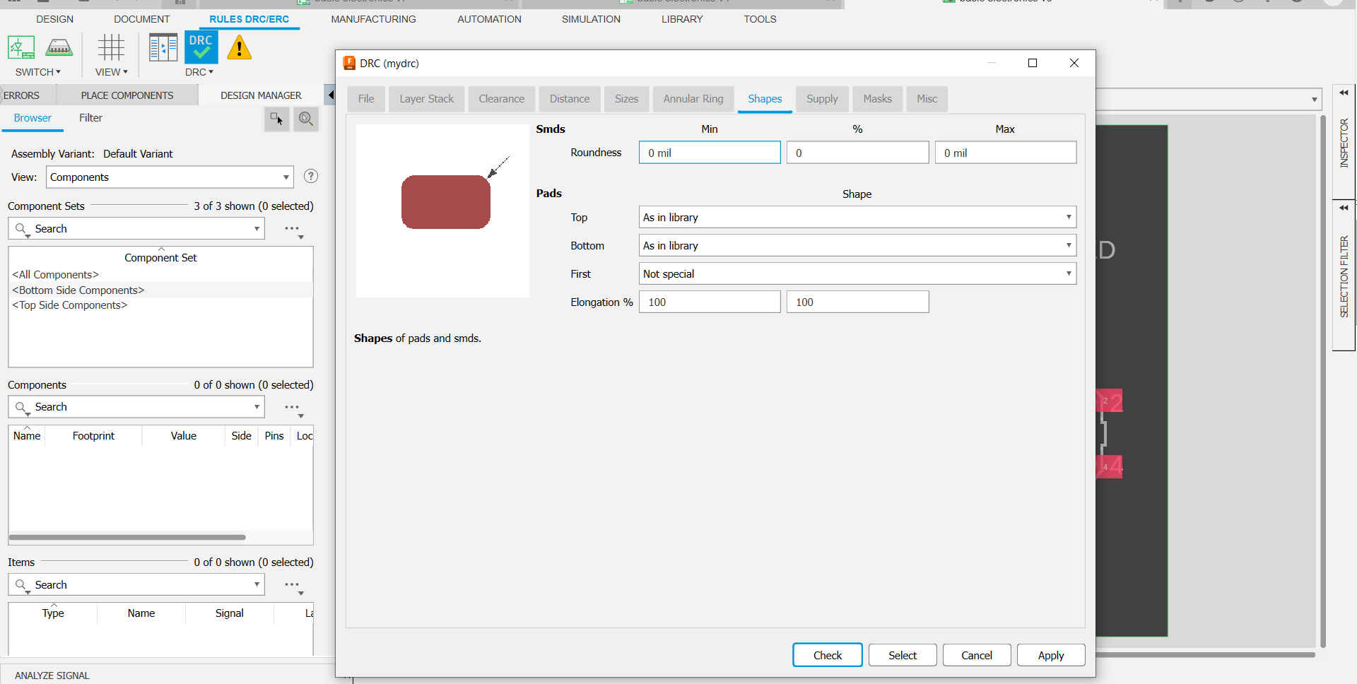
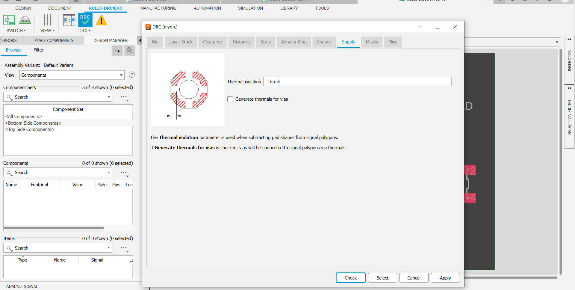
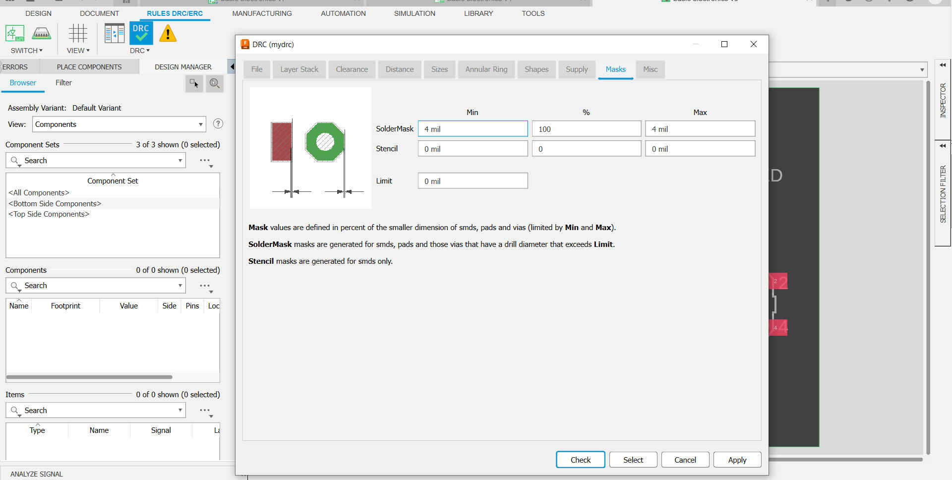
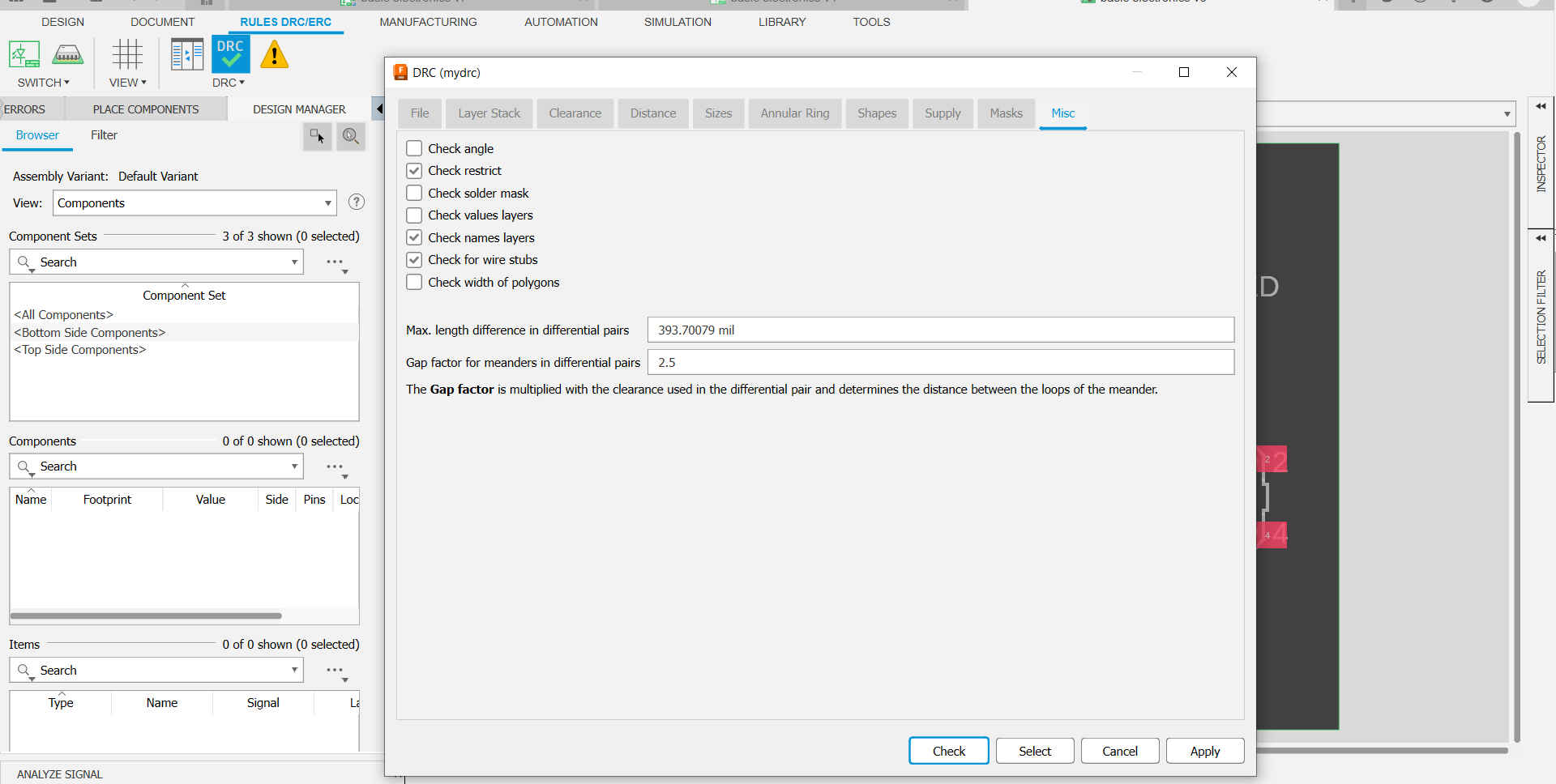
9.Then I added the FabLab design rules to fusion.
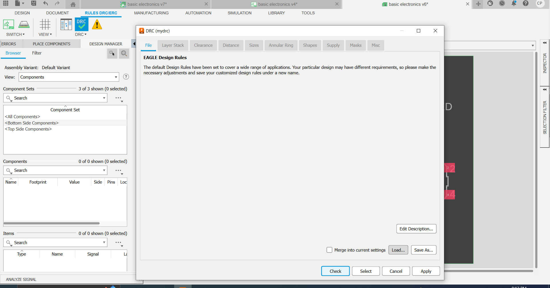
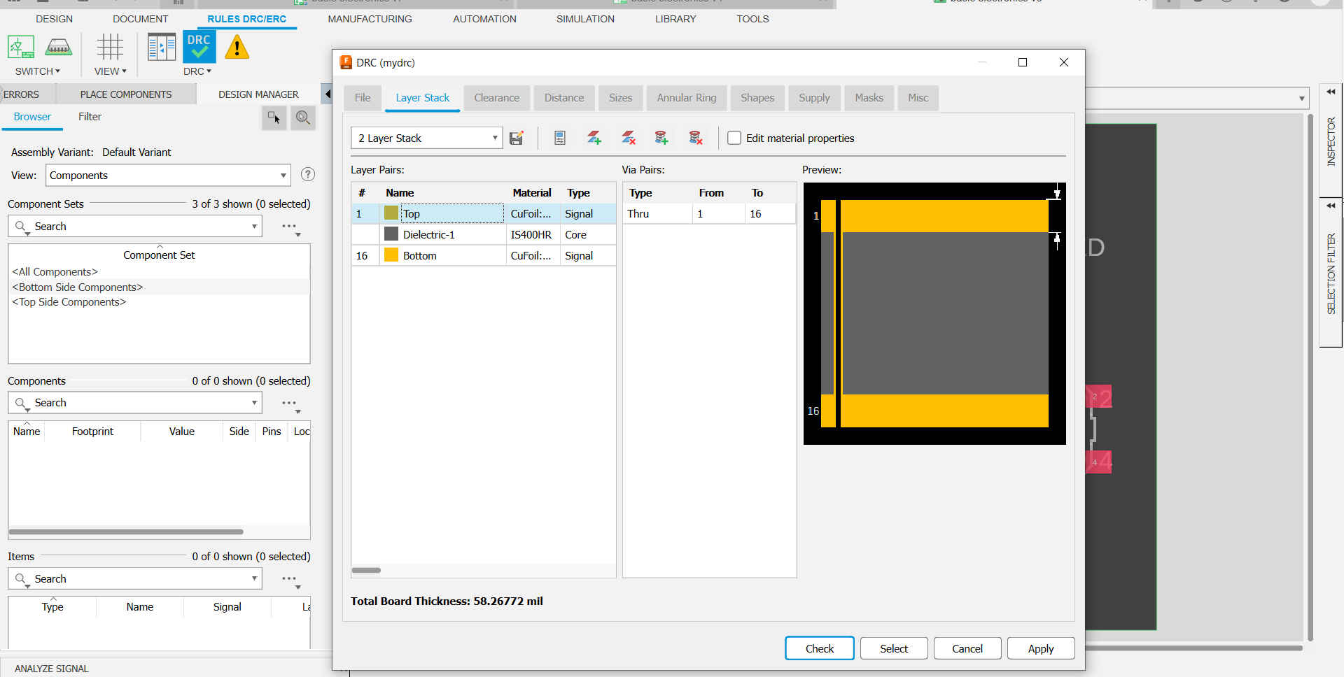
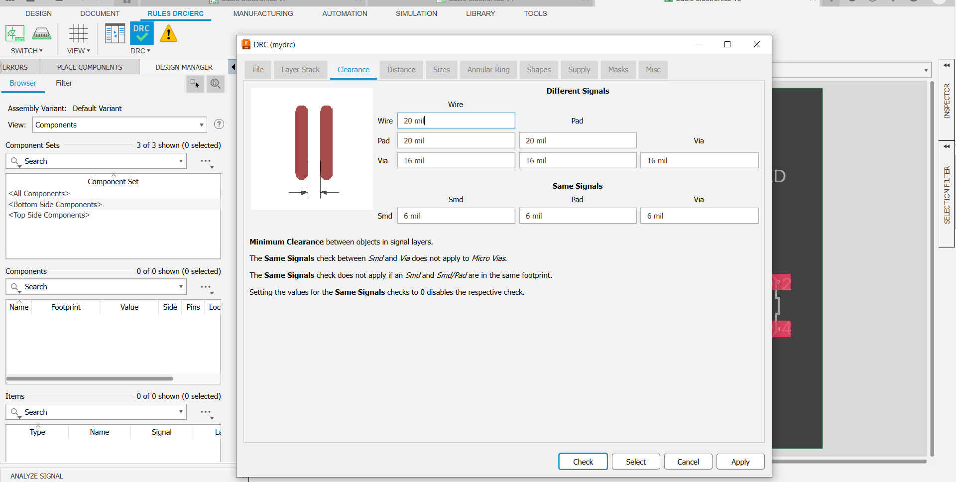
10.Then I reviewed the Design rules (DRC).
11.Then I ran the autorouter using the design rules to create the traces fro my board.
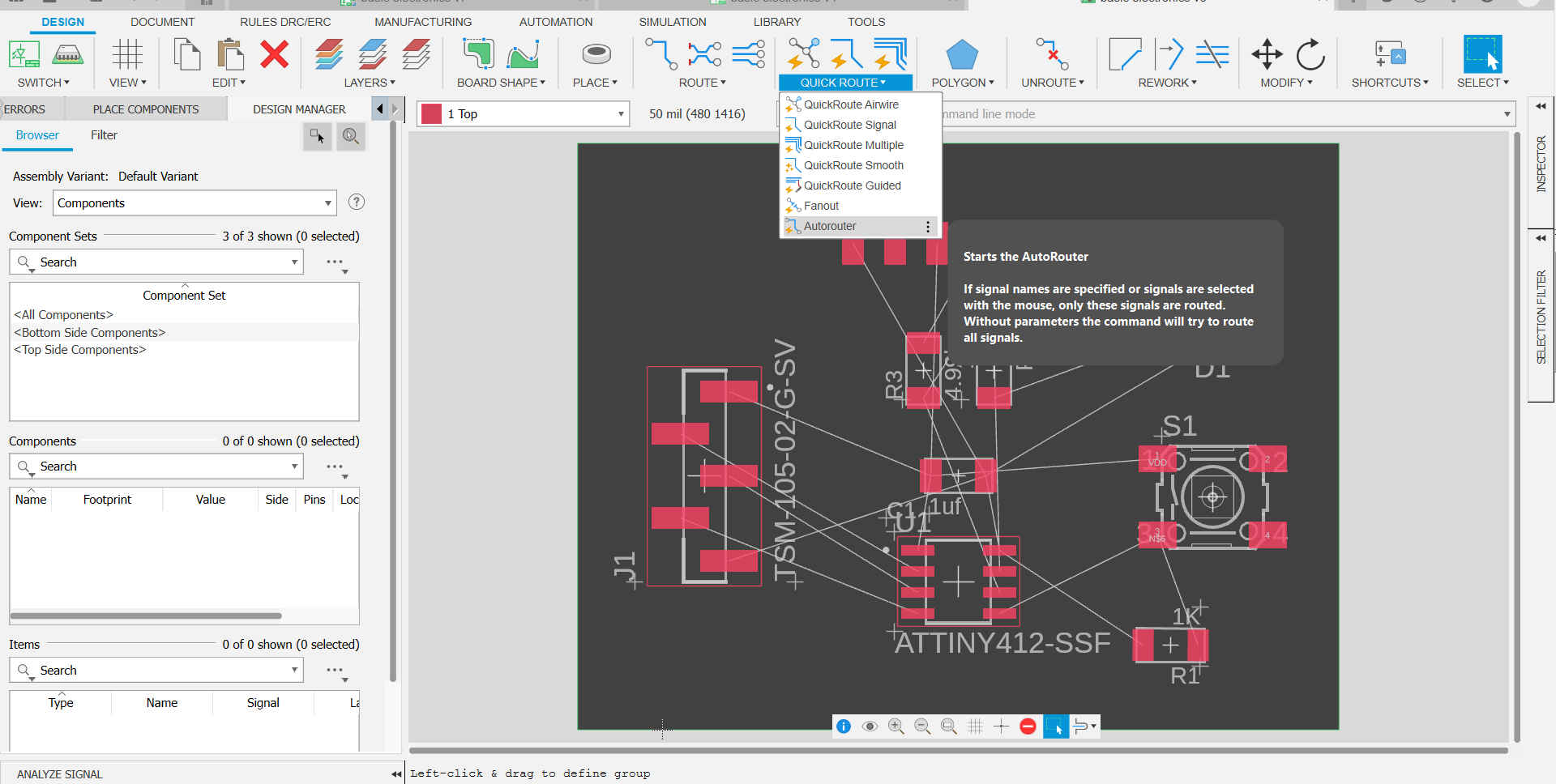
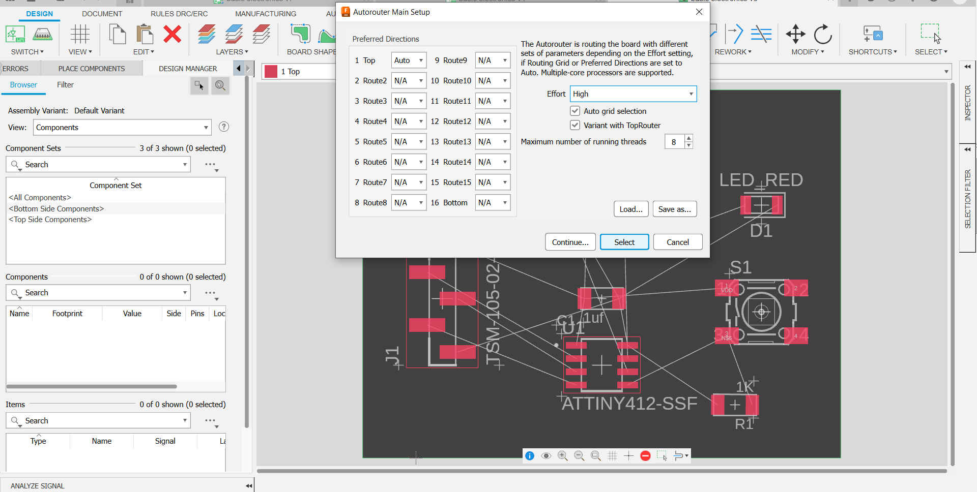
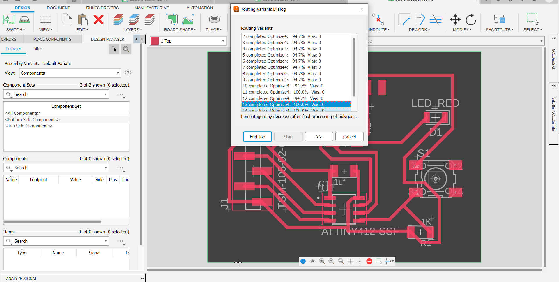
NB. Select the route that is at 100% or select the route that you like and make chnages if required.