Use the test equipment in your lab to observe the operation of a microcontroller circuit board.
At the NIHERST Fablab we had access to:
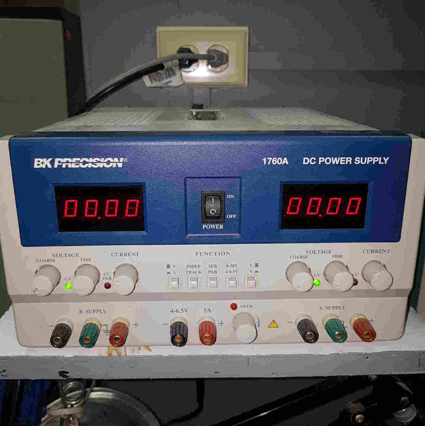
A regulated power supply provides a constant output voltage, independent of the output current. A regulated power supply with multiple regulators can offer multiple output voltages for operating different devices.
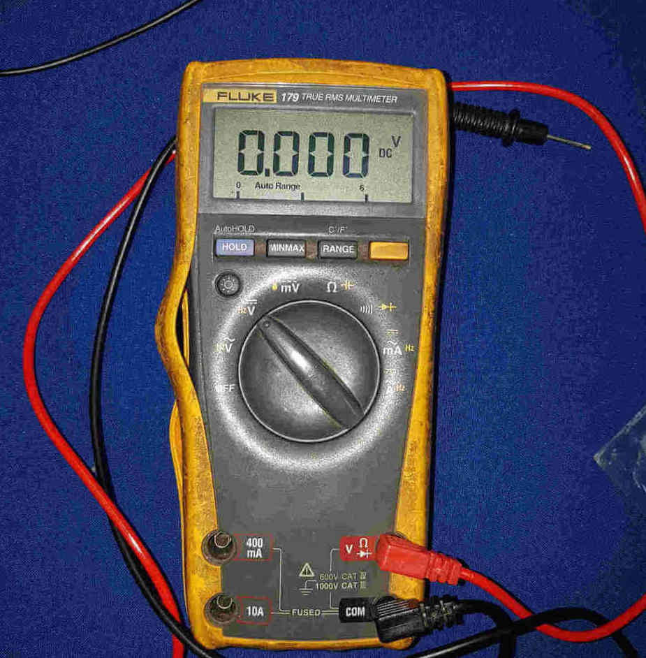
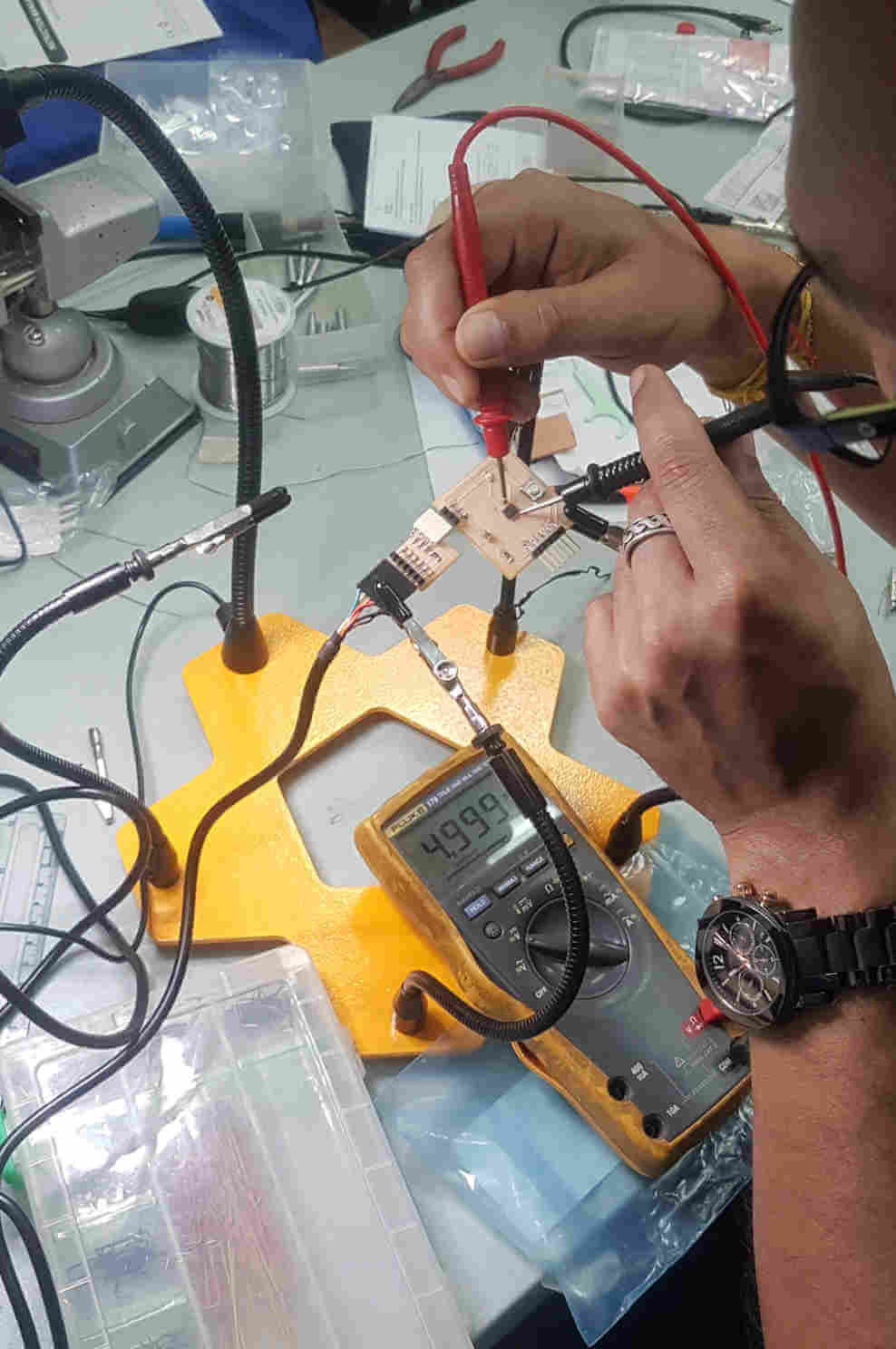
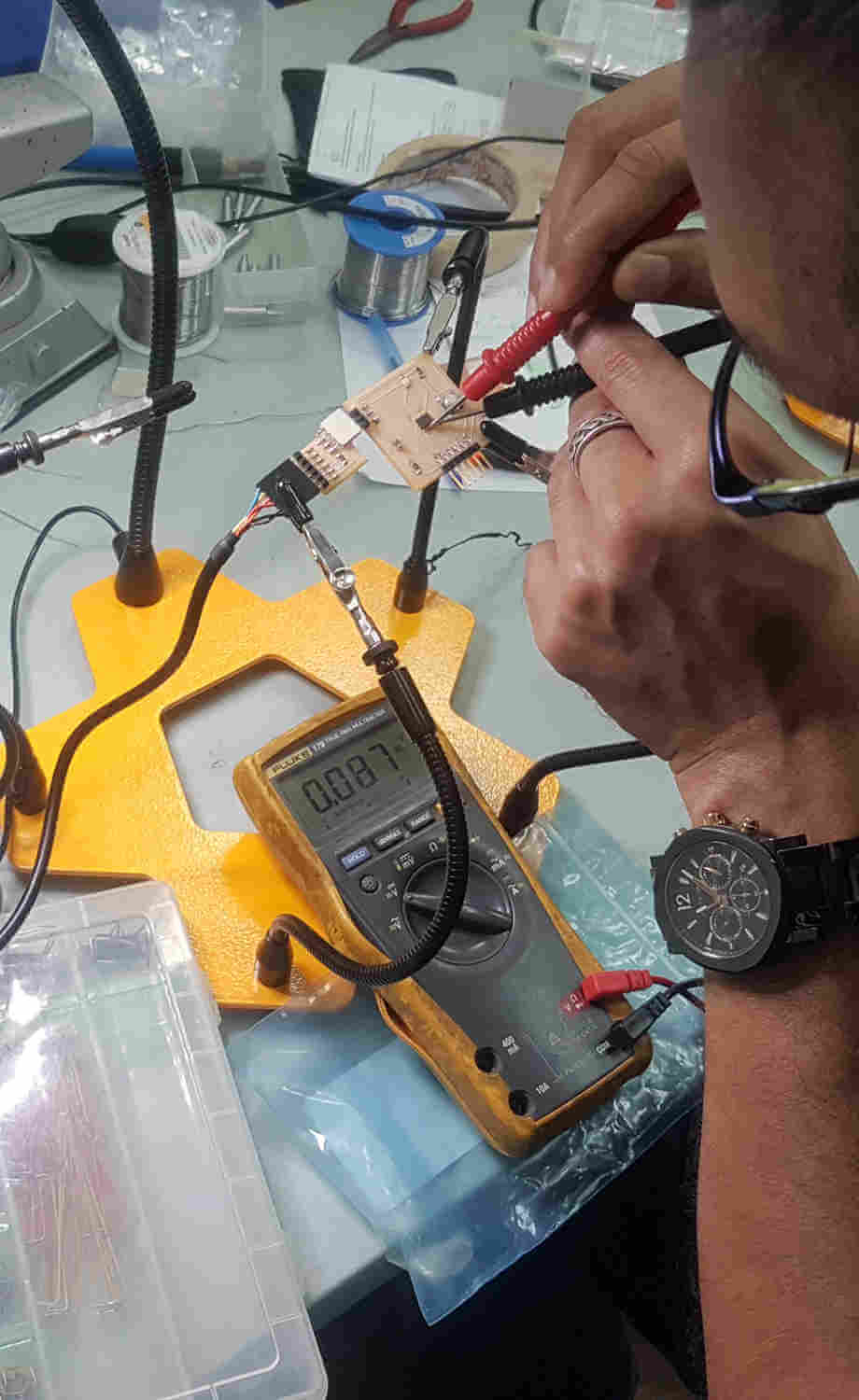
A digital multimeter is a test tool used to measure two or more electrical values—principally voltage (volts), current (amps) and resistance (ohms). It is a standard diagnostic tool for technicians in the electrical/electronic industries.
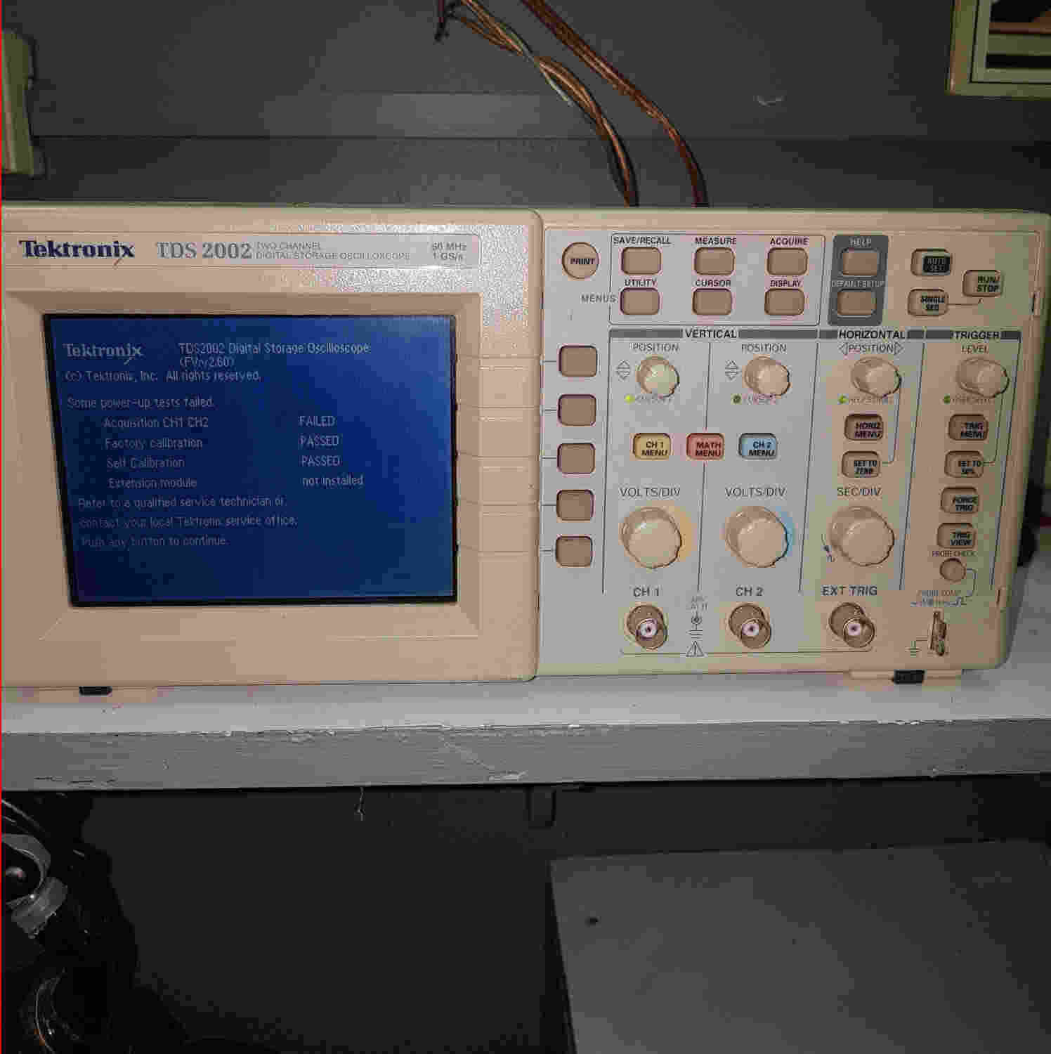
An oscilloscope is a device that allows you to see how voltage changes over time by displaying a waveform of electronic signals.
A signal generator is one of the most essential pieces of technology in electronics and communication. It is used to produce dierent types of signals and frequencies for a variety of purposes such as testing, troubleshooting, and designing.

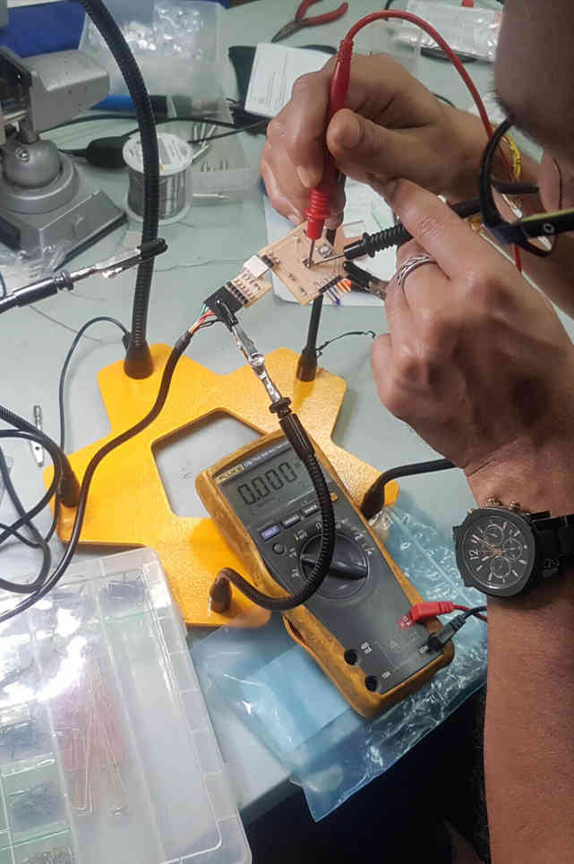
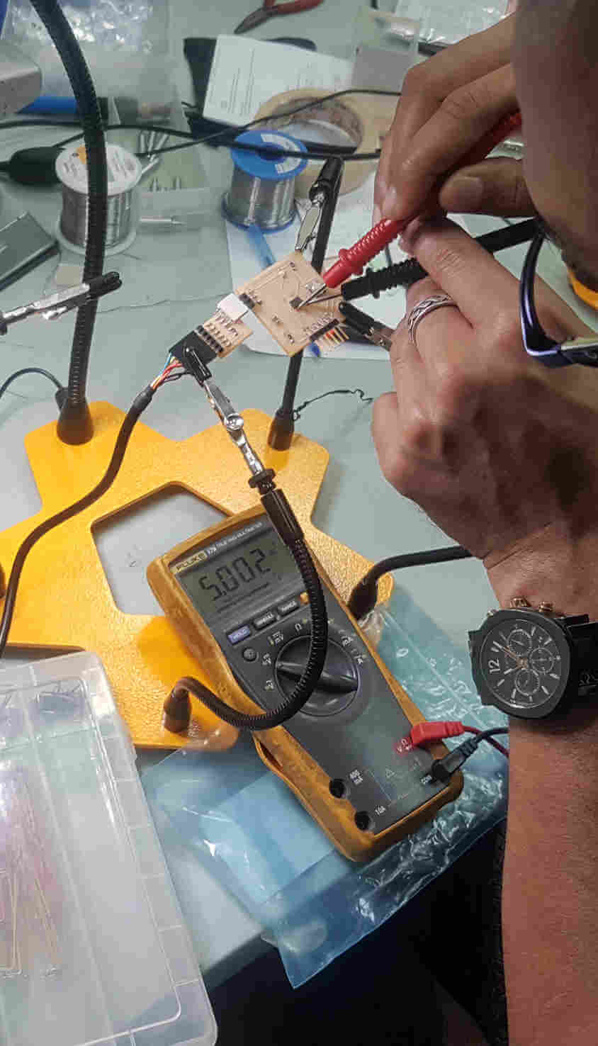
For this test we used one of the guys ATTiny 412 development board.
Programmer VCC-GND

PCB VCC-GND
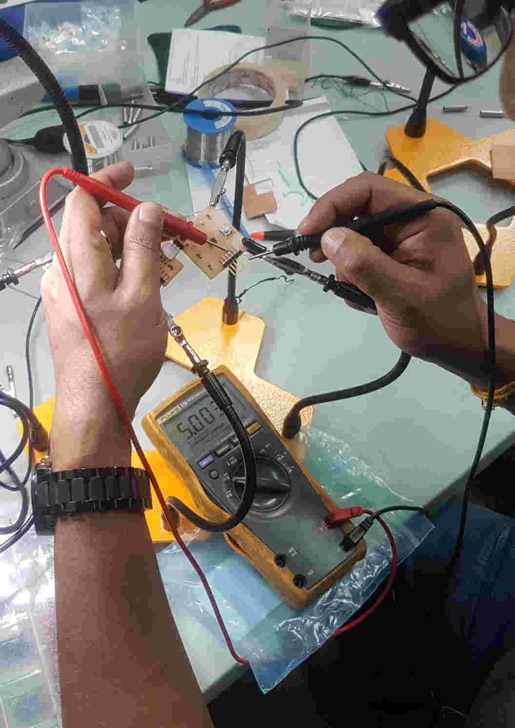
Chip pin1-pin8

Chip pin2-pin8
Chip pin3-pin8

Chip pin4-pin8
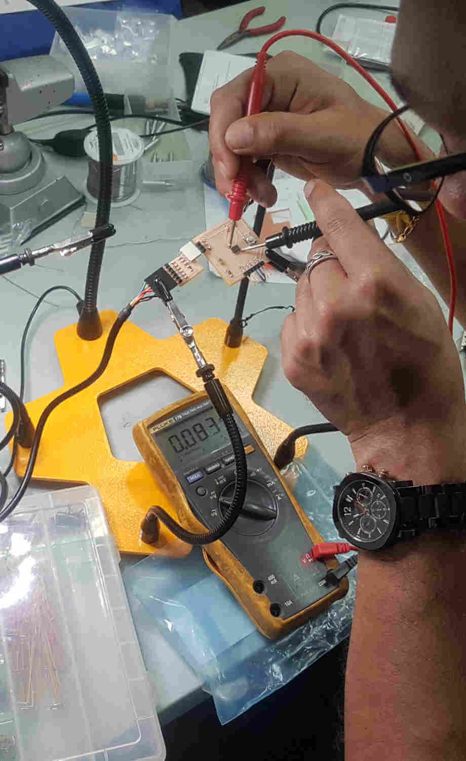
Chip pin5-pin8
Chip pin6-pin8
Chip pin7-pin8
A look at the wave signal when triggered by a switch.