16. Interface and application programming
For this week’s assignment, we looked at Interface & Application .This week looked at the following:
Group assignment:
-
Compare as many tool options as possible.
-
Document your work on the group work page and reflect on your individual page what you learned.
-
Group Project Link
Individual assignment:
- Write an application that interfaces a user with input and/or output device(s) on a board that you made.
Group Assignment Reflection
For this week’s assignment I got inspiration from another student from Fab Academy Nervene Bhagwandass.He utilized a bluetooth module, MIT’s App inventor and a micro -controller board he created.
1.Firstly ,I spent some time reviewing the useful youtube video which was used in the project .
HC-05 Bluethooth module with Arduino
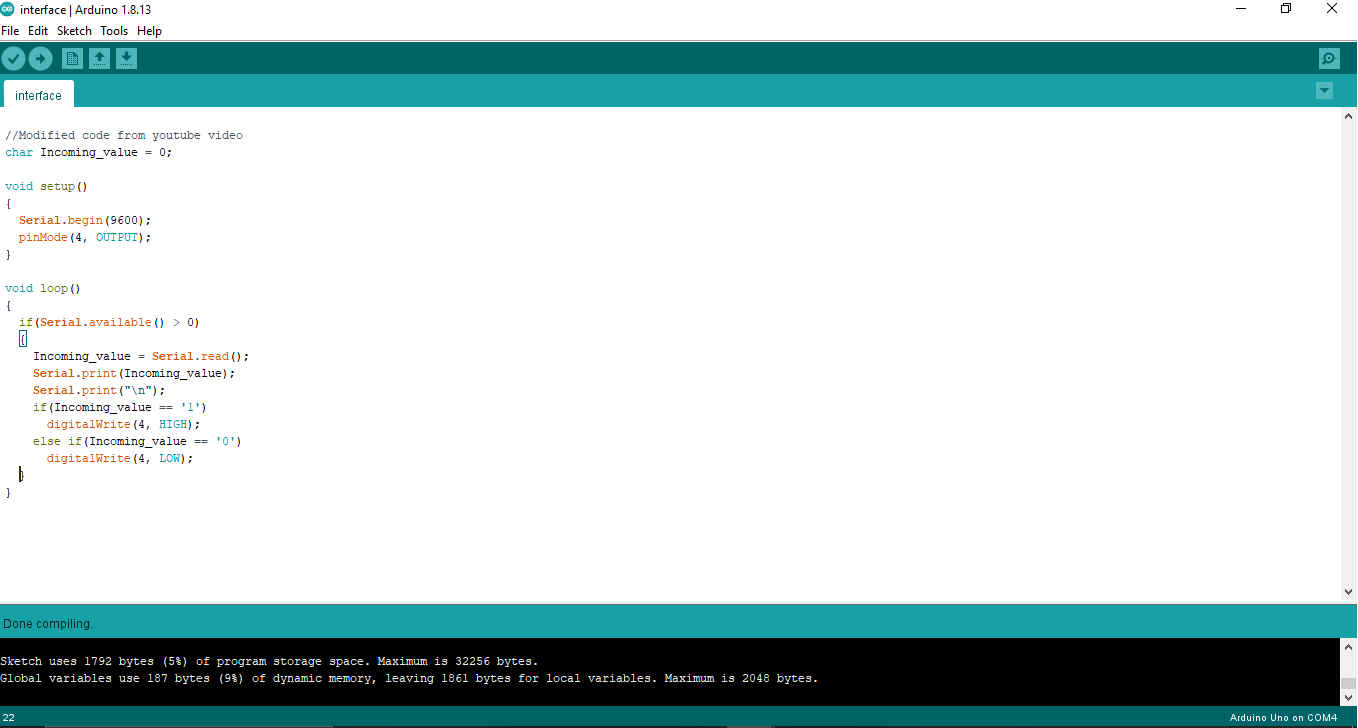
2.Then I spent some time modifying the code to suit the board I created for my Electronic Production.
//Modified code from youtube video
char Incoming_value = 0;

void setup()
{
  Serial.begin(9600);
  pinMode(4, OUTPUT);
}

void loop()
{
  if(Serial.available() > 0)
  {
    Incoming_value = Serial.read();
    Serial.print(Incoming_value);
    Serial.print("\n");
    if(Incoming_value == '1')
      digitalWrite(4, HIGH);
    else if(Incoming_value == '0')
      digitalWrite(4, LOW);
  }
}
3.Then I verified the code to ensure it had no errors.
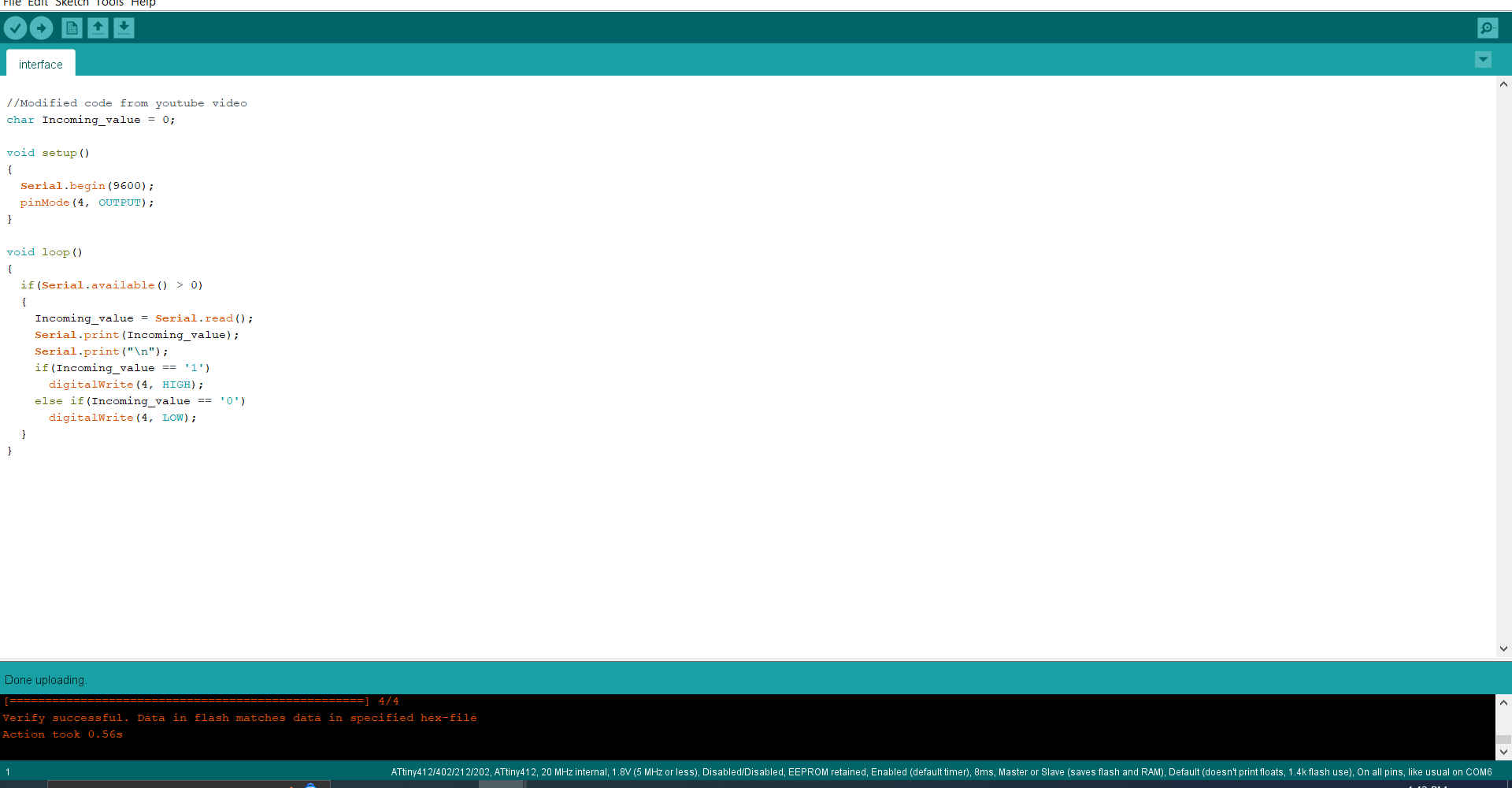
4.Then I uploaded the code to my micro-controller.
5.Then I went to theMIT App Inventor to create my app.
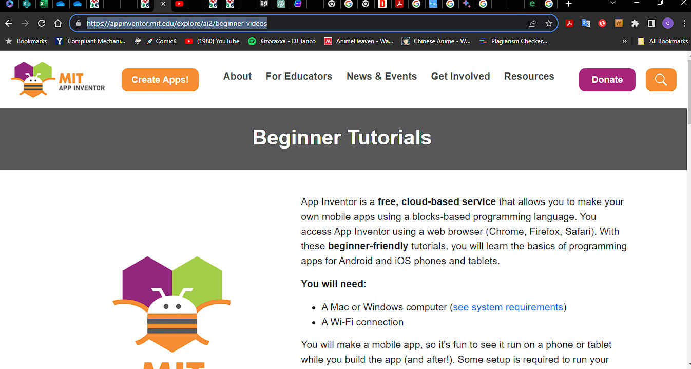
6.After I selected “create app” it asked me to login to my google account.
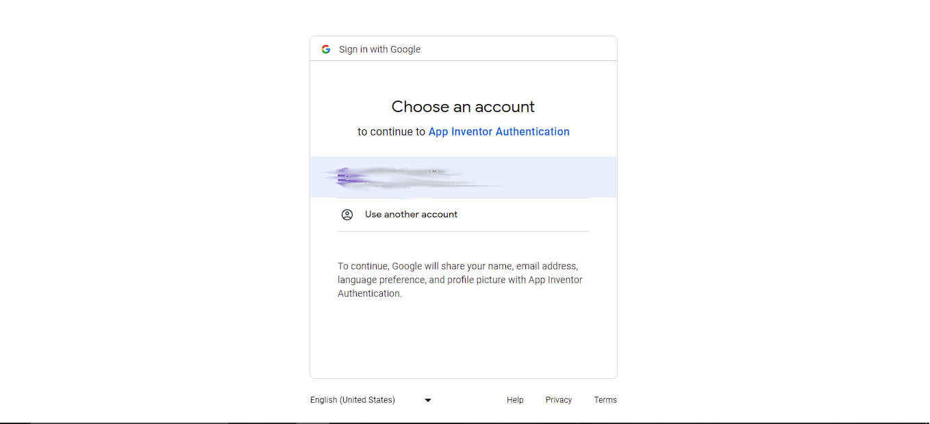
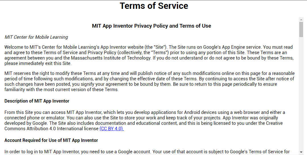
7.Then it brought up the “terms of service” document.
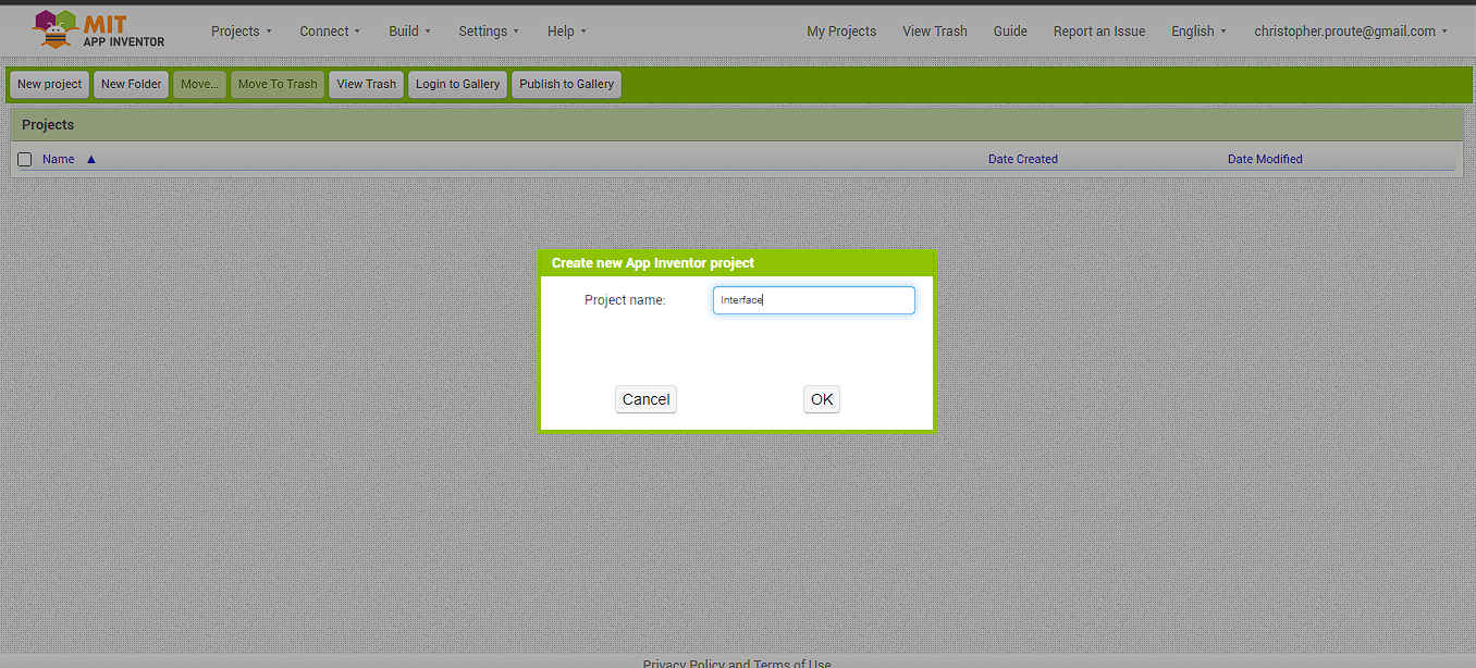
8.Then , while in the app I selected “New project ” and name the project.
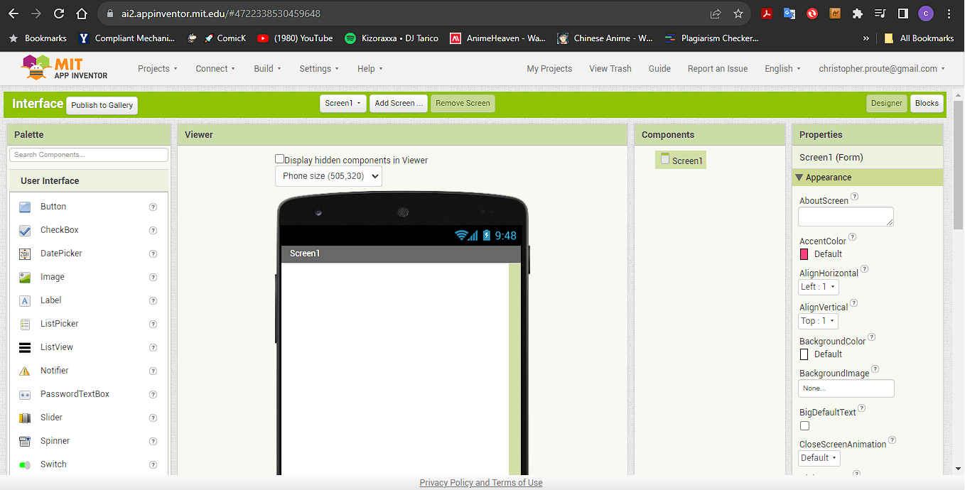
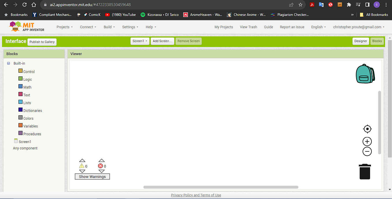
9.This brings up the app work area where you can either view “designer” or “block”.
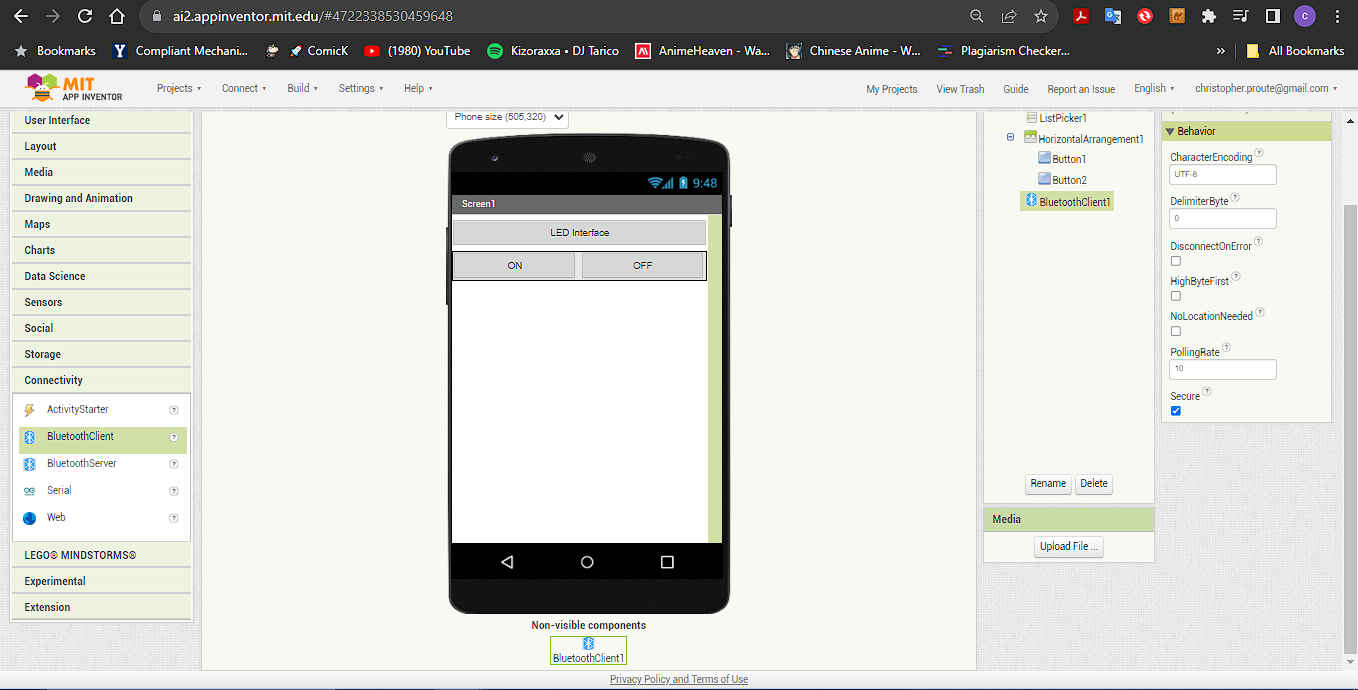
10.Then I added a list picker by left clicking and dragging it to screen area.
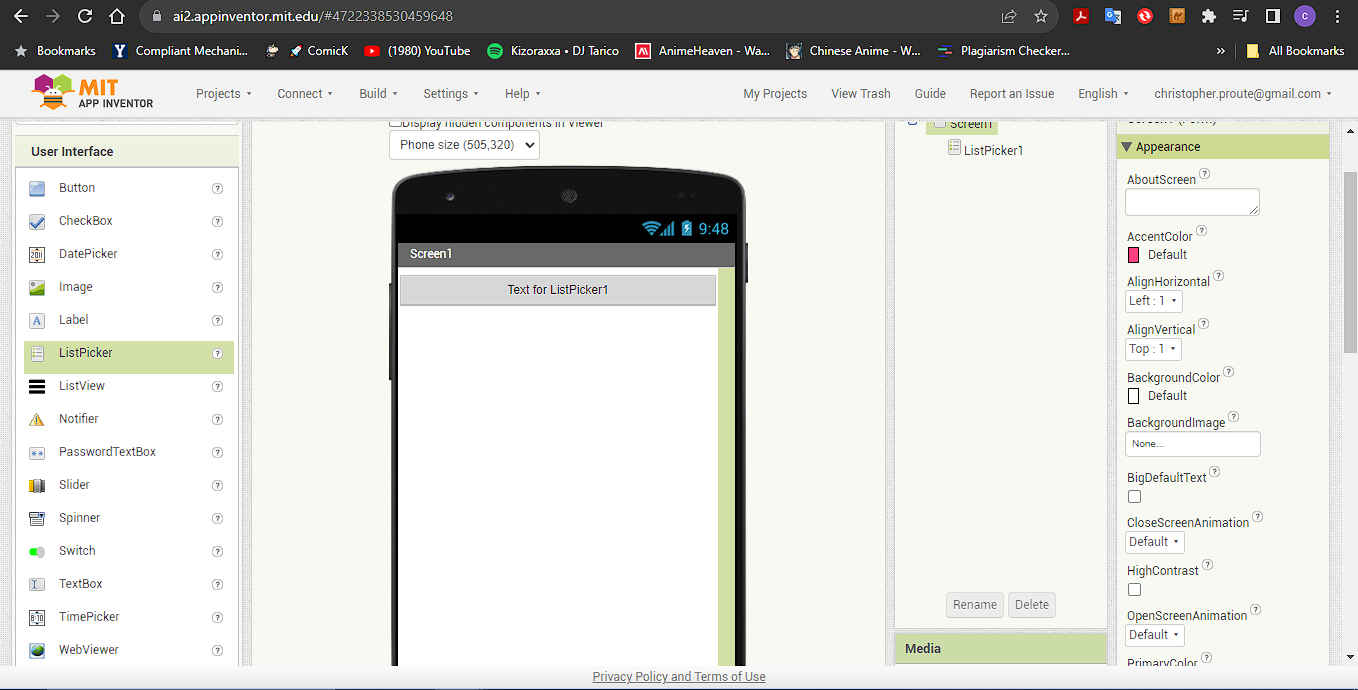
NB. There are option on the right side to edit the objects you have selected
11.I then added a custom name to my the list picker.
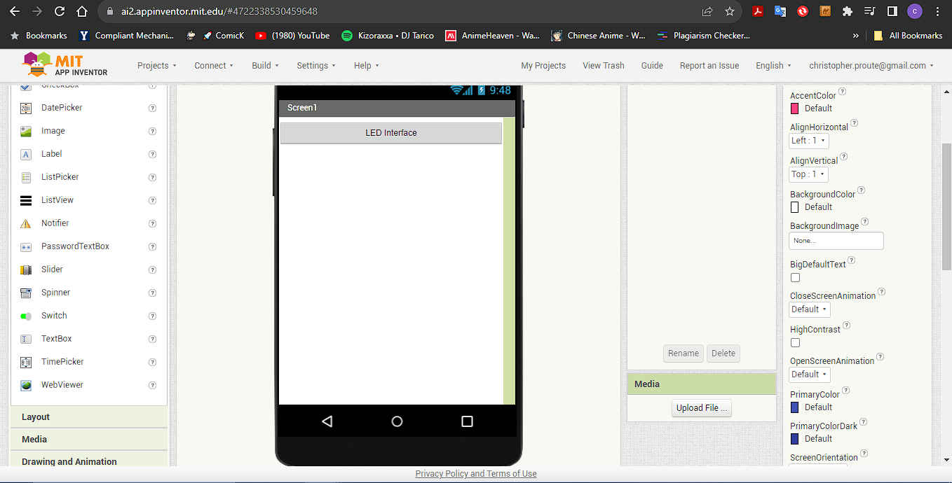
12.Then in the layout tab I added “horizontal arrangement” to my screen.
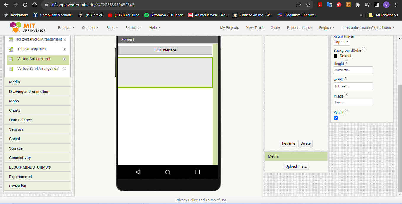 NB. Select fill parent causes the element to fill the screen.
13.Then under user interface added two buttons to turn bluetooth on and off.

14.Then under “connectivity I added the bluetooth client
15.After this I changed to the block view by select the word blocks in the top right corner.
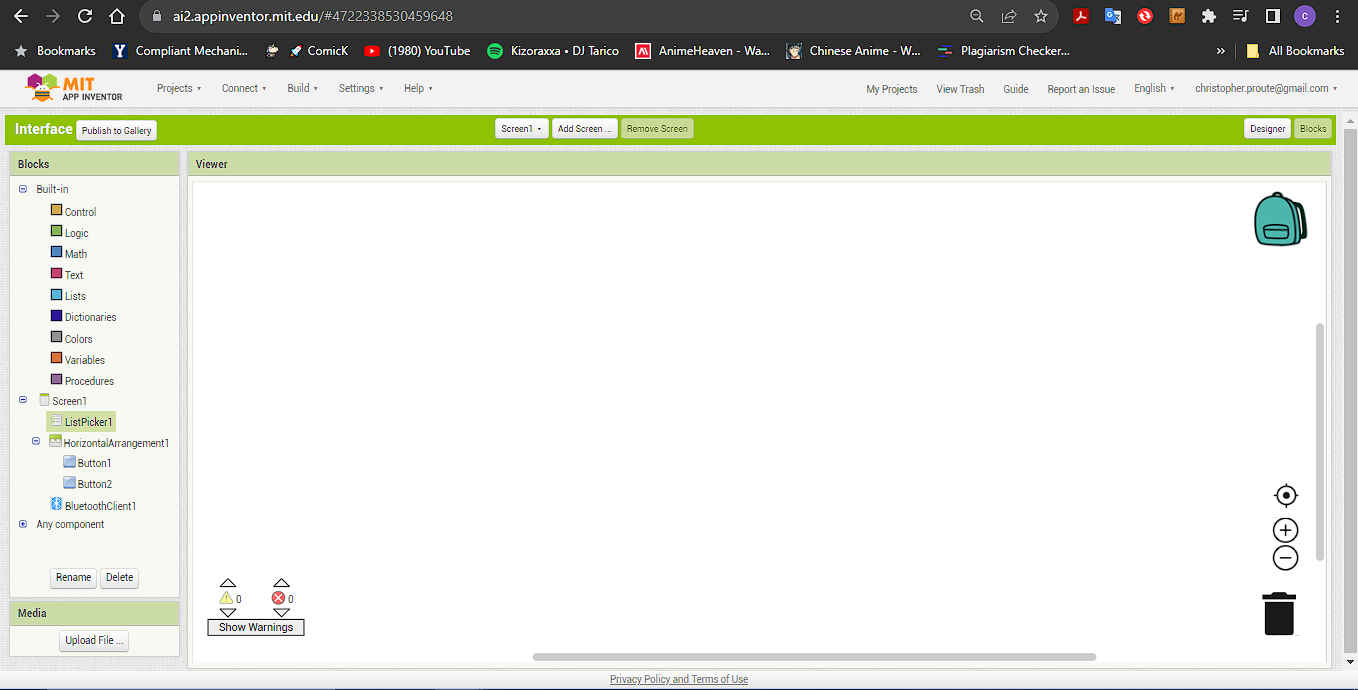
16.Then under screen I brought two list picker elements ( before and after ) by clicking on the list picker name.
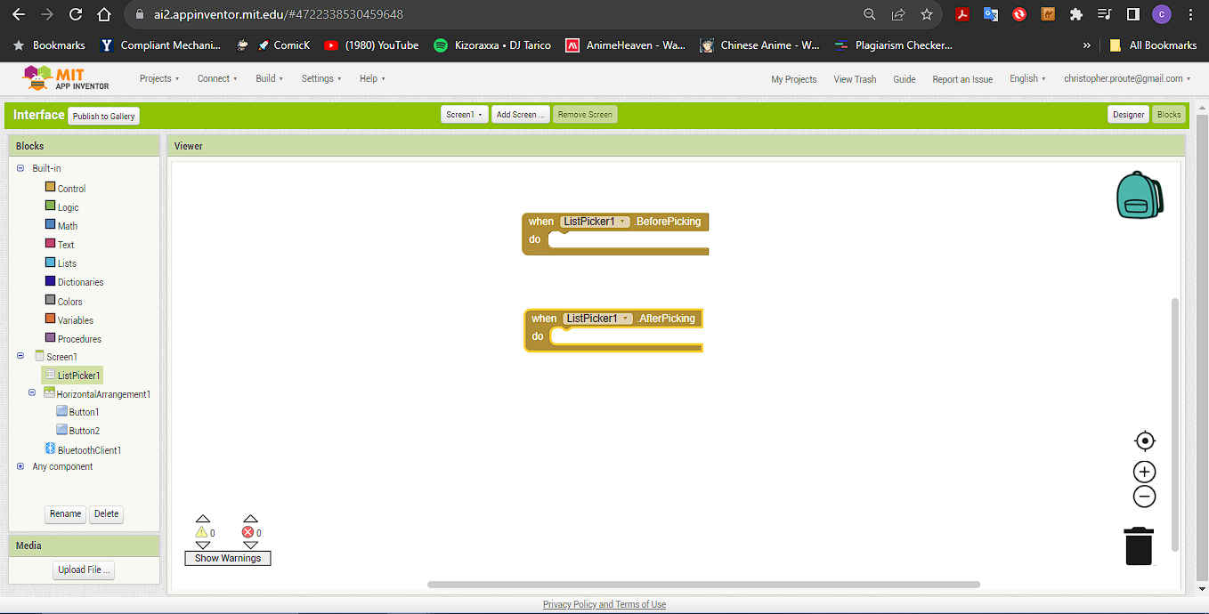
NB. If you have used scratch it work similar.
17.Then under list picker I brought in the set to element and added the bluetooth client name by selecting bluetooth client.
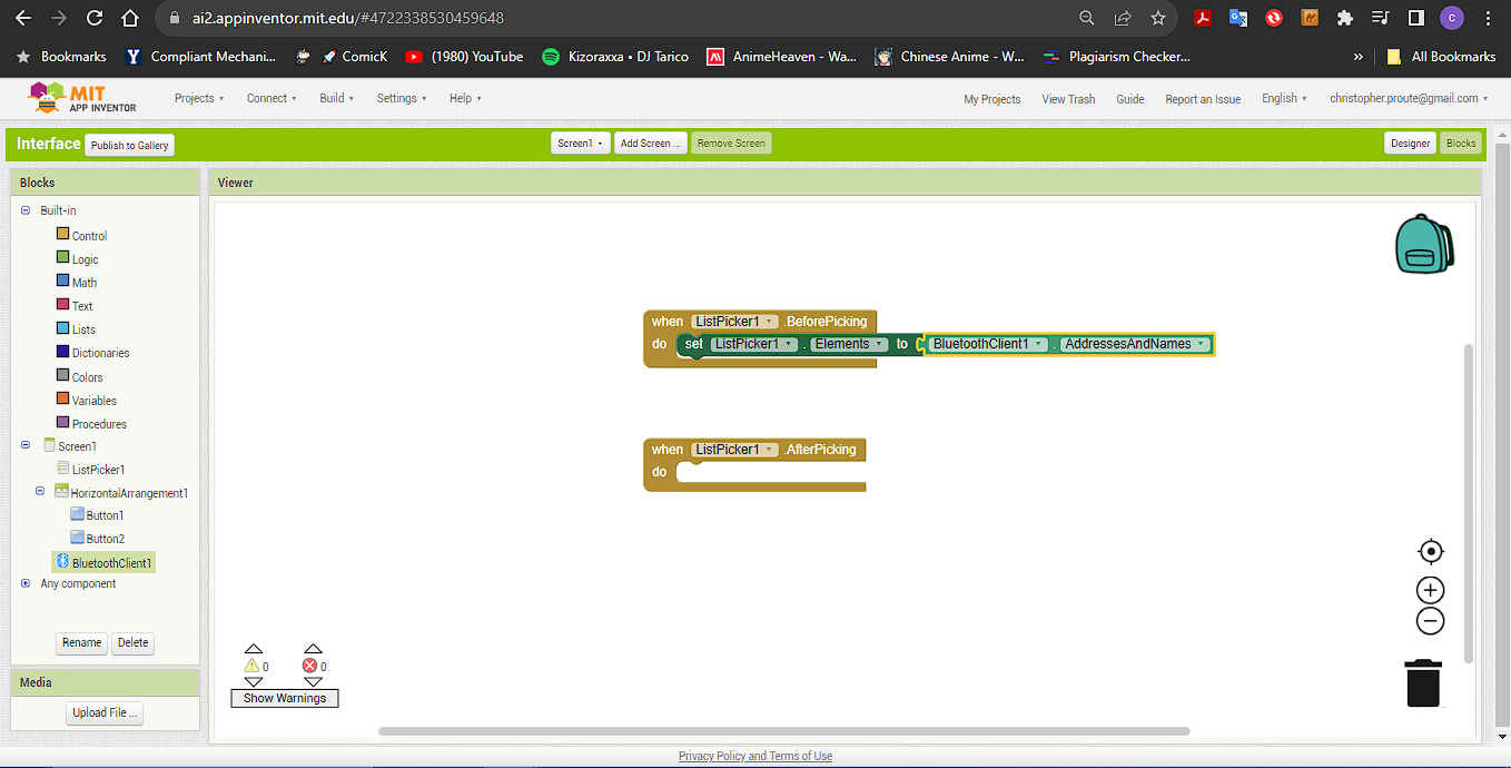
18.Then under list picker I brought in the set selection to and added the bluetooth client connect by selecting bluetooth client.
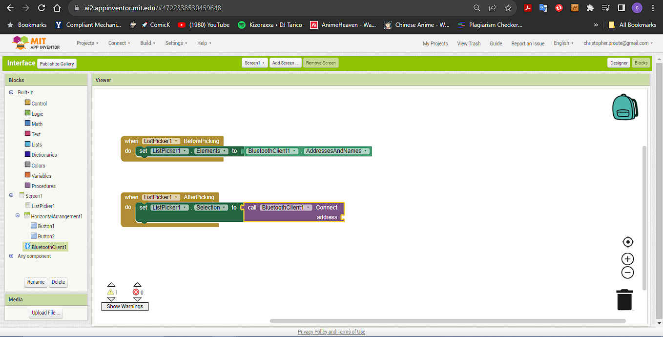
NB. Show a list of connected bluetooth devices.
19.Then under list picker I brought in a list picker selection and list picker to text . I also included the text “The eagle has landed”
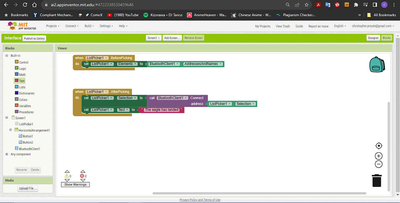
NB. This will show the text message when connected
20.Then under button I brought in a button 1 & 2. Then added the bluetooth send to text (from bluetooth ) with a unique text (from text) to each button. This will send the signal to the micro-controller to turn the LED on or off.
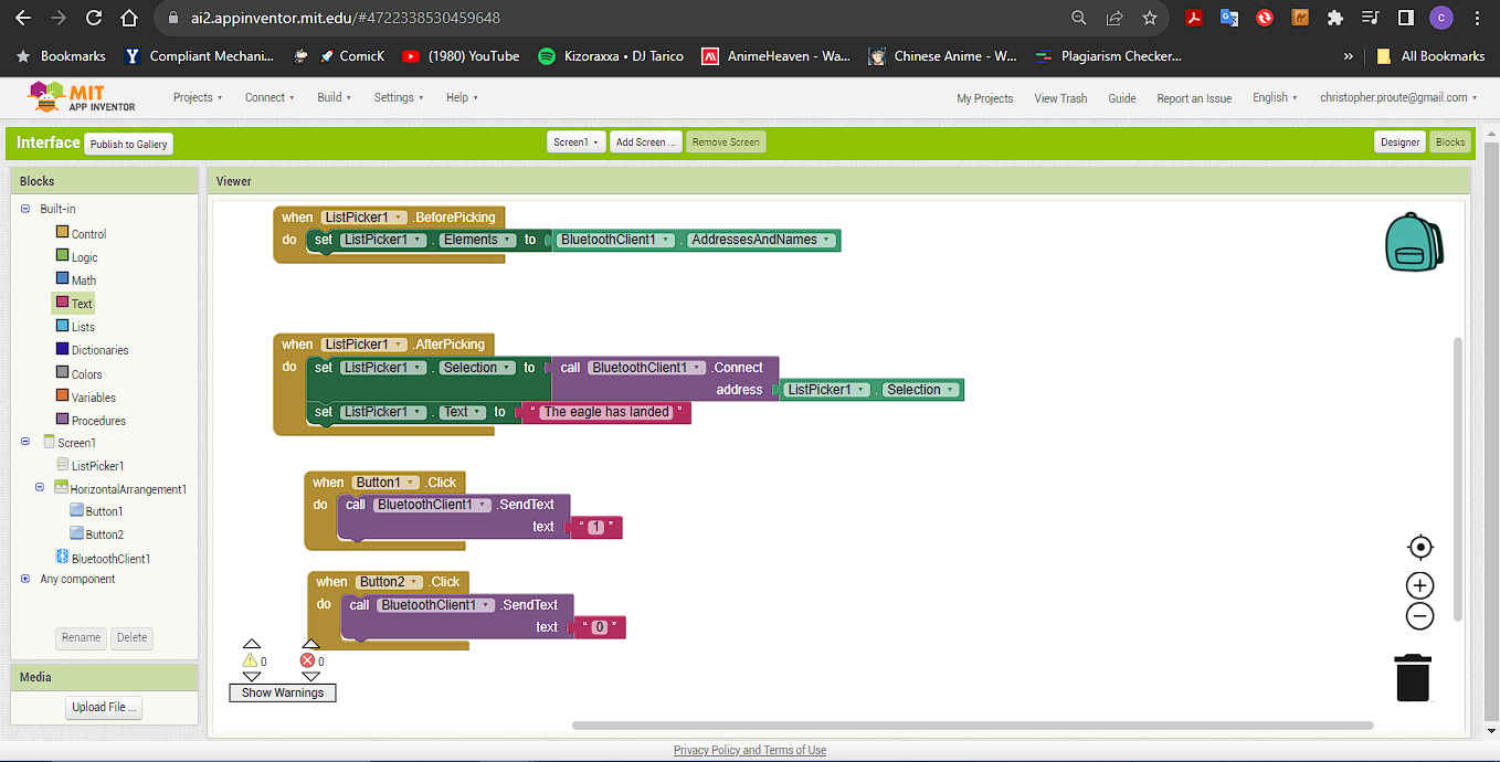
NB.Rather than dragging the same code to the screen you can duplicate by right clicking and element and selecting duplicate
21.Then in order to download my app I had to install the MIT AI companion app.

22.Then in order to download my app I had to install the MIT AI companion app and open it.
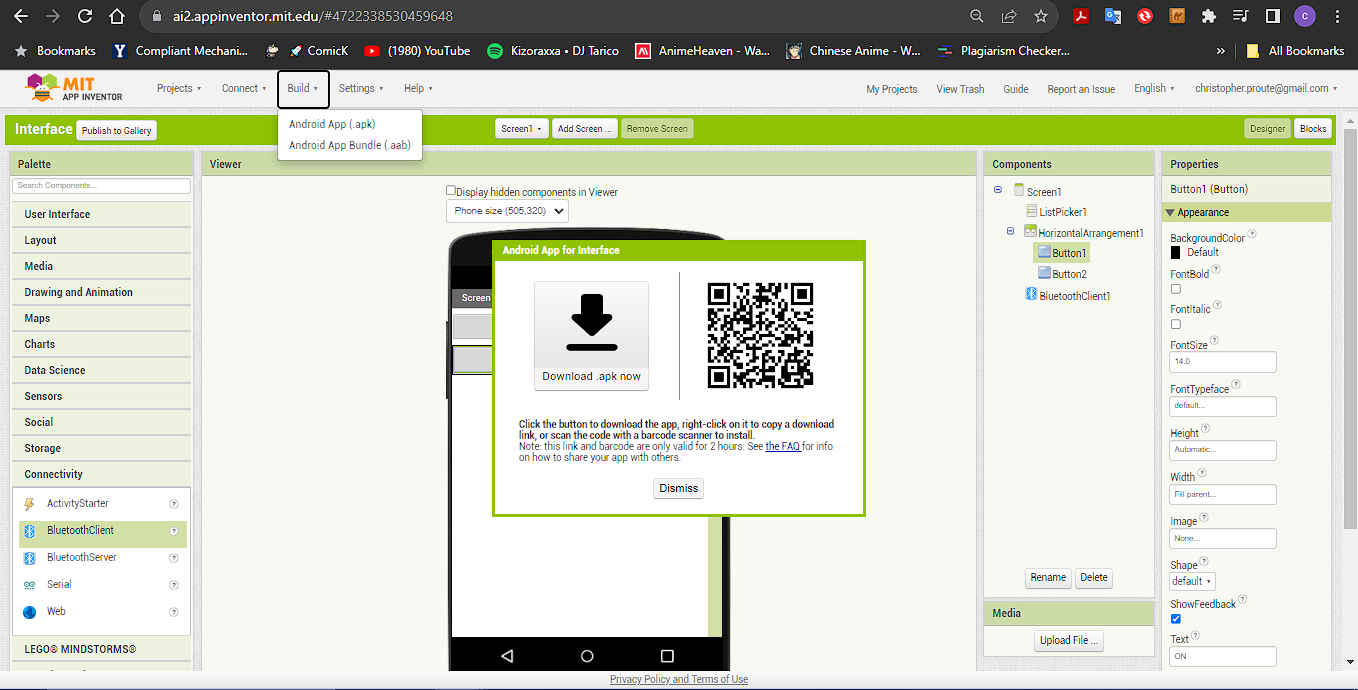
24.Then select the build tap and choose the apk option it will take a few minutes to complile. Then it will ask if you want to download or use a QR code.

25.After the the software was installed I powered on my micro-controller board. Then turned my bluetooth on and connected it to the bluetooth module.


- Unfortunately, this did not work , so I had to look at another solution using the resources I had available.


Interface Take 2
For my second look at this assignment I drew inspiration from Vilhjalmur Magnusson aka Villi a Fab Academy student from 2016 and he drew inspiration from another Fab Academy student from 2015 Roy Livne. Their projects looked at creating a display using a phototransistor. This interested me as I was also using a phototransistor in my final project.
1.The first thing I did was review a ttutorial on creating a connection between arduino and the processing app.
2.The first thing I did was download the processing app and opened it.
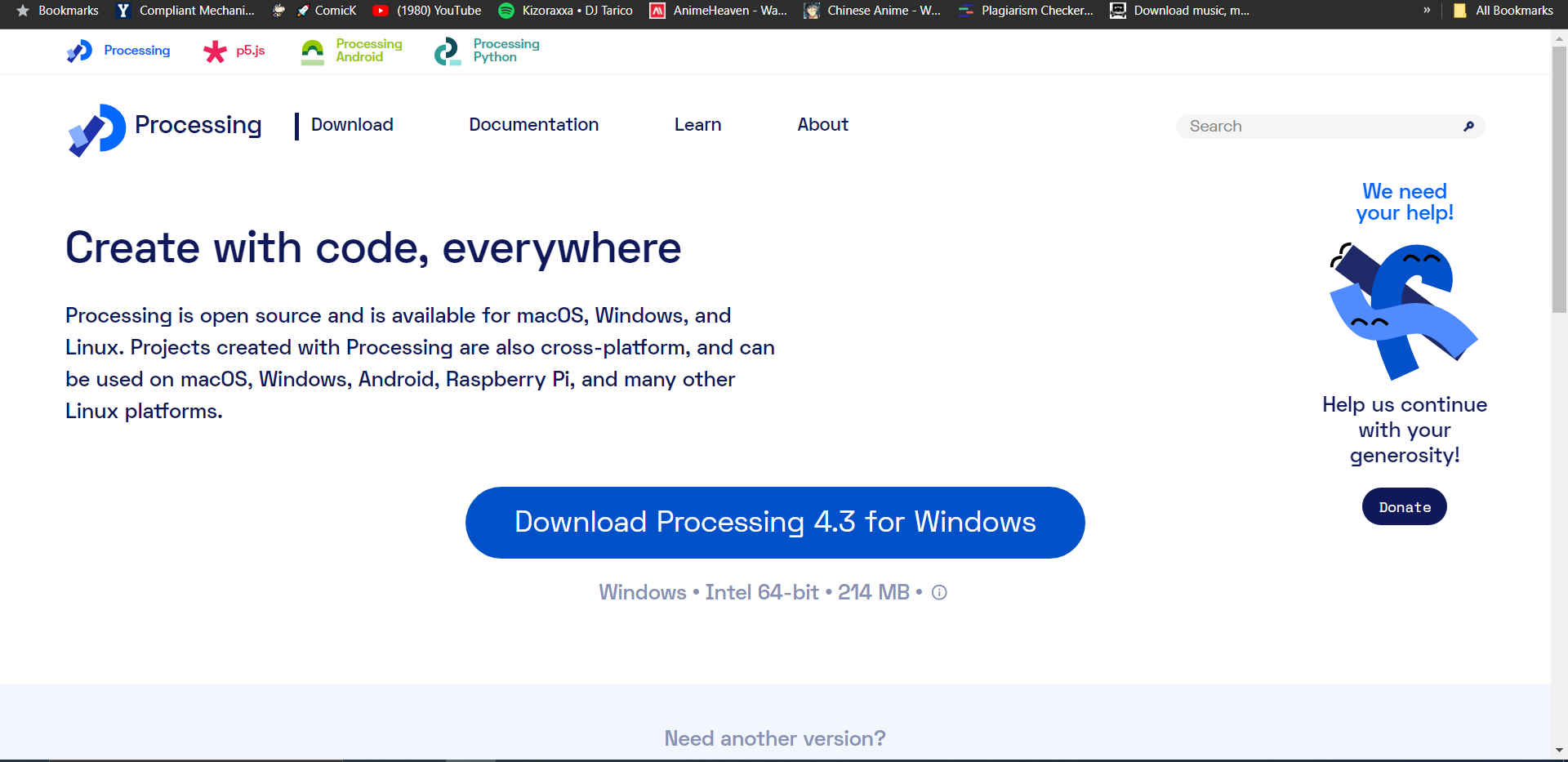
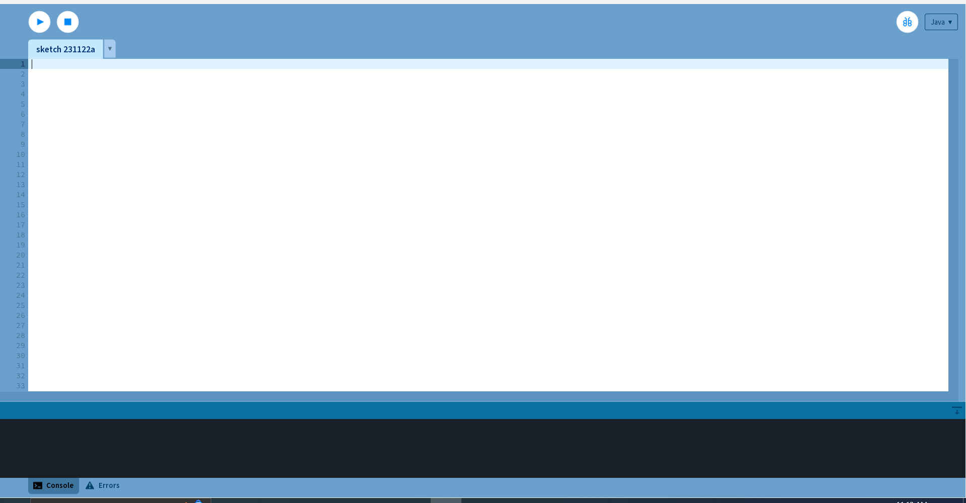
NB. This app was used along with the Arduino Ide to create the interface.
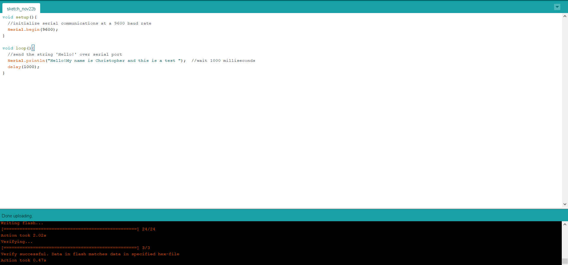
3.Then I followed the steps outlined in 1 above. I created the Arduino Code first and made a change in the print statement, delay and baud rate.
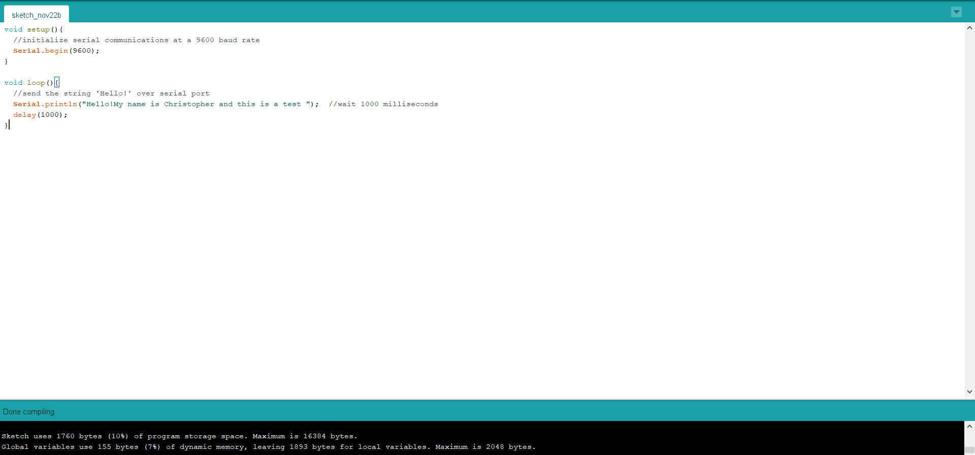
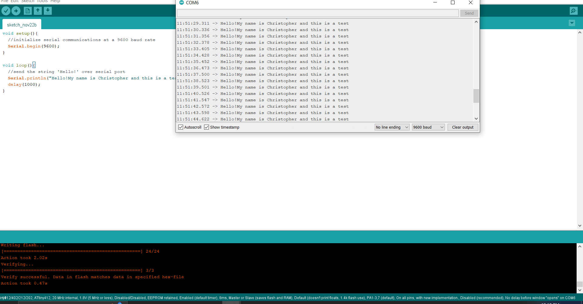
4.Then I tested the code with the PCB to ensure it was working properly.
5.Then I placed the code in in the processing app. I also changed the port name to suit my computer and the baud rate to match the arduino code.
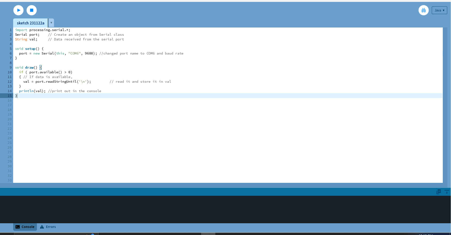
6.After communication was secured I tried implementing the code from Villi. From the orignal code the only variable that would have changed would be the port name to match my computer.
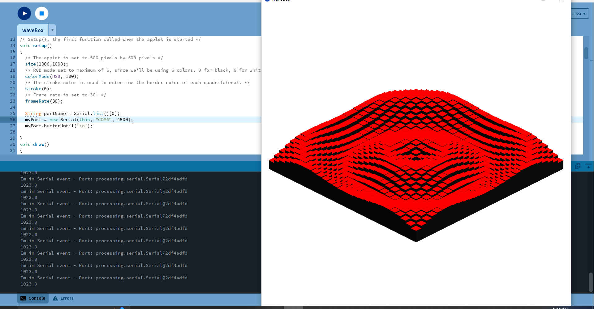
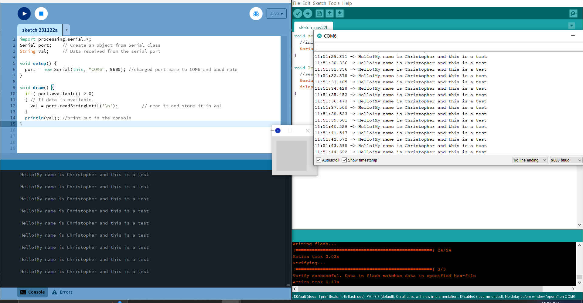
7.Then I made changes to the code to see what affect it would have on the interface.
Villi Processing configured for my port