5. Electronics production
For this week’s assignment, we looked at the various aspects of electronics production. The following was required for the week:
Group Assignment:
-
Characterize the design rules for your in-house PCB production process: document feeds, speeds, plunge rate, depth of cut (traces and outline) and tooling.
-
Document your work to the group work page and reflect on your individual page what you learned
Individual Assiignment:
- Make and test the development board that you designed to interact and communicate with an embedded microcontroller.
As this assignement was related to the assignment from the electronics design week I continued from where I ended during that week Click here
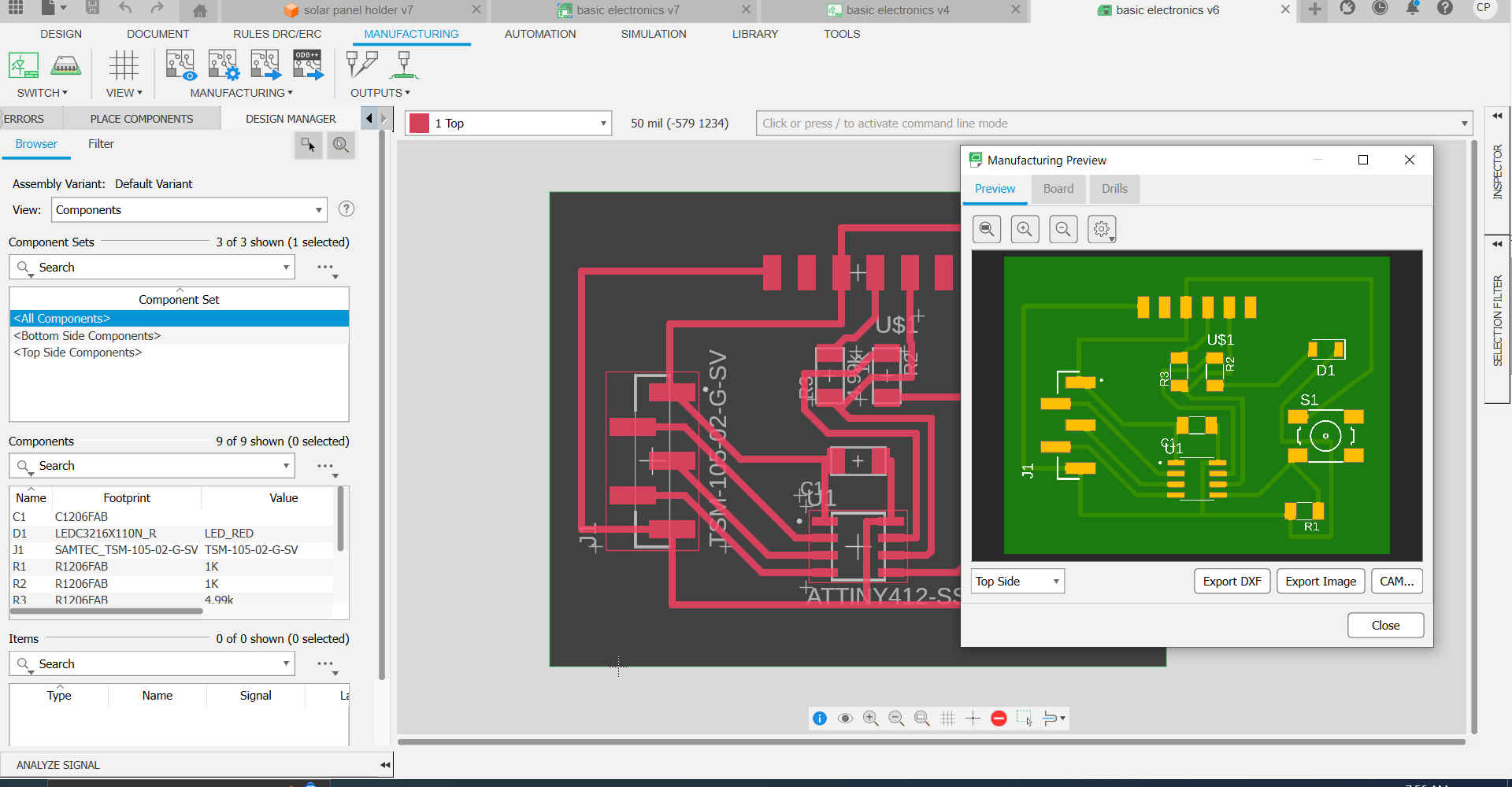
1.First, I went to the location of my 2D PCB which I previously designed and selected manufacturing.
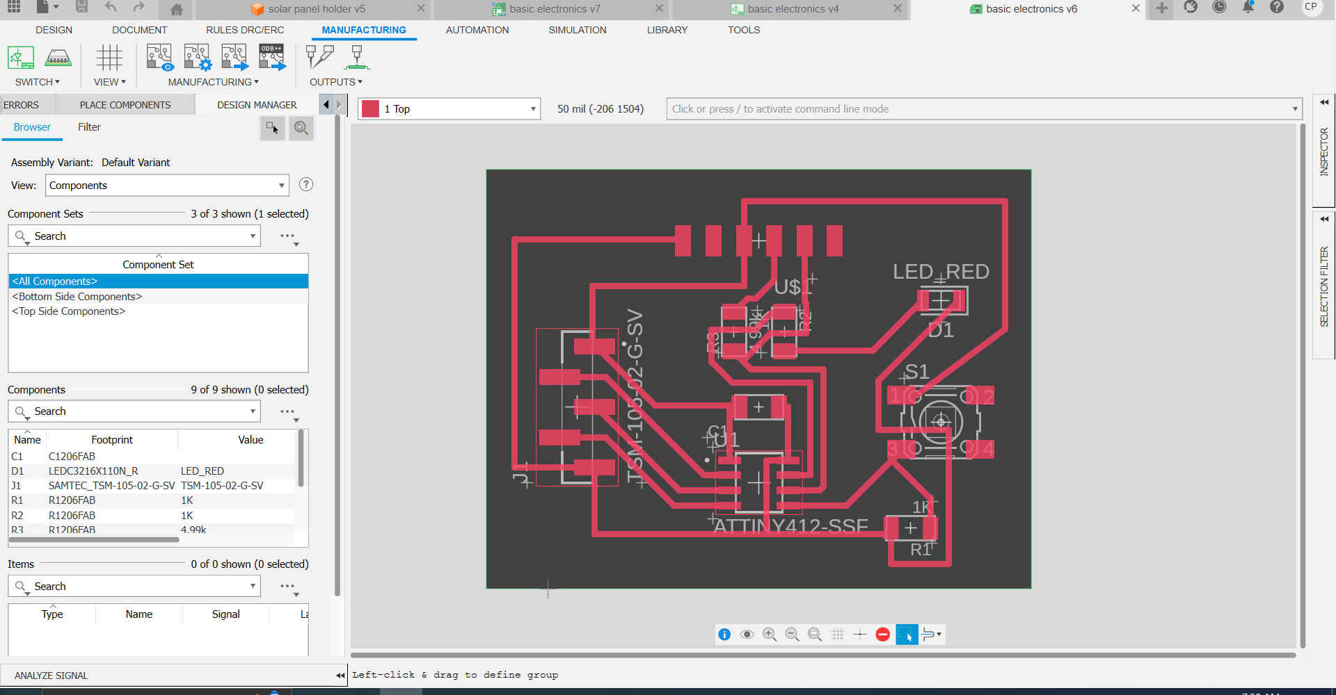
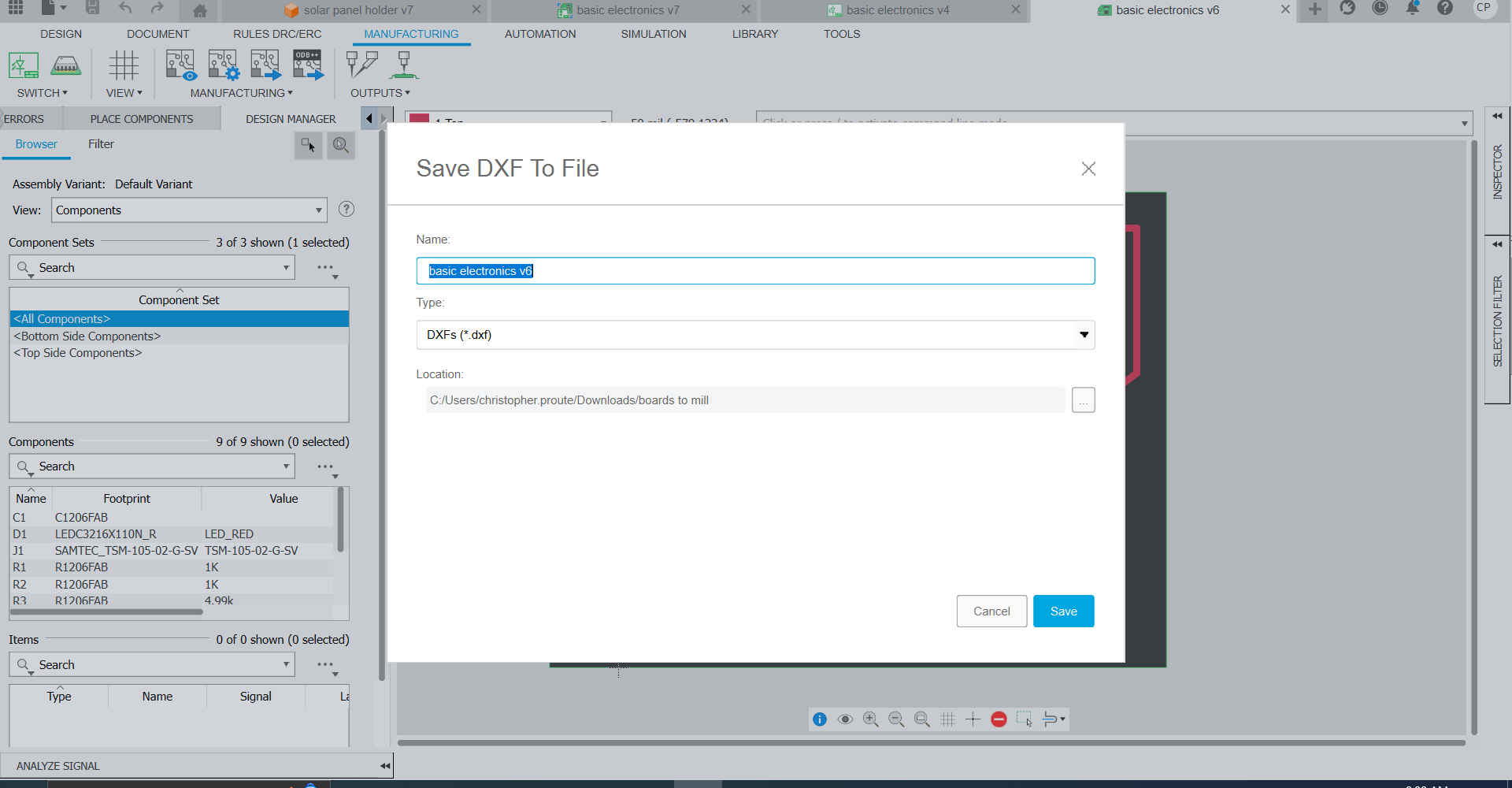
2.Then I selected CAM Preview to view the different layers of the PCB and exported the toplayeras a DXF.
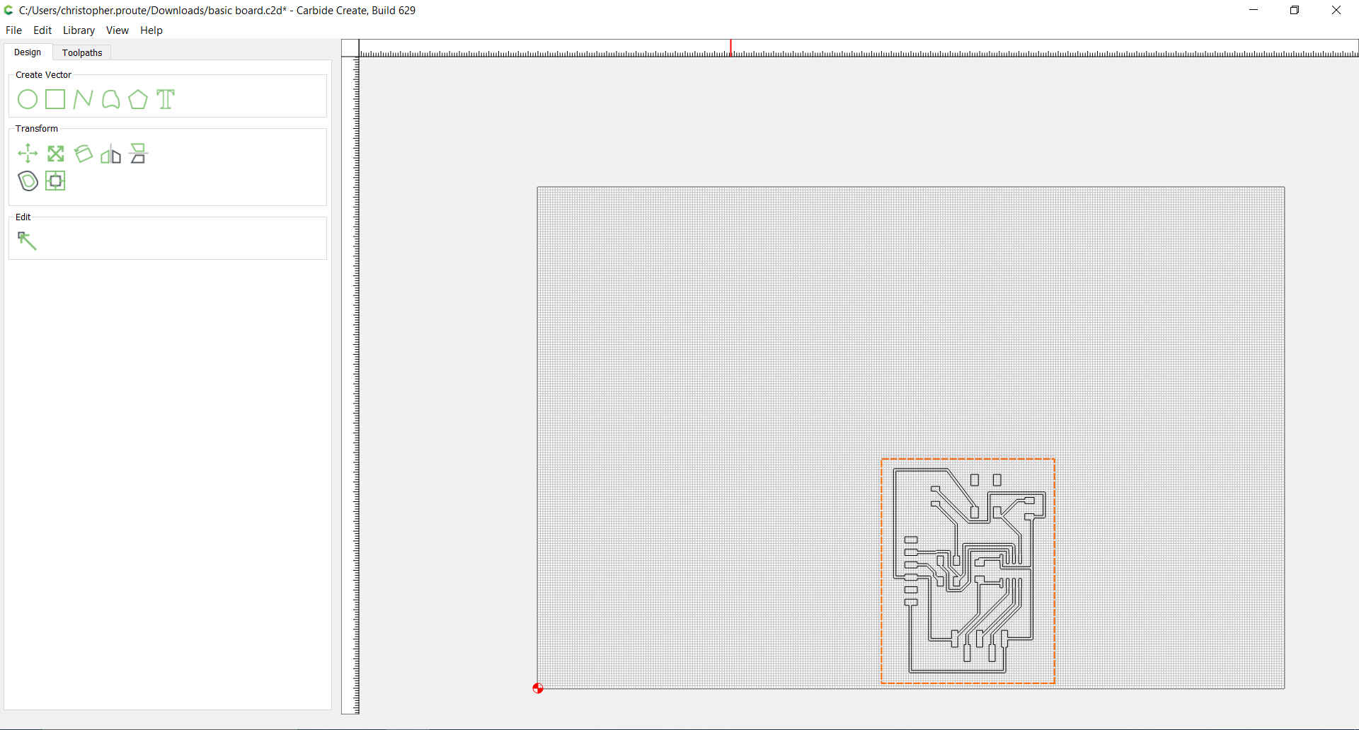
3.Then I opened the file in Carbide Create software which runs our precision mill and set the dimensions for the board I would be milling.
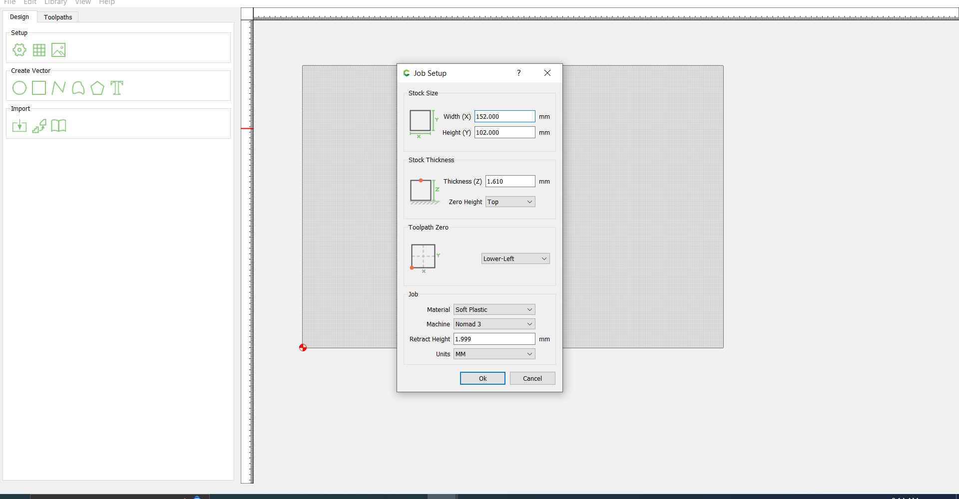
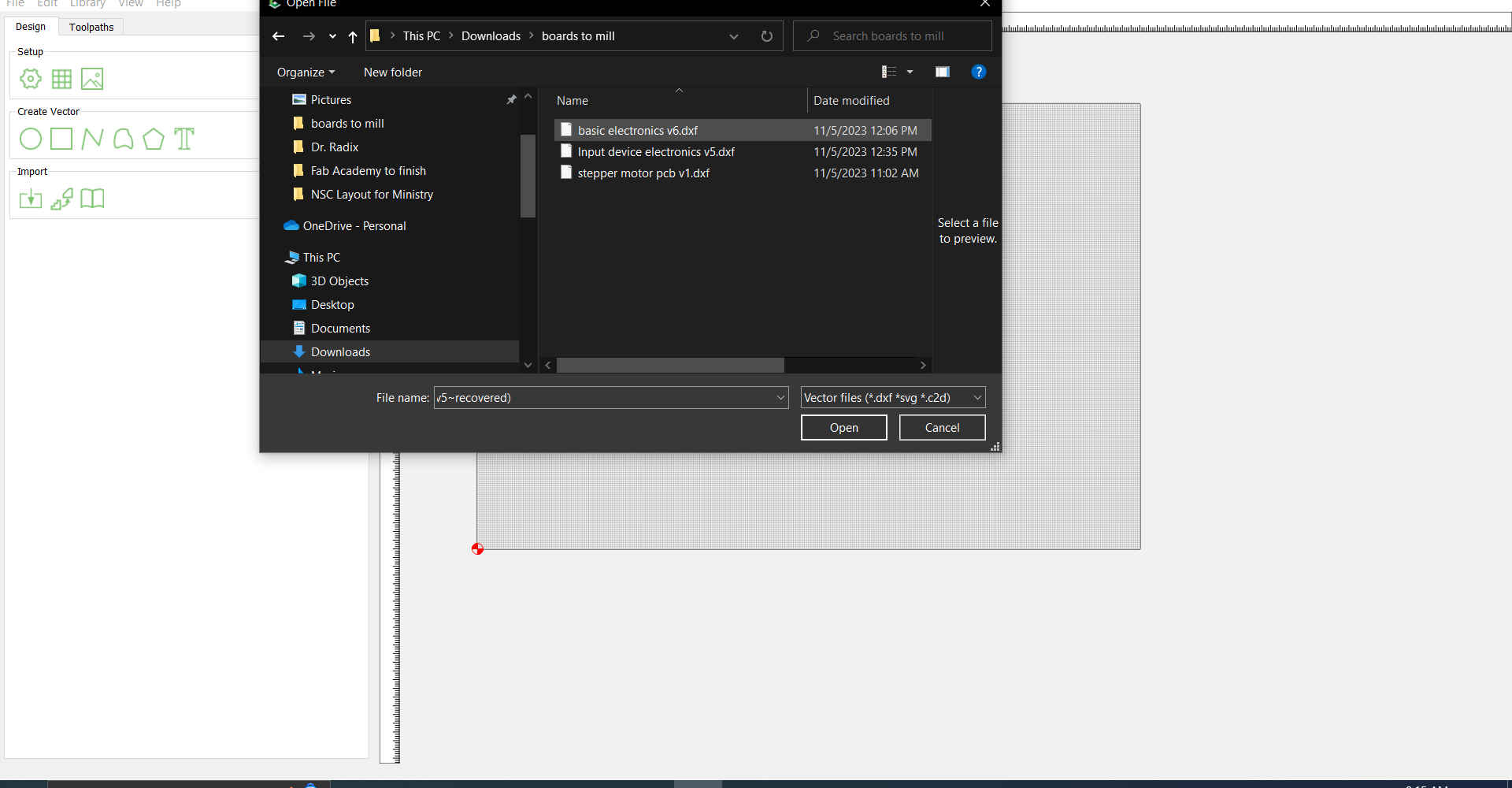
4.Then I imported the PCB file and placed it in a desired location.
Note. Ensure that the appropriate units are selected. The units can be changed by selecting the gear icon.
5.Then I selected the entire image,selected toolpaths and select pocket.
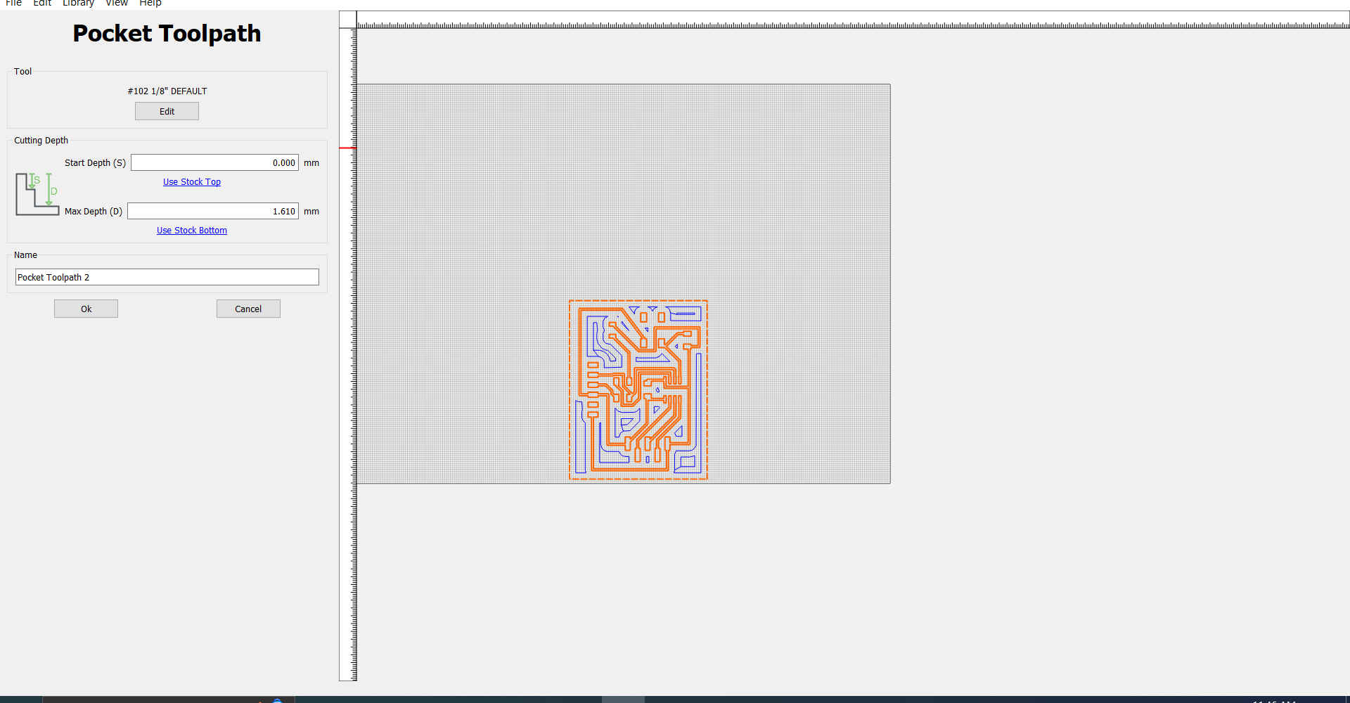
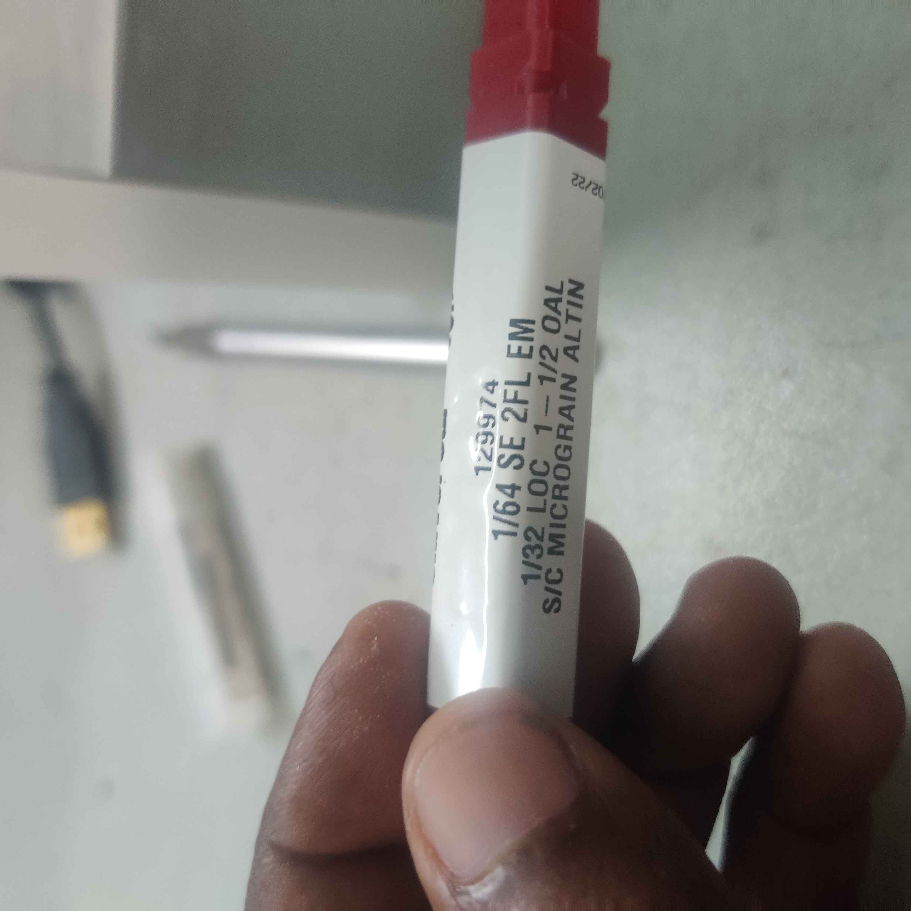
6.Then select tool was chosen and the preferred job settings chosen, which included the type of machine, bit, material, and process being carried out.
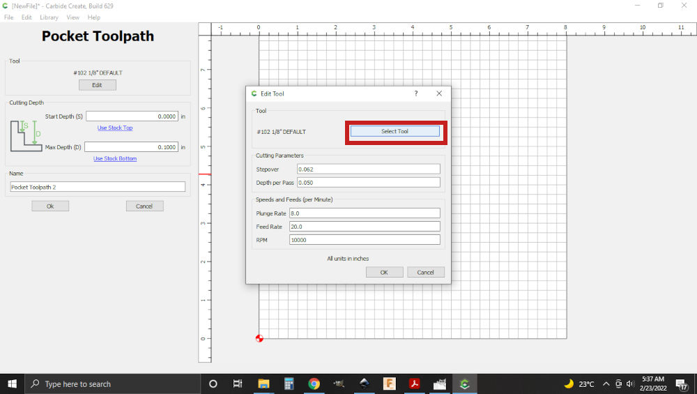
Note. A new profile was created because the bit will be used as an end mill rather than an engraver.
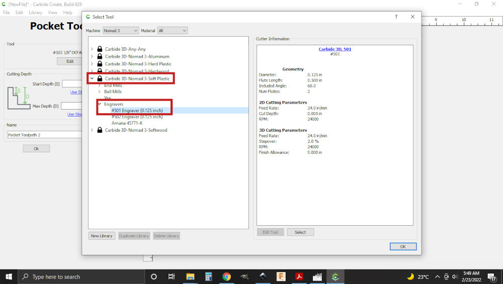
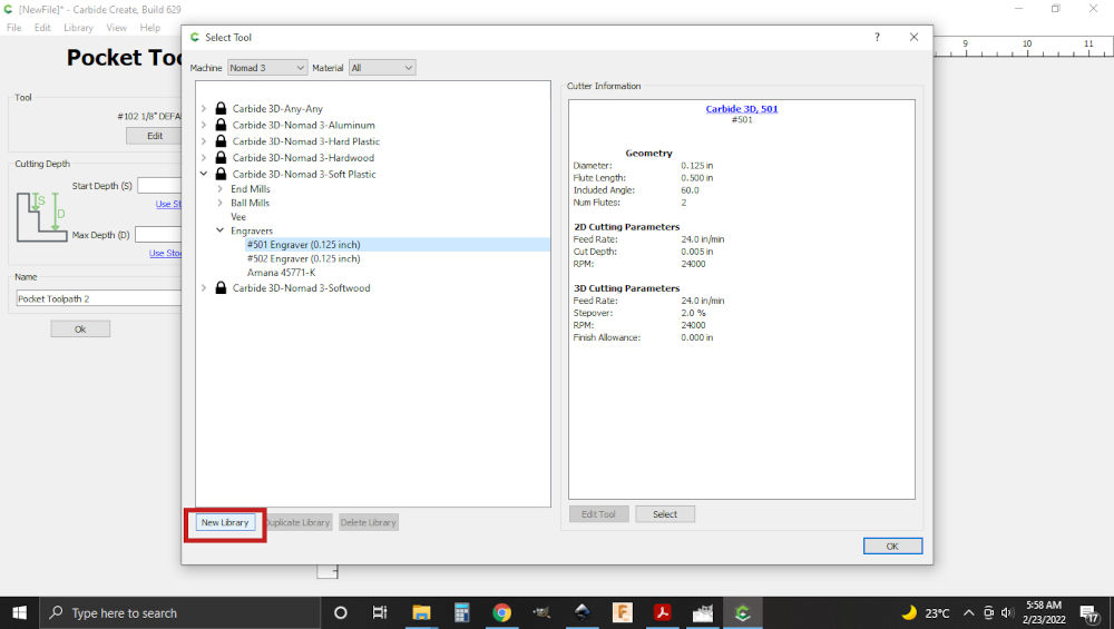
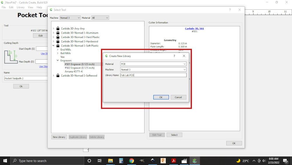
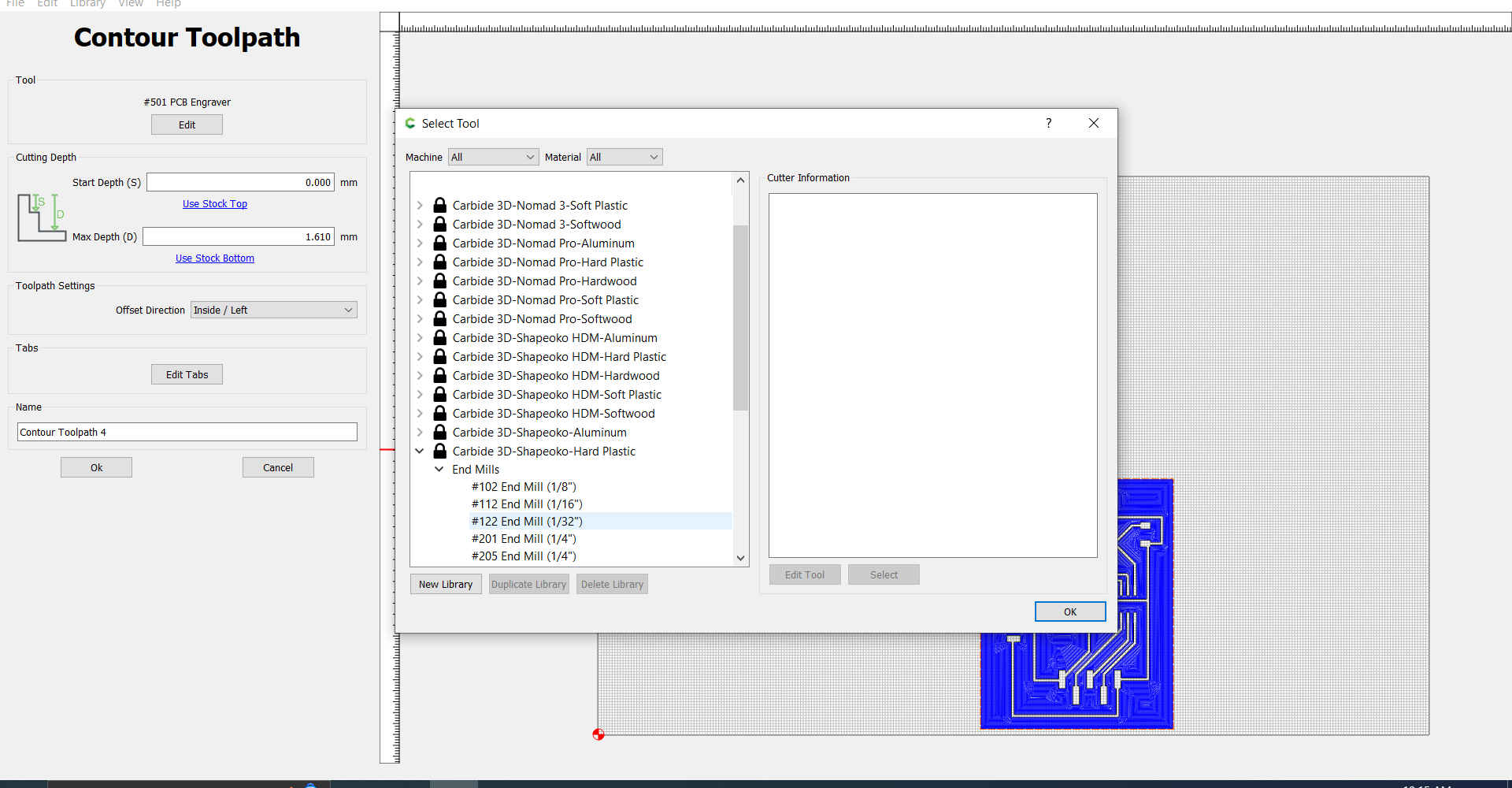
7.Then new library was selected to create a new category.
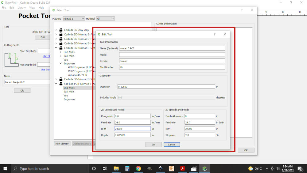
8.Then in the new category that was created, I right clicked on endmill, chose new tool, endmill and selected inch. At this point the information from the 501 bit was added.
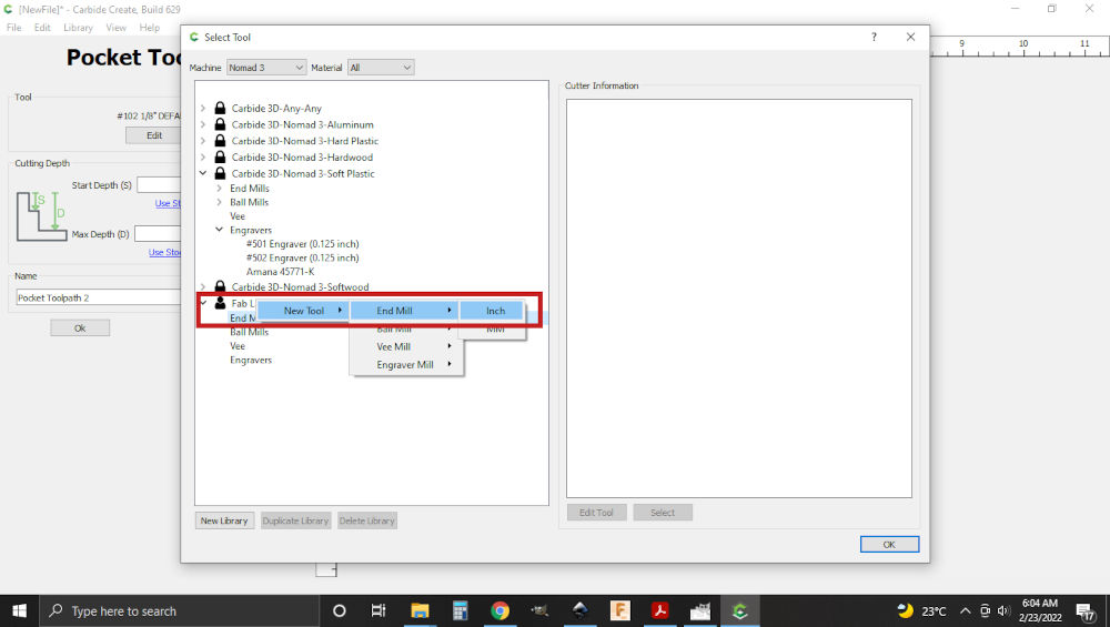
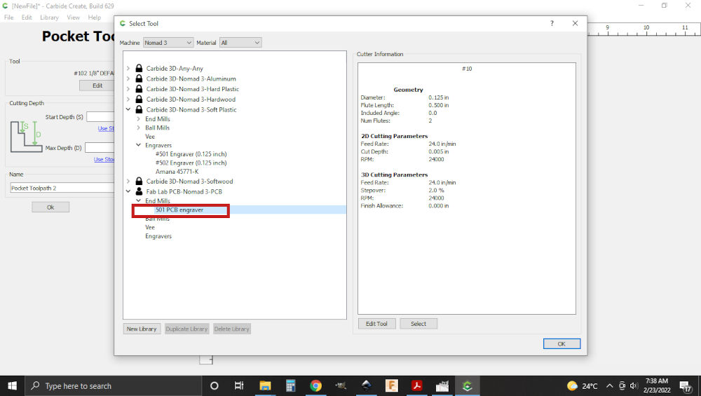
Note. When you select the new category created, there will be a new option under the endmill
9.Then as I created the required tool , I selected it as the required tool.
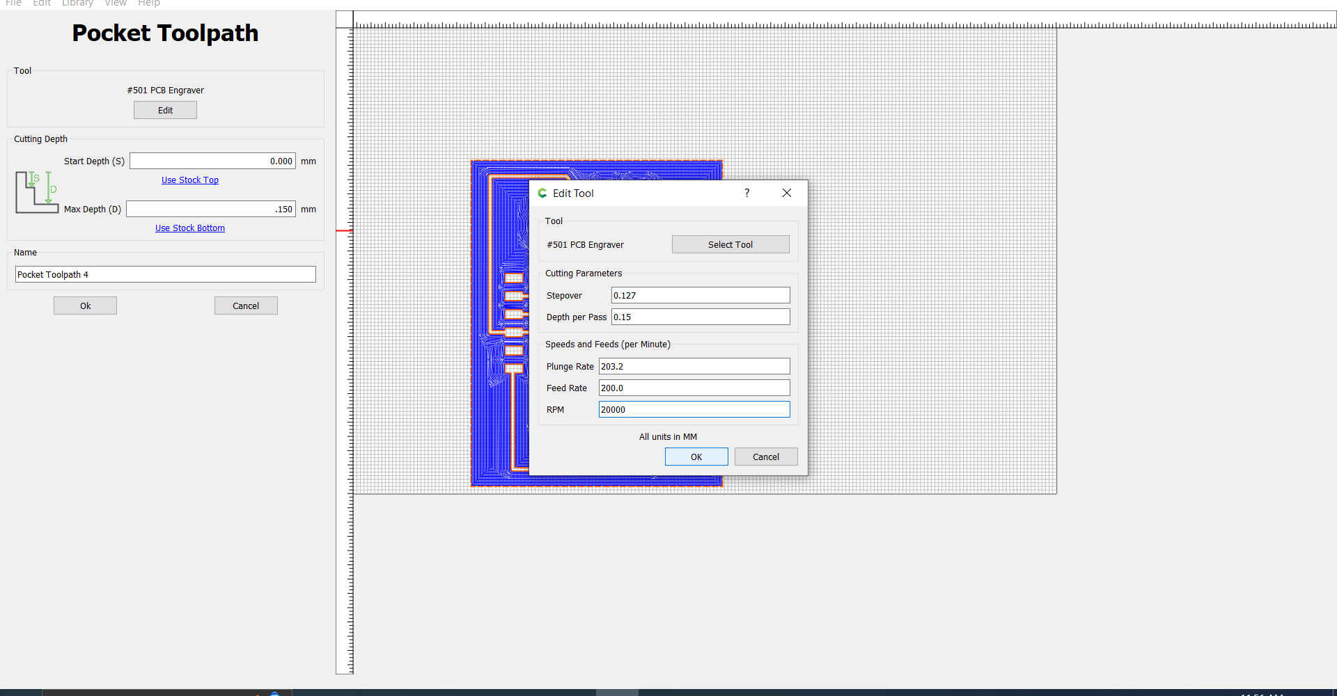
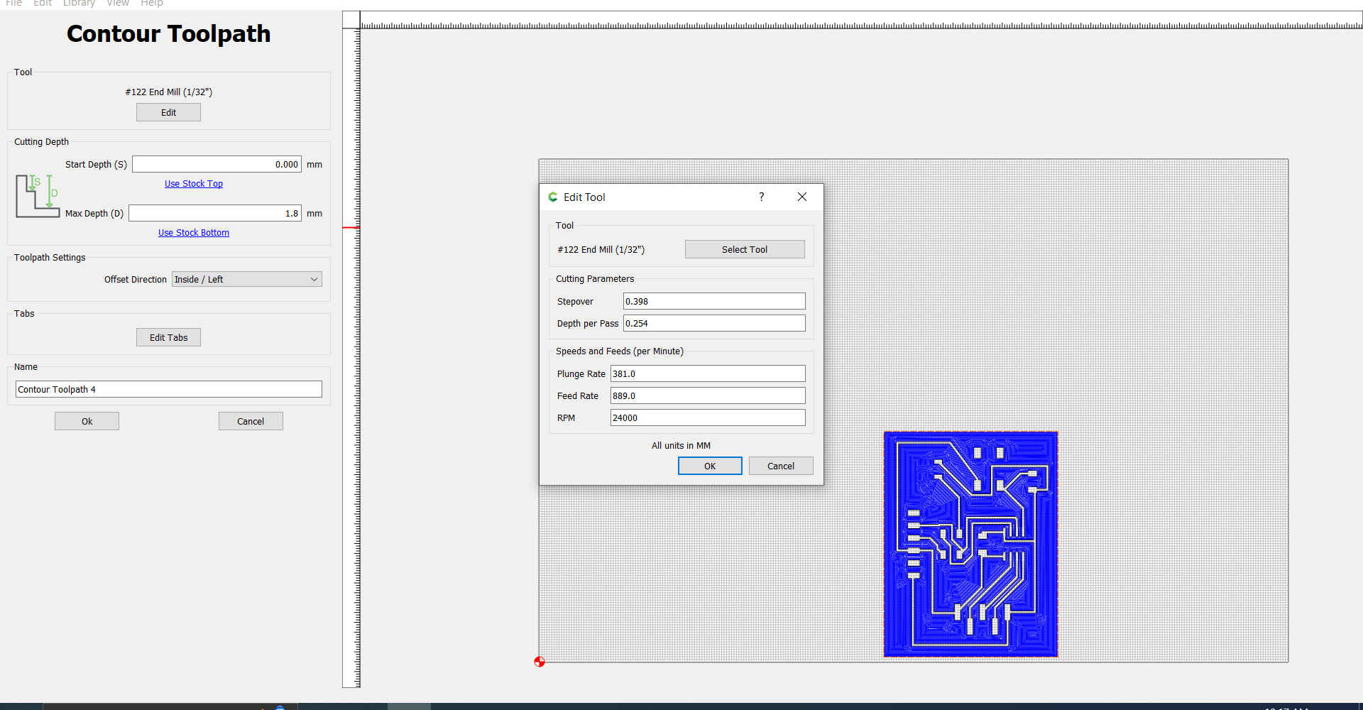
 Note. Record the depth per pass for the selected tool.
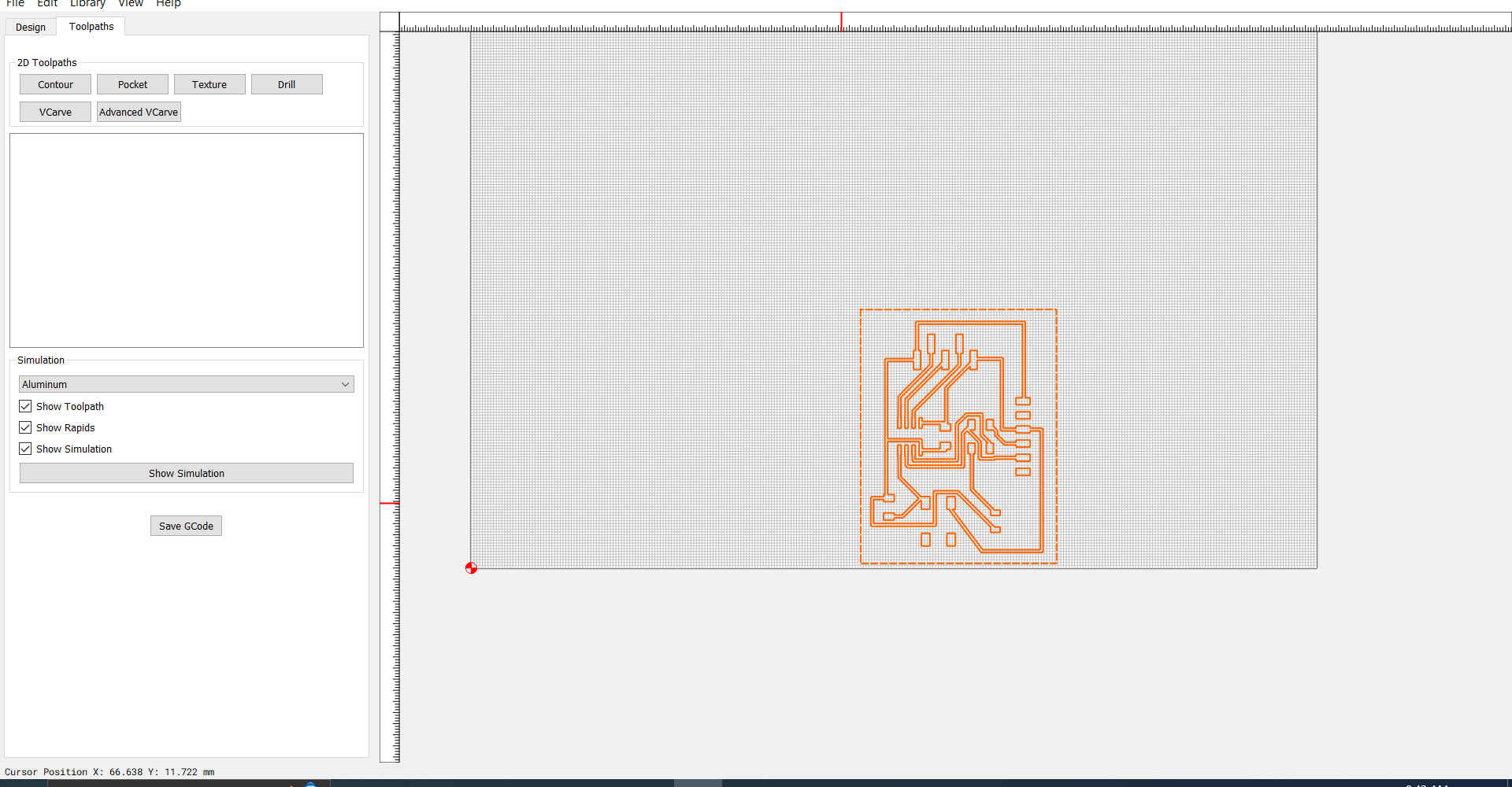
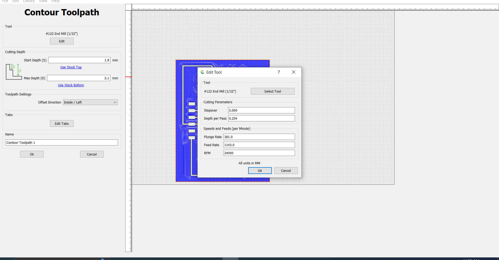
10.Then the outer path was selected and contour chosen as the operation.
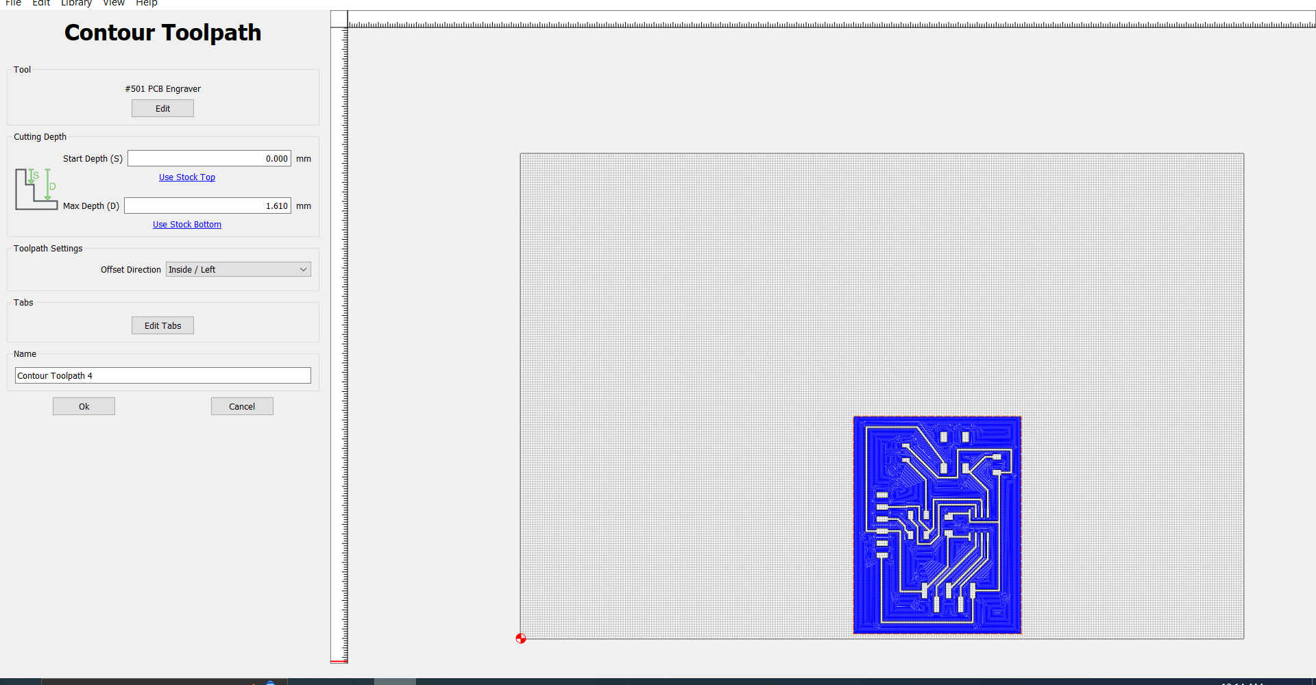
11.At this point, I repeated the process of selecting a different tool that will be used to cut the shape of the PCB.Also making adjustments to the max depth and stepdown as unlike the previous operation this would be cutting the shape out.
12.As both tool paths were created, I then disabled each part individually and saved the gcode to be used by the machine.
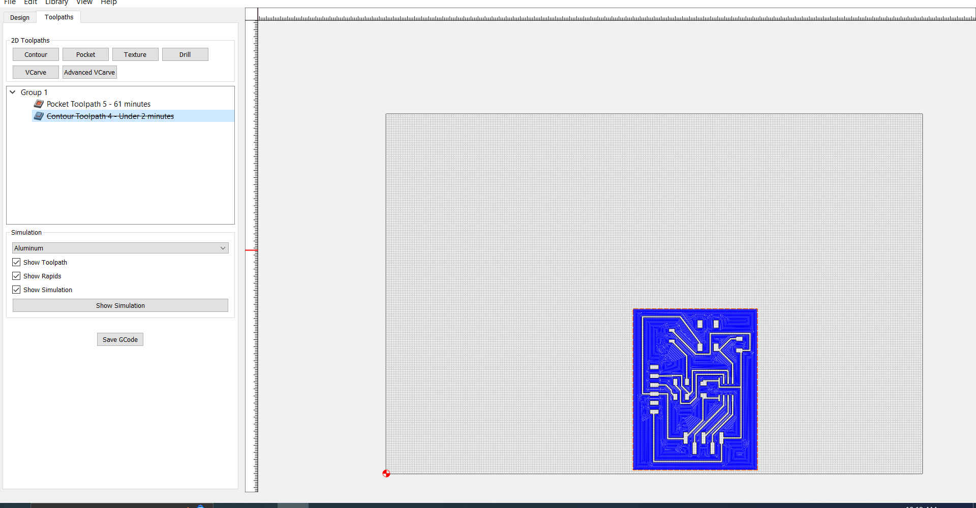
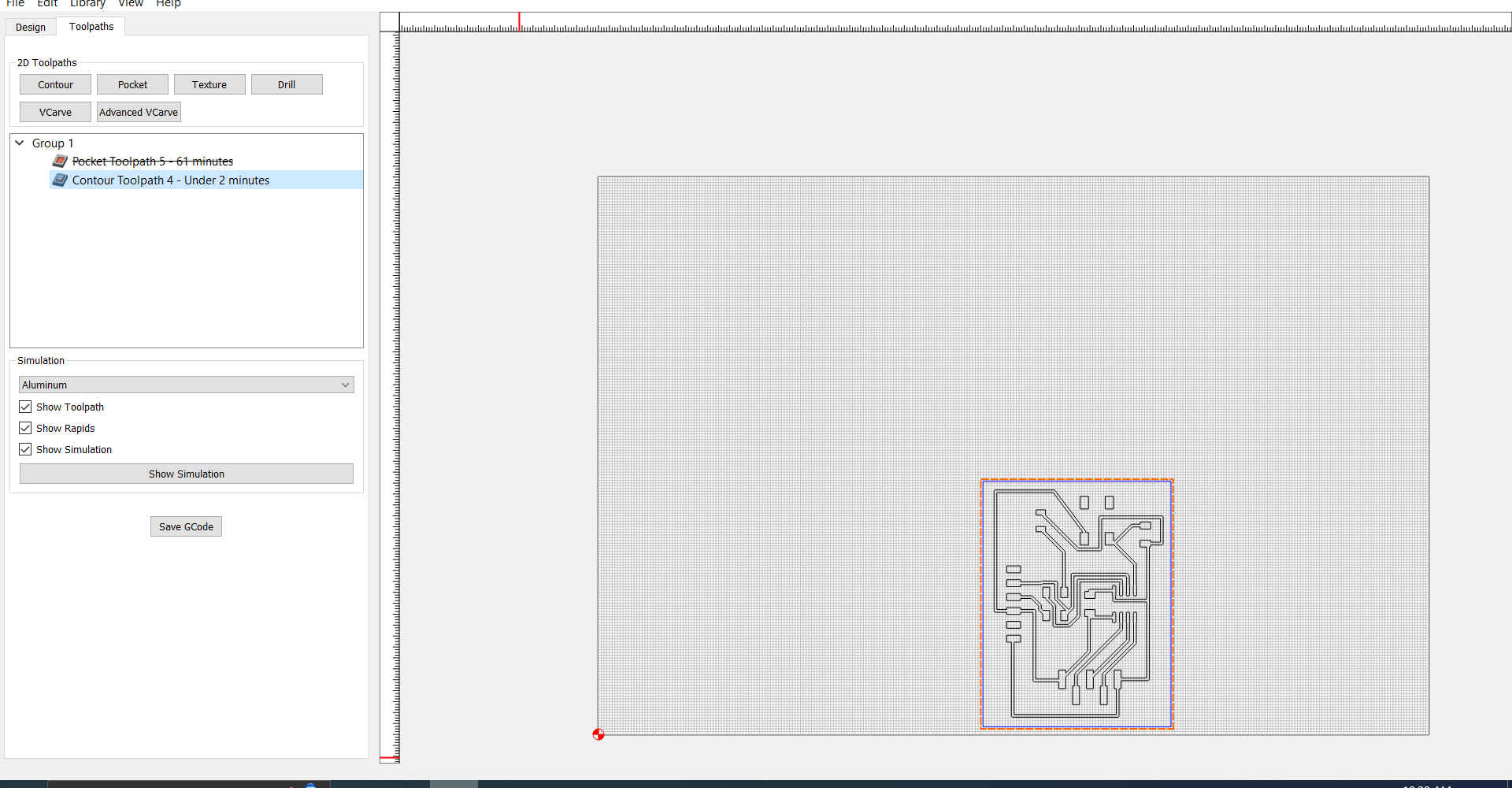
Note. There are different gcode option depending on your machine preference. You can also preview a simulation of the job before creating the final gcode.
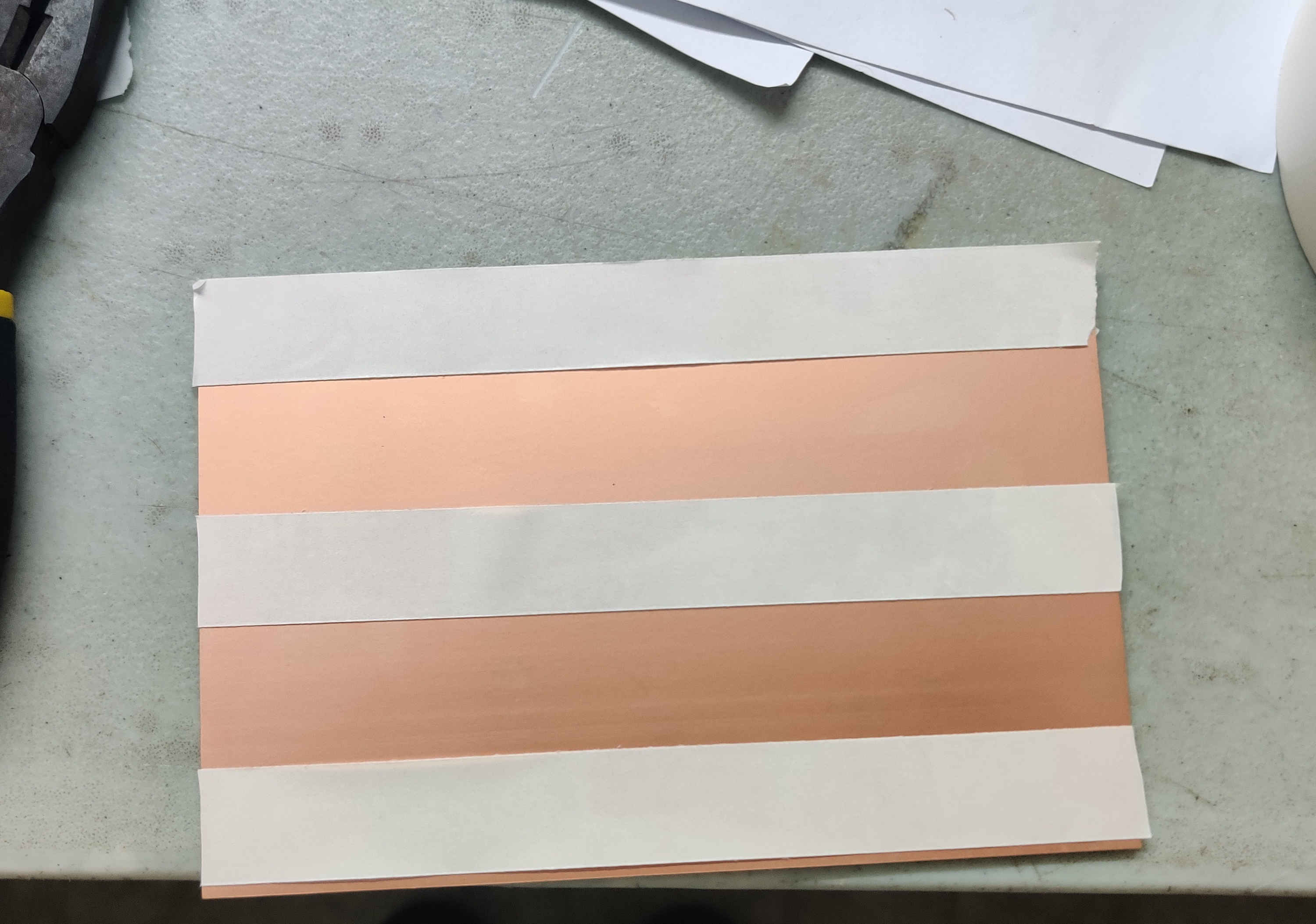
13.Then I prepare the the milling machine to create the board .
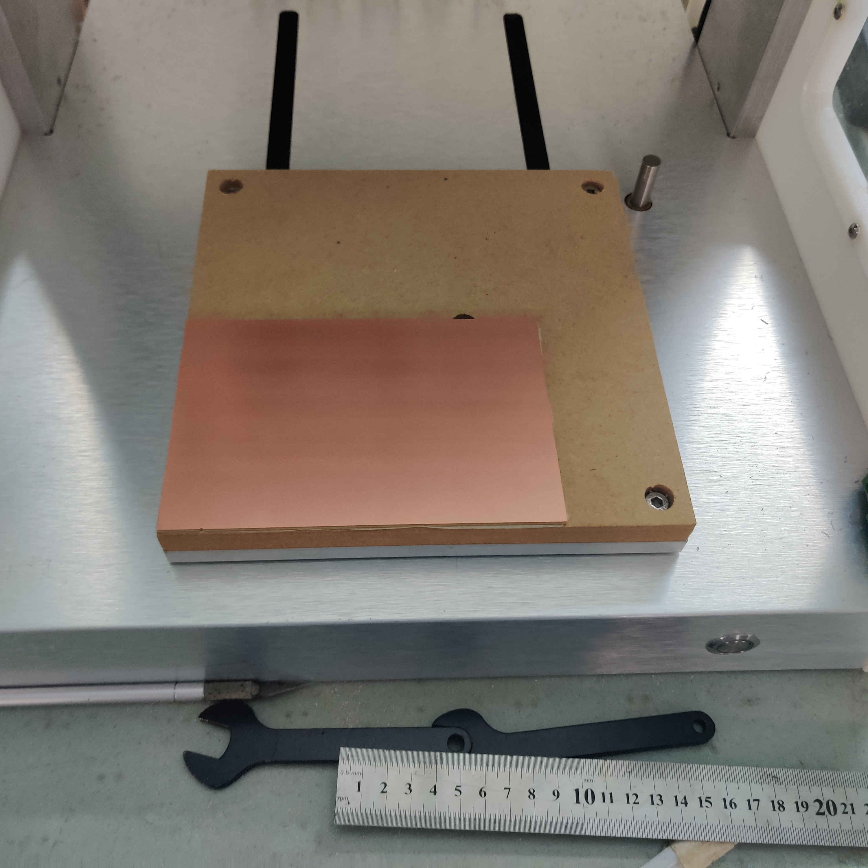

14.Then I opened the gcode in Carbide Motion(software for machine) and milled my board.

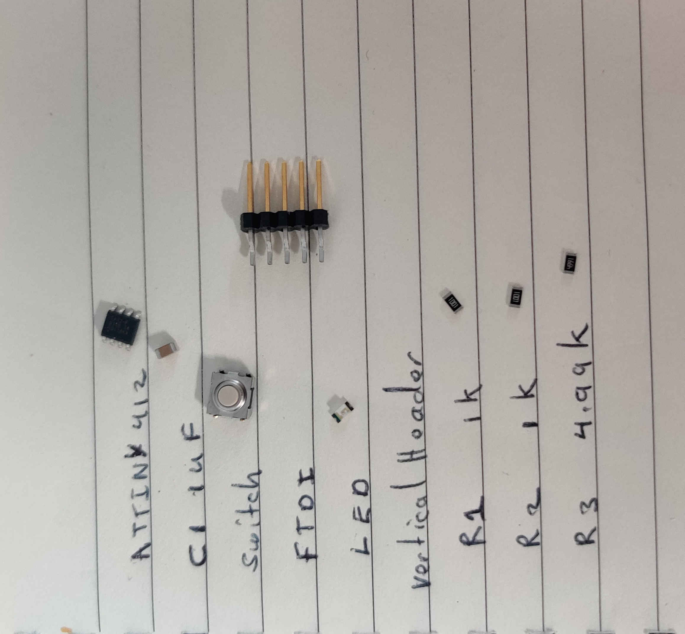
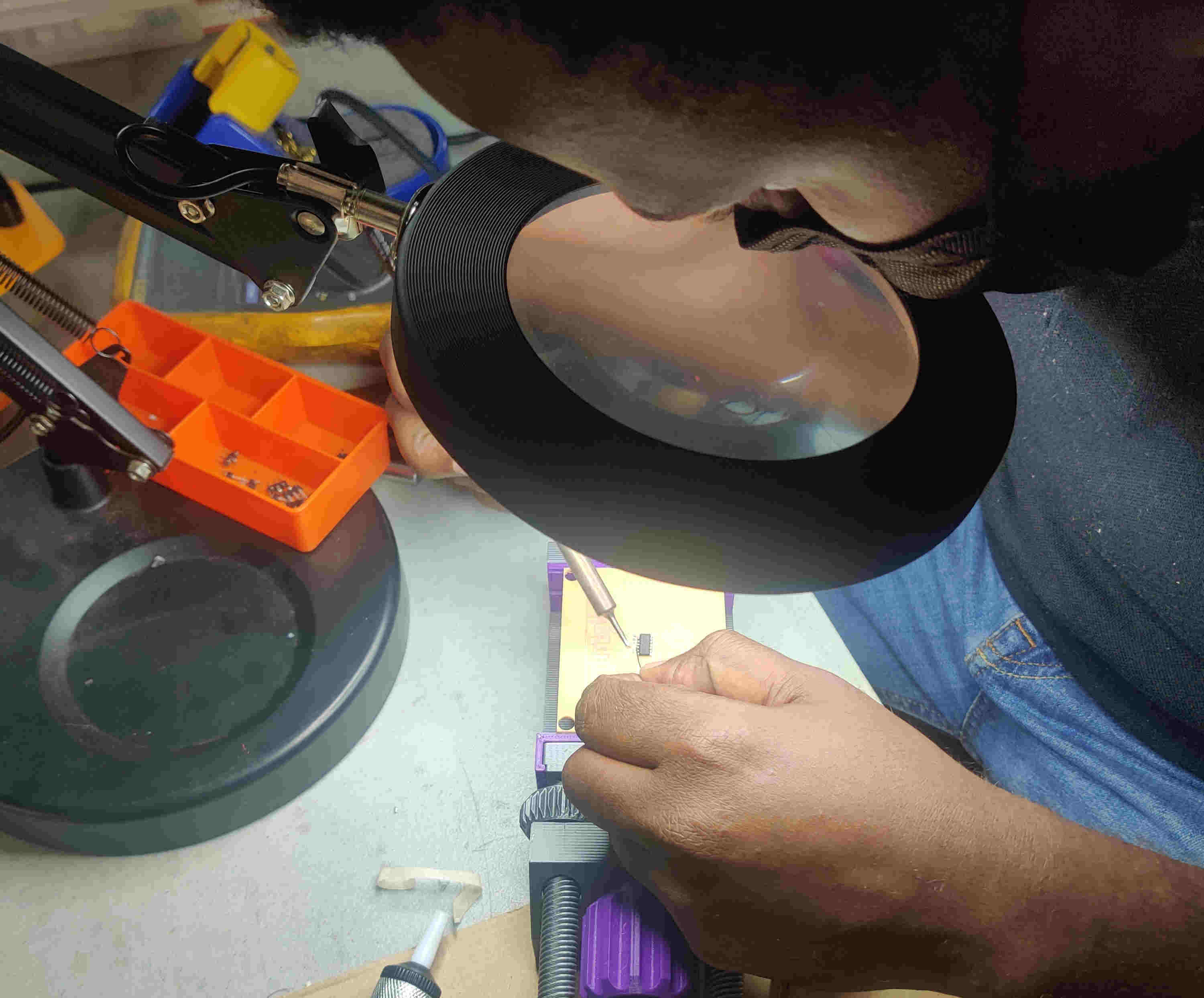
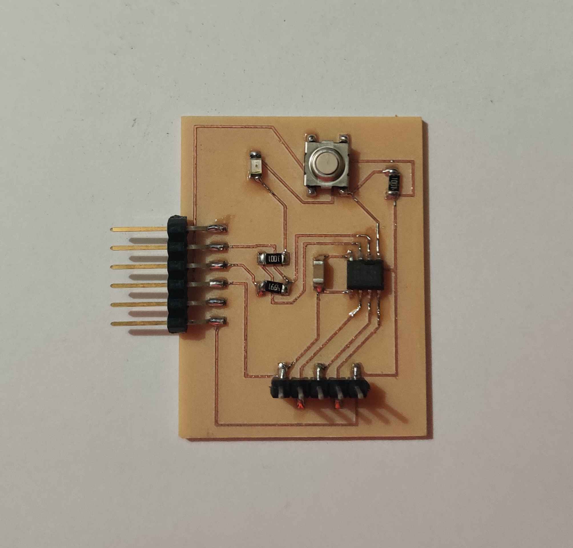
15.Then I gathered all my components and placed them on the board.